Quarter wave (QW) in simple words
Do not be alarmed by the clutter of these words, we will not delve into the theoretical foundations of the quarter-wave resonator or quarter-wave resonator here, as it is usually called. Let's consider this type of design from the user's point of view, because CV has important advantages and few disadvantages.
In short, a quarter wave is a tunnel of a certain length and cross-sectional area; there are no separate concepts of housing and port, as we are used to in a bass reflex. If there is free space, it is very simple to calculate and does not have any special difficulties in manufacturing.
Main advantages of CV:
- reduced degree of group delay, well-developed bass and detail, sometimes exceeding a closed box;
- wide and smooth frequency range - with the right approach, the upper and lower bass can be easily mastered;
- increased level of efficiency, 20–40% more than that of bass reflexes or bandpasses and 150–300% than that of a closed box.
Just a cheater building - that's how it is! There is only one minus, but a significant one - the large volume of the box.
In other words, if you don’t mind space, then the HF will be the best choice for subwoofer design.
Advantages and disadvantages
But there are few negative aspects to it, many do not even notice them:
- The system is cumbersome. Sometimes it takes up the entire trunk.
- Not suitable for use with power greater than twice the subwoofer's rated power.
But the advantages of installing a resonator are significant:
- Low level group delays. Very precise detail and bass processing.
- The reproduced frequencies become smooth and their range expands. If you correctly calculate a quarter-wave resonator, it can easily handle both upper and low bass.
- Efficiency is high.
Acoustic design labyrinth (quarter-wave resonator)
These are strong arguments for installing a quarter-wave resonator. Many car enthusiasts have gotten used to doing the installation themselves. But it is important to correctly analyze the future system and make correct calculations. You can calculate the quarter resonator online. Now there are websites offering convenient payment technology. The program is called Quarter Wave box. This is an easy and fast way to analyze and design CV boxes. Quarter Wave box is a free program.
ChV calculation
The cross-sectional area of the port depends on the size of the speaker.
It is calculated in special programs; for averaged and simplified calculations, the effective diffuser area is taken.
It is important to know that the effective area (Sd) is not calculated by the standard size (10″, 12″, etc.), it is always smaller since the basket and part of the suspension do not participate in the radiation. Manufacturers often indicate this value in the documentation, but you can also calculate Sd
Sd —effective subwoofer area, cm²;
Sd = π(D/2)2
where D is the diameter in centimeters, taken through the center from the middle of the suspension.
For a square subwoofer, calculating the area is even simpler - you need to square the length of one side.
Effective area of subwoofers
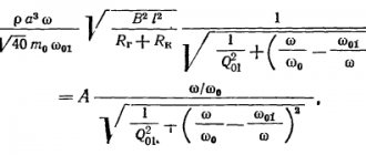
The CV setting depends on the length of the port and is calculated as follows:
— port length, m.
Where:
Fb – desired tuning frequency, Hz
The optimal range is 35–45 Hz, no one forbids setting it low, if you like infra, lower the setting.
Calculation example
For example, let's calculate the frequency response with a setting of 38 Hz for a 12-inch (30 cm) speaker.
S port = 1.5 * 480 (from the table for 12″) = 720 cm²
In order for the box to fit into the car, the port is rolled up.
Self-calculation
There is an established formula that is convenient to use. You need to know the following indicators:
- Tunnel cross-sectional area (S).
- Subwoofer caliber (R).
- Diffuser area (Sd). Distance from the center point of the diffuser to the center point of the suspension. Can be measured with a simple ruler.
Having this data, the formula is applied: S=1.5*3.14*((R^2)).
Quarter-wave resonator
The resonator tuning is determined by the length of the tunnel. Online calculations are easier: here you just need to insert all the parameters into the electronic formula. The system will automatically calculate the result.
Types of CV
Above we analyzed the calculation for a quarter-wave of constant cross-section, but there are also tapering and expanding tunnels.
If sound quality comes first for you, then make a HF with a tapering design. It is larger and more complex to manufacture, but the result is a bass that is accurate, fast and deep. This case is suitable for systems focused on sound quality! Unlike the classic direct HF port, the port is made to gradually taper from 3 Sd to 1.5 Sd at the outlet.
The expanding port will give the highest efficiency and loudness due to the humpback frequency response.
A tapering port will be shorter than the opening for the same setting. See the table for calculated data:
Port length depending on the type of CV
CV for the room
The quarter room resonator is built differently from a regular FI. You can also calculate and install it yourself. In addition to proper calculation, the location of the speakers in the room matters here.
Scheme of operation of the HF resonator
The first step is to check the phase. This is necessary to ensure that the woofers are correctly connected to the amplifier. That is, plus the speaker to the plus of the amplifier. And vice versa, minus to minus.
Nuances
- It is important to make the turns correctly. These are pads installed in the inner corners of the labyrinth partitions to prevent an increase in the cross-sectional area of the port in places of turns. The distance between the edge of the horizontal partition and the rounding surface should be equal to the width of the tunnel on straight sections. Otherwise, when turning, you will get an hourglass shape, which will cause deviations in the tuning frequency values.
- Due to the structural features of the box, thanks to the large number of partitions, material for a subwoofer up to 12″ can be taken with a thickness of 16 mm.
- There is a type of CV, which is also called Rogozhin’s labyrinth. If you want to delve deeper into the theory and delve into the calculations, then here is a site where the developer’s work itself is presented.
Acoustic design labyrinth (quarter-wave resonator)
Good evening to all forum members! After reading the comments, I immediately remembered the institute and the subject of AFU with antennas, long lines and telegraph equations... I think it is not entirely correct (or rather, not at all correct) to compare the radiation efficiency of linear vibrators of radio frequency systems of various lengths (quarter wave, half wave) with the radiation efficiency of an acoustic labyrinth , because it is not the labyrinth itself that emits (even half-wave or quarter-wave), but its outlet, which, like a light piston diaphragm, generates a spherical sound wave. There is no point in proving that our labyrinth is a long line with distributed parameters. The wave resistance of such a line is equal to the product of air density, the speed of sound and the cross-sectional area of the labyrinth. If the line is homogeneous and loaded with a resistance equal to its characteristic impedance, then the line is considered consistent and only a traveling wave propagates in it. The inhomogeneity of our quarter-wave line in the form of an open port (that is, connection with the environment) generates reflections (resonances), the frequencies of which (fundamental tone and overtones) will correspond to the length of a particular labyrinth. In general, the load of our quarter-wave labyrinth line is complex and contains active and reactive components. Removing all the calculations, we find that with resonance at the fundamental tone, the active component of the input impedance of the quarter-wave labyrinth is frequency-independent and equal to the product of air density by the speed of sound and the cross-sectional area. The reactive part of the input impedance is frequency dependent and “runs” to zero as the wavelength decreases (frequency increases) and as the distance from the port “to the listener” increases. In addition, we remember that a quarter-wave segment of a long line is similar to a parallel circuit in lumped parameters (LC - circuit) and has maximum resistance at the resonant frequency. The source of energy for the resonating CVR is the speaker, which feeds the resonating labyrinth with energy. Therefore, when people write that “the CVR is closed” (obviously at the resonant frequency) and “only the diffuser emits”, this is not so: when tuning a quarter-wave labyrinth to the resonant frequency, the speaker intensively radiates the opening of the labyrinth, and the amplitude of oscillation of the diffuser is minimal and the speaker emits very weakly. But “local resonances” (in my opinion, these are overtones of a pipe open at one end) occur in any pipe, both half-wave and quarter-wave, and they are dealt with by laying the walls of the ZPM labyrinth. In my opinion, making a half-wave crankshaft to shift the phase by 180 degrees is a troublesome task in terms of dimensions, and a half-short CVR in our case is “the one” for fans of the labyrinth. As for the “quarter-wave appendix, leveling the frequency response of the emitter”: this is not an “appendix” and its length is not equal to a quarter of the wavelength. In fact, the engineer Rogozhin in his quarter-wave labyrinth “simply” shifted the woofer relative to the beginning of the labyrinth’s CVR by one third of its length in order to suppress the first (and lowest-frequency) overtone, the frequency of which is 3c/(4L). This is the lowest-frequency overtone (relative to the higher-frequency 5c/(4L), 7c/(4L), 9c/(4L), ...), which is the most difficult to suppress by the ZPM. Higher-frequency overtones begin to more or less effectively dampen the ZMP. The conditions for excitation of our CVR at the fundamental frequency are practically not affected by “such” displacement of the speaker, equal to one twelfth of the wavelength (corresponding to the fundamental frequency of the labyrinth), and for a wave whose length corresponds to the first overtone, the excitation conditions due to reflection from the closed wall of the CVR (phase incursion) there will be others. As a result, at the output of the labyrinth, oscillations with the frequency of the first overtone will be greatly weakened. Good health to everyone from Rasponi!
CV for exhaust system
A quarter-wave resonator for the exhaust system is capable of dampening low-frequency sounds that are generated due to engine operation. It is installed for this purpose.
Before assembling such a resonator yourself, you need to understand a few rules:
- The material of the exhaust system directly affects the result of noise reduction. That is, the thicker the material, the more effective.
- The design of the resonator must be thought out and calculated in advance.
- Replacing the air intake box affects the ratio of intake air and exhaust gases.
CV box
Therefore, concomitant adjustments of filtration and air supply should be carried out.
