According to the technical characteristics, the lm7812 microcircuit is a linear stabilizer of positive polarity with a simple switching circuit. Its body has only three external terminals, so many people confuse it with a regular transistor, but in fact it is a more complex semiconductor device.
Belongs to the 78xx series of integrated circuits, widely known throughout the world. The symbols "lm" at the beginning of the marking currently indicate its main manufacturer - Texas Instruments. The first two digits “78” indicate positive polarity, and the following “12” indicate the supported stabilization voltage - 12V.
Tsokolevka
The LM7812 pinout is as follows. This stabilizer is produced mainly in a plastic housing TO-220. The metal terminals, when looking from left to right, have a purpose: input, ground, output. It is very rare, but identical products are found in TO-263 packaging.
It is worth considering that the metal substrate of all the cases considered is physically connected to the “Ground” pin.
see also
Comments 13
The scheme still works right?! Are the diodes also alive? )))
Will the stabilizer not get very hot during operation? It is advisable to install some kind of small radiator from the computer (south bridge or whatever the lower bridge is)
Will not protect against splashes. I don't see any diodes.
If you simply put the stabilizer in the gap to the reversing light without the conduits, will it not perform its function?
Read the comments to this post www.drive2.ru/b/339900/ Everything is written there.
When I overexposed the tidy, I also read this article and made the same voltage stabilizers. and then I read that current stabilizers are needed. but did not redo it. and so the diodes illuminated for a year and not a single one blinked, I hope they still shine
Fuck knows when the tidy was overexposed without any stabilizers. It still works fine. But you can get into the tidy without any problems and redo the burnt-out diode, but getting into the headlights will be more difficult.
It’s easier to order stubs on LMKs. We have these for 19 UAH in the Middle Kingdom a little cheaper. And there will be happiness))
Yes everything works fine.
The eyes will NOT live happily ever after, everything is fundamentally wrong. LEDs (LED) need a current stabilizer, not a voltage stabilizer; if it is not there, the simplest one is a resistor; there is a small black dot on the tape. For normal operation of the stabilizer, the voltage drop (input-output) must be at least 2V, preferably 4-5V. In this case, there is a diode at the input, the voltage drop of which is at least 0.5V, maximum 0.8-0.9V. Those. Even when running, work is questionable, and even more so under load. At a minimum, remove this diode. Read about the correct connection of ICE here - www.drive2.ru/l/3638069/
The eyes will NOT live happily ever after, everything is fundamentally wrong. LEDs (LED) need a current stabilizer, not a voltage stabilizer; if it is not there, the simplest one is a resistor; there is a small black dot on the tape. For normal operation of the stabilizer, the voltage drop (input-output) must be at least 2V, preferably 4-5V. In this case, there is a diode at the input, the voltage drop of which is at least 0.5V, maximum 0.8-0.9V. Those. Even when running, work is questionable, and even more so under load. At a minimum, remove this diode. Read about the correct connection of ICE here - www.drive2.ru/l/3638069/
I read the post. I do not understand. Why won't everything work properly for me? I installed the tape already with a resistor (there is a small dot on the strip). This means that the current under the diodes is already stabilized. And for proper operation of the diode strip you need 12 volts. This is how my voltage stabilizer copes properly. It eats up its 2 volts and produces 12 volts. You can see it from the photo. So why won't the eyes live happily ever after? Thanks in advance for your answer.
At full load, the mains voltage is less than 14V. And when it’s not full, it’s about 14.3 maximum. All this is on the verge of the stabilizer working. But the diode drops (I already wrote), nowhere in the manuals have I seen a circuit with the inclusion of such a diode, so remove it. With him the line is narrower. Such a stabilizer must be powered with at least 16V for normal operation. On the other hand, if it says 12V on the tape, it does not mean 12.0V, period. Therefore, 14V will be normal.
Specifications
7812 is also called a regulator with a fixed voltage of 12 V. In this case, the input of the microcircuit must be supplied with power 2-3 V more than the output, otherwise it will not have the declared 12 V. The maximum output current can reach 1.5 A using good radiator. The device is technologically protected from thermal breakdown, short circuit and exceeding safe operating conditions (SOA). Which makes him practically “unkillable”.
Maximum parameters
The maximum performance values for the LM7812 are:
- maximum voltage at the input of the microcircuit is no more than 35 V;
- output current up to 1.5 A;
- The temperature of the crystal during operation can reach +150 °C;
- storage temperature from -65 to +150 °C;
- permissible solder heating is no more than +230°C, with intervals of up to 10 seconds.
Power dissipation is limited by internal protection (Internally limited), the housing design of the product and the use of a heat sink.
When calculating the maximum power dissipation of an operating device, the standard formula PDmax = (TJmax - TA) / θJA is used. Where TJmax is the maximum temperature of the crystal, and TA is the expected temperature for the surrounding air. θJA is the thermal resistance to the external environment, which directly depends on the housing design.
For example, for common devices in plastic TO-220 θJA=54OC/W. In the case of using a radiator, it is necessary to take into account the thermal resistance of the crystal (θJC), which is about 4°C/W for such a case.
Electrical parameters
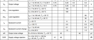
Despite the fact that the power dissipation is not listed by the manufacturers in the datasheet along with the maximum parameters, its recommended value can be seen in the electrical characteristics of the LM7812. The “testing conditions” column indicates the permissible PD value of no more than 15 W, when the input voltage changes to 27 V and the output current to 1 A. The crystal temperature, in this case, should be in the range from 0 to +125 °C.
The data presented in this table was obtained by testing with two smoothing capacitors at the input (up to 0.22 µF) and output (up to 0.1 µF).
Stabilizer L7812CV
Selection of 12 V stabilizer
The car's on-board network provides power from 13 V, but LEDs need only 12 V to operate. That is why it is necessary to install a voltage stabilizer, which will provide exactly 12 V at the output.
By installing such equipment, it will ensure normal conditions for the operation of LED lighting, which will not fail for a long time. When choosing stabilizers, motorists are faced with problems, since there are so many designs, and they all work differently.
You should select a stabilizer that:
- It will function correctly.
- Provides reliable protection and safety of lighting equipment.
lm7812 stabilizer 12 V
The 7812 voltage stabilizer changes the voltage up to 20 V to 12 V. This device was often used to create a stable operating voltage for low voltage devices: audio amplifiers, microcontrollers, lighting lamps.
An unstable voltage value, and even a variable value, can be connected to the input stage. LM 7812 is a stabilizer included in the 78xx series of microcircuits. They differ only in the output voltage, other parameters remain the same.
For better heat dissipation, a cooling radiator is attached to the stabilizer body. It can be removed from old devices from the board. Instead of a radiator, you can use tin from cans, cutting it into strips and drilling holes in them for mounting with a screw.
A simple 12 V voltage stabilizer with your own hands
If you have even minor skills in assembling an electrical circuit, then it is not necessary to purchase a voltage stabilizer ready-made. To make a homemade device, a person will spend 50 rubles or less; a ready-made model costs slightly more. There is no point in overpaying, since the result will be a high-quality device that meets all the necessary requirements.
The simplest but most functional stabilizer can be made with your own hands without much effort. It is very difficult to assemble a pulse device, especially for a beginner, and therefore it is worth considering linear stabilizers and amateur circuits for it.
The simplest 12 volt voltage stabilizer is assembled from a (finished) circuit, as well as a resistance resistor. It is advisable to use the LM317 chip. All parts will be attached to a perforated panel or universal printed circuit board. If you assemble the device correctly and connect it to your car, you can provide good lighting - the lights will stop blinking.
Read also: Terminal blocks for twisted pair
Diagram LM317 Connection diagram
Three-terminal stabilizers
For many non-critical applications, a conventional 3-pin regulator will be the optimal choice. It has only 3 external outputs. It is factory set to a fixed voltage. The 7800 series are representatives of stabilizers of this type. The last two digits indicate the voltage. We have already talked about one of this series earlier (7805)
Connection diagram
The LM7812 itself is a voltage stabilization circuit and the device is usually connected to it only for this purpose. In fact, nothing else is required to perform this function. Beginning radio amateurs use it in their developments without additional strapping and it works for them, but this is not entirely the right solution.
It is advisable to follow the manufacturers' recommendations, which provide a 7812 switching circuit using two capacitors of 25 V or more. They must be soldered as close to the contacts as possible for more stable operation of the microcircuit. In this case, more capacitance is required at the input than at the output. Failure to comply with this rule leads to instability of the output voltage when there is a sudden change in the load. In addition, such capacitive piping performs protective functions against self-excitation.
The passport states that it is permissible not to install a smoothing capacitor at the output at all. This is possible due to the fact that the role of the power control element inside the 78xx series is performed by an emitter follower based on a Darlington transistor. But as practice shows, a small capacitance is still installed for better suppression of output high-frequency ripples.
An example of how such a scheme works can be seen in a short video.
L7812
L7812 (7812). ,. ,
L7812
. L7812 L7912 ,.
, 1.5,,. , technical specification P-N-P. with N-P-N, 803/805/808,. P-N-P, 70-80-,. D1 0.6 Q1,. D1 1N4007. 1st quarter 803, 805, 808, 819. ,: 3 -,,. « R1 0.6 Q2 Q1. Q1. ,
? :
P = (UU) * I
102.2) /R1=1.8, 50% 4.
:
: L7812: ,,. ,: sheriff,
% PDF-1.3 % 103 0 object > endobj Xref 103 40 0000000016 00000 n. 0000001151 00000 n. 0000001680 00000 n. 0000001897 00000 n. 0000002177 00000 n. 0000002567 00000 n. 0000002717 00000 n. 0000002758 00000 n. 0000003562 00000 n. 0000004079 00000 n. 0000004780 00000 n. 0000004804 00000 n. 0000021995 00000 p. 0000022019 00000 p. 0000039731 00000 p. 0000039755 00000 p. 0000056853 00000 p. 0000056877 00000 p. 000007423 1 00000 p. 0000074255 00000 p. 0000091437 00000 p. 0000091461 00000 p. 0000109367 00000 p. 0000109391 00000 p. 0000127233 00000 n. 0000127257 00000 n. 0000144391 00000 n. 0000147506 00000 n. 0000153529 00000 n. 0000153734 00000 n. 0000153873 00000 n. 0000154010 00000 n. 0000154150 00000 n. 0000154367 00000 n. 0000475710 00000 n. 0000475907 00000 n. 0000476087 00000 n. 0000476284 00000 n. 0000001240 00000 n. 0000001658 00000 n. trailer ] >> startxref 0 %% EOF 104 0 object > endobj 141 0 object > flow Hb«`l @ ( 0! G L2LB [JzTge7vdsqԆg @ OOM.P7 (lQI & ѥvl & Birn $ g \> & Km [lV. G rrHT1 Mj8oi V0% QajX $ 7 $ BӀBNb0D50
w4Q
.

