Hello dear readers of our favorite portal Datagor.ru!
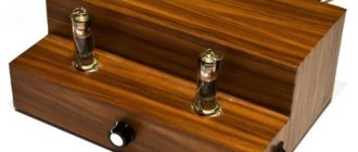
I haven't been heard from for about a year. During this time, I managed to become a father and the time for amateur radio suddenly became less. But I did not abandon my radio-electronic research, but brought to life one of my most ambitious projects in the field of ULF. There was a lot of time for thinking and little time for practical implementation. The project was carried out slowly, so the quality of the details was as high as possible. I didn’t spare money to achieve the result I needed and didn’t make compromises to reduce the cost or simplify the design.
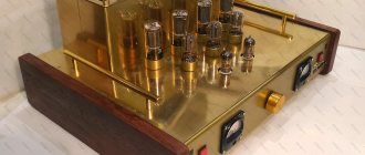
"BRASS"
- because everything lives in a body made of polished brass 1.5 mm thick and varnished. For other funny translation meanings, see the English dictionary.
The project includes:
— The main stereo ULF block according to the Nobu Shishido circuit with a push-pull output to 6P3S. — Tube RIAA stereo vinyl corrector for 6N2P. — MP3 unit operating via USB with flash memory. — Remote control of the MP3 unit. — Remote control of the main amplifier volume potentiometer using a brush motor.
In the first part of a series of articles, I will talk about assembling the main amplifier and corrector circuit for connecting a vinyl player.
↑ Selecting an ultrasonic frequency circuit
Choosing the circuit for the main ULF block was long and painful.
I looked at a lot of diagrams, both on our Datagor and on third-party sites. I even listened to samples of homemade amplifiers on Youtube (which, by the way, predictably turned out to be useless, since the filming does not convey the distinctive features of the circuits in terms of sound). The choice was between a push-pull amplifier based on 6P3S and 6S33S. I have already heard both lamps in push-pull operation. I have a 6P3S guitar combo amplifier and the sound of this lamp is pleasant to me. I heard 6С33С many times from an audiophile friend who wound the output transformers with the overall power of iron slightly lower than the dissipation power of the lamps in push-pull operation, which could not but affect the sound, which, to my ear, seemed somewhat hysterical, thereby distorting my idea of this lamp.
The only option left is the two-stroke 6P3S. Among the articles on Datagor.ru, I liked the implementation of comrade Mikhail (Lektor) with his modification “Push-pull tube amplifier on 6P3S based on Nobu Shishido.” Having studied the original source and its modification, I decided to test everything in practice and choose a sound more favorable to my hearing.
I definitely like the idea of a higher current driver. The sound of the pentode switching seemed unusual to me, because I was used to the triode sound.
Stabilizing the grid at a relatively high voltage using a gas-discharge zener diode SG16P, in my opinion, does not make any changes to the sound - whatever I listened to in this version, from pop to metal.
Feedback - I didn’t even try here, because I am an ardent fighter against feedback in tube amplifiers.
Tube Amplifier Builders (Kit)
Tube amplifier kit (Kit) George Ohm Audio MX-34M
Description:
The push-pull final stage (Push-Pull) is made on the well-known EL-34EH lamps (matched four). Two lamps per channel. It operates in ultra-linear switching, class A, while delivering 25 watts of power per channel. Almost perfect tonal balance and excellent localization of musical images in space. Powerful power supply and the highest energy rating of Hitachi high-speed electrolytic capacitors 3.6 J/W. It even allows you to give a head start to many well-known transistor brands in the field of bass. And the bass is very energetic and every note is easy to read. The biggest advantage is that when playing the most complex compositions in rock music there is no “mess”, and each instrument is clearly distinguishable. Of course, large musical orchestras also sound high quality. The model has been produced for more than 5 years and has proven itself very well.
On the basis of this model, KITs (construction kits) are made for those who like to make an amplifier themselves. With documentation and free technical support by email. mail, skype and telephone. Until full launch.
MX-34M amplifier circuit with power supplyPeculiarities:
- All this quality is facilitated by separate power supplies for both the final stages, and the preliminary stages are also powered separately. Intermodulation distortion is very sharply reduced, which is very noticeable on loud music.
- The MX-34M model uses transformers with a middle partition - with ideal symmetry of the arms, on magnetic cores ШЛ32х32х80х25, each weight is 3.6 kg. (Our development is very successful). Raa=6.5kom/8ohm. Inductance -80H. It is simply “out of competition” in such price categories.
- At the amplifier input there is a 3-position input switch (6 RCA sockets), a paired ALPS 2x50k volume control.
Brief characteristics:
- three-tube buildup
- switching on the EL-34EH end lamps with the ultra-linear,
- output transformers are perfectly symmetrical across the shoulders.
- Case dimensions: width-430mm, depth-390mm (with fittings), height-170mm. Weight-19kg.
- Sensitivity -0.6 V / 50 kom (ALPS 2x50 k)
- Output power at 8 and 4 ohms 25 watts. (at Ua=355v) per channel
- Tubes in the build-up are 6N6P (at the input) and 6N2P-EV-phase inversion stage. Output tubes, matched four EL-34EH
- The operating frequency range of the circuit (at a power of 25W) is 12Hz -70,000Hz. (by -3dB) (The output range is much wider, up to 110,000Hz)
- Consumption from the network -200W (power supply -300W)
- Noise level – 700 µV/15V - at -90 dB.
- Coef. nonlinear distortion less than -0.5% at 20 watts.
- Separate power supplies for anode and power supply.
- With tetrode switching, the output power is more than 30 watts. to the channel.
- Interstage capacitors K40U-9.
- The power supply uses high-speed electric current. Capacitors 680M 400V -4 pcs. 220M 400V -4 pcs. and 82m 400v-2pcs.
Reviews and additional information: www.audioportal.su
Price: 1170$
Tube amplifier kit (Kit) George Ohm Audio MX-88
Description:
The push-pull final stage is made using the well-known KT-88EH lamps (matched four). Two lamps per channel. It operates in ultra-linear switching, class A, while delivering 30 watts of power. to the channel. Almost perfect tonal balance and excellent localization of musical images in space. Powerful power supply and the highest energy rating of Hitachi high-speed electrolytic capacitors 3.6 J/W. It even allows you to give a head start to many well-known transistor brands in the field of bass. And the bass is very energetic and every note is easy to read. The biggest advantage is that when playing the most complex compositions in rock music there is no “mess”, and each instrument is clearly distinguishable. Of course, large musical orchestras also sound high quality. The model has been produced for more than 5 years and has proven itself very well.
On the basis of this model, KITs (construction kits) are made for those who like to make an amplifier themselves. With the necessary documentation and free technical support by email. mail, skype and telephone. Until full launch.
MX-88 amplifier circuit
Peculiarities:
R33 – overall 6dB OOS, connected to an 8-ohm winding. R33 - Shallow negative feedback of exactly 6dB is connected to the 8 ohm winding of the output transformer. You can do without it, the sensitivity will become 0.32V and the overall noise will increase slightly, but quite insignificantly, but the stage will expand even more and “lamp warmth” will be added. But this is not for everyone. The depth and width of the stage is sufficient and with this inclusion there are 3 main inclusions in this option:
- Triode (screen grids are connected to the anodes through their 100 ohms, while the output power is 16-18 W
- Ultralinear (optimal) -30W per channel
- Tetrode screen grids are connected to common + out. Tr-ra through its 100 ohm - 40 watts per channel - it simply “blows the roof off” - this is for avid rockers.
In each option, with or without OOS, or change the depth (it’s easier to connect either to the 8 or 4 ohm winding of the output transformer). But the most recommended is the ultralinear option. It has all the advantages of p1. and p3. You can listen without general OOS.
Characteristics:
- Turning on the lamps with the ultra ruler
- Sensitivity -0.64 V/50KOM
- Output power at 8 and 4 ohms 30 W (at Ua=355v)
- Tubes in the build-up 6N6P (driver) and 12AX7 phase-inverted stage
- The operating frequency range of the circuit is 14Hz -70,000Hz (in OdB)
- Exit tr-r at 1W 4Hz-90kHz and 100kHz at -3dB
- Noise level – 700 µV/15V - at -90 dB
- Coef. nonlinear distortion, less than 0.5% at 20W
- Separate power supplies for anode and power supply
- When switched tetrodely, the output power is 40 W per channel.
Reviews and additional information: www.audioportal.su
Price: 1330$
↑ Scheme from my project
As a result, I assembled a hybrid circuit with a higher current driver relative to the original and the original terminal, but without feedback.
In the diagram you can see the vinyl corrector block, which I will talk about a little later.
The high-resolution diagram is in the archive below. Resistors from 0.5 to 2 Watt MF 5%, 5 Watt Chinese ceramic. I would like to note that in my version of the driver, anode resistors (R30 in the diagram) should be used with a power of 5 Watts (2 Watt resistors will turn black). I used film capacitors for all interstage capacitors for a voltage of 400 Volts.
↑ Description of catering
I’ll start the description of the circuit with the main one – the power supply, or rather three power supplies.
The main problem was to find a network transformer with a load capacity of at least 0.38 A at a voltage of 300-350 V on the secondary windings.
The solution was to purchase three TAN-55 transformers from the local radio market and connect the secondary windings in series.
Conclusions TAN-55
The photo also shows a 220/12V step-down transformer with a load capacity of 1A, which was introduced into the design later, during the development of control and lighting.
I used a two-level filter rectifier.
At the first stage, a field-effect transistor filter, or an electronic choke (whichever is more convenient) proposed by Loki and TANk, and at the second stage a regular P-filter (capacitance + choke + capacitance). I didn’t skimp on copper, so I used a pair of D47 chokes.
There is a divider at the output to remove the voltage of about 40-60V and apply it to the middle filament point to close the parasitic filament-grid diode of the lamp.
The power supply is made on a separate board as a monoblock with two-stage filter elements and a 6P3S lamp bias rectifier.
I used UF5408 ultrafast diodes for the anode supply, and BYV26C schottky diodes for the bias. For ease of adjustment, I installed trimming resistors at the top edge of the board. Each amplification channel has its own power board.
Hedgehog-type transistor IRF740 radiator 54x32x25mm. When testing the maximum power of the amplifier, it heated up to 37-39 degrees.
Input electrolytic tanks must be 450V. If you use it at 400 V and run it without load, it will definitely be “rose”. I took film capacitors with a reserve of 630 V.
To power the vinyl corrector
used one common stage with a field-effect transistor filter and a parallel P-filter circuit.
The current consumption of the anode of the 6N2P lamp is less than 10 mA, so I decided not to make a separate field-effect transistor filter for each channel.
The filament of the vinyl corrector lamps is powered by direct current using the same P-filter, which was not my maximalist whim, but a necessity.
The background in the incandescent circuit was overcome only by introducing a choke (which I wound with my own 0.35 wire on the iron from the D232 inductor) into the circuit. Vinyl corrector power supply
made on a separate board.
I decided to combine the filament rectifier on the board with a remote control circuit and the second arm of the high voltage P-filter.
↑ Settings for the balance of the arms and anode current of the output stages
As I already said, the amplifier is assembled according to the Nobu Shishido circuit, which many have seen and perhaps heard more than once. I want to dwell on the settings for the balance of the arms and the anode current of the output stages.
Due to the fact that the phase inverter arms are unbalanced, load resistors R34 and R35 have different values - 24K and 27K, respectively.
To establish symmetry, you need to apply a signal to the amplifier input (in my case it is 1 kHz from the generator) and use a 1 µF 400 V film capacitance to measure the voltage level on resistor R35 with a tester, then discharge the capacitor and perform the measurement on R34.
Then take additional resistors from 100 Ohms to 3 kOhms and connect them in series with resistor R34, each time measuring the voltage values, first discharging the capacitor. On my board, resistor R34 is composite for ease of setup.
Next, you need to set the anode currents of each 6P3S lamp; for this, by adjusting the voltage with construction resistors on the power boards, we achieve a voltage drop across the cathode resistors of +0.05V.
Tube amplifier. Refinement of the finished board and modification of the circuit.
Hello, dear ones! Below is a short story with pictures of how I made an amplifier using a more “classical” circuit using domestic 6N9S and 6P6S tubes from a finished printed circuit board for assembling a push-pull tube amplifier using the Dynaco A-410 circuit. If anyone is interested, please see cat. LOTS OF PICTURES! Traffic! So, I got this board just like that, for free (the link is exactly the same). Having scoured the Internet, I discovered that this circuit and board arouse keen interest and active discussion among many. For example, here is the fee
And the diagram
The scheme raises questions among many. And the manufacturer himself, in his next models, abandoned it. On the farm there were 6P6S lamps and their “military” analogue 1515, output transformers (they were wound for other lamps and had to be slightly adapted to these ones), a power transformer (also slightly “finished”) and other parts.
I assembled it, played a lot with the settings and, not receiving the declared and expected parameters, decided to completely redo everything.
It was decided to implement the amplifier according to a proven and retested circuit.
But how can this circuit be installed on a board “tailored” for another? Looking carefully, the task turned out to be quite simple. It is enough to make 11 breaks in the existing tracks and drill 8 additional holes.
Placement of parts and jumpers in the picture below
The layout showed very good results.
and it was decided to bring the project to its logical conclusion. Result in the photo
In numbers, the parameters are as follows: Absolutely honest and clean 8 W at 8 Ohms with a THD of about 0.8...0.9%. Intermodulation on “standard” frequency pairs from SpectraPlus is about 0.45%. The feedback is very small, just enough to align the channels according to sensitivity, about 1.5...1.8 dB. At 10 W output, the THD is about 3.5% At 10% THD, the output is about 13 W. The background from the network and its harmonics are no higher than -85 dB, i.e., it is absent even when turned all the way.
It sounds clean, legible, intelligible and “velvety”. Both I and the family “audience” liked the sound.
Ask about indicator heads? They are from here. There are similar ones, upside down. https://aliexpress.ru/item/-/4001142663883.html?spm=a2g0s.8937460.0.0.41282e0eEJxHU7&_ga=2.205379472.1630494118.1609262952-985983766.1601124750&_ga c=1.124211704.1608363097.Cj0KCQiAw_H-BRD-ARIsALQE_2OQtqHdkDyXidr8Oq2p0SnMVFg7jra3TL8-TPq4T_gSOOM1sPV3YcgaAvrxEALw_wcB
I will answer your questions with pleasure. Good luck and good luck to everyone! Achievements and impressions! Health and wishes!
↑ Fighting the background
I assumed that there should be no background, because I made the printed circuit board according to all the rules for wiring the ground in tube amplifiers.
But there was a background. Comrades from our forum gave a lot of advice on how to eliminate it, but the result was still the same. The solution was the article “On the installation of signal circuits in a tube amplifier,” which was posted by Igor Kotov several years ago. (I highly recommend reading it and bookmarking it - it will save you a lot of nerve cells). I performed the so-called double shielding of the interconnect cable and the background disappeared. The problem was interference in a fairly reliable (as I myself assumed) cable from the computer to the amplifier.
↑ Vinyl corrector
The amplifier finished, but it seemed to me that this was too little and I looked towards my converted Melodiya-103 vinyl record player.
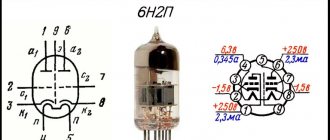
Why not take the signal directly from the pickup rather than stripping it from a brick and mortar preamp? This is how the idea was born to integrate a 6N2P vinyl corrector into the main board. I decided to make the stereo vinyl corrector using 6N2P double triodes, since I had long studied its sound qualities (I didn’t want to experiment). I chose the following scheme
You can adjust the sound of mid and high frequencies using capacitors C20 (from 1n to 470n) and C21 (from 1000 pF to 3400 pF) by adjusting the frequency divider. The output capacitor (necessarily film, audiophile type WIMA MKP10, etc.) has a maximum capacity, but within reason, I soldered 10 μF.
The corrector worked perfectly, but again the background was cut through, which was eliminated by powering the lamps with direct current using a P-filter. The inductor was wound with a 0.35 wire specifically for incandescence on miniature iron from the D232 inductor. It turned out to have an inductance of 0.3H and a resistance of 2 Ohms.
The corrector and amplifier boards are combined, see attached archive.
I would also like to say something about the lamp sockets and their mounting. GZC9-Y-1 sockets were used for finger lamps, and GZC8-1 sockets for octal lamps. They were installed from the side of the tracks, for which all the contacts on the board were mirrored.
Dual triode tube preamplifier
Figure 3 shows a diagram of the preliminary stages of the AEX250 amplifier. They use two ECC808 dual triodes. The tube amplifier has two identical inputs with separate pre-amplifiers on the VL1 tube and level controls RP1 and RP2, after which the signals are mixed and amplified by a common two-stage amplifier on the VL2 tube.
Passive tone controls for low (RP3) and high (RP4) frequencies are installed between its stages. The circuit does not have any other features. For some capacitors, the operating voltage recommended by the manufacturer is indicated. The “AEX650” voice amplifier model, designed to amplify signals from 4 microphones, differs mainly in the construction of preliminary stages.
At the same time, it has separate tone control for low and high frequencies for each input. The amplifier can be connected to the reverb “AKH200” from BEAG, built on the principle of magnetic sound recording on a ring tape. Data on output transformers suitable for the parameters of the output stage of the AEX250 amplifier can be found in the specified literature.
