The article will talk about active filter
for
a two-way amplifier
.
The filter does not require time-consuming setup and is made using available op-amps. The first time I assembled this circuit was about 10 years ago, I needed to boost the Radiotekhnika S90
with a not very powerful homemade amplifier (25-30 Watts offhand), the goal was to find out what these speakers are generally capable of.
But the amplifier power was clearly not enough. And in one interesting book I came across a diagram of this filter. I decided to try to power up the S90 with a two-way amplifier.
One of the advantages is that when the low-frequency channel is overloaded, its distortions are well masked by the mid-high frequency link, therefore the maximum undistorted power to the ear becomes noticeably greater. In the end, I managed to swing one column so much that the slate on the garage began to crack.
↑ Scheme
The second channel is identical, not shown.
For chip power pins, see the datasheet for the used op-amp. The input signal is fed to the non-inverting input of the operational amplifier MC1, which serves as an active low-pass filter with a frequency response slope of 18 dB/octave, and to the non-inverting input of the operational amplifier MC2, which functions as a differential amplifier with a voltage gain Ku=1.
The inverting input MS2 is supplied with a signal from the output of the low-pass filter MS1. In the differential amplifier MC2, its low-frequency part is subtracted from the spectrum of the input signal, and only the high-frequency part of the input signal appears at the output of MC2.
Thus, you only need to provide a given cutoff frequency of the low-pass filter, which will be the crossover frequency.
The values of the filter elements are found from the relations:
C1 = C2 = C3;
R1 = R4; R5 = R1/6.8; R1×C1 = 0.4/Fp, where Fp is the crossover frequency. I took R1 22 kOhm, and then everything is calculated using formulas depending on the required crossover frequency.
Final audio power amplifier circuit
To simplify the circuit and in order to reduce the size of the finished device, TDA series microcircuits were used as final amplifiers, which are widely used in small-sized audio equipment, for example, in car radios. These microcircuits, as a rule, have quite acceptable characteristics for household equipment of quite high quality. Moreover, they have built-in protection circuits against overload, overheating and short circuits in the load. The power characteristics were determined solely by the powers of the available speaker systems. Thus, for the MF-HF band, a TDA1558Q MS was used in a bridge connection. This MS can be connected using a 4-channel 11 W circuit, or a bridge circuit 2x22 W). For speakers with a power of 20 watts, the following bridge circuit was used (Fig. 3)
Circuit 3 – 1558 power amplifier
The scheme is extremely simple and obviously does not require a separate description. Unused MS pins - 4,9,15 - should be left free. If a separate MUTE / ST-BY switch will not be used, pin 14 MC should be connected directly to the positive power supply wire. It is advisable to place a large-capacity electrolytic capacitor (2200 mF) as close as possible to the MS terminals. Not only the quality of smoothing the supply voltage, but also the overload capacity of the amplifier depends on its capacity. A 0.1 mF capacitor is placed in the power circuit to filter out possible high-frequency components. The operating voltage of all elements must not be lower than the supply voltage (+U).
↑ Printed circuit board
As an op amp, I used a quad op amp of type K1401UD2. This board is for him. For a stereo system of two two-way speakers, it is enough to assemble 1 board.
#09/02/2021
Signet From Igor (Datagor) for LM324, LM2902, LM224, LM124:
I combed the PCB, changed the power supply for imported op-amps (!), signed the components according to the diagram, signed the inputs and outputs, etc.
GND - general power supply, ground; +V, −V — power supply ±12V … 15V; IN1, IN2 - audio inputs (LC, PC) from the source (sound card, DAC, pre, phone); HF1, HF2 - HF band outputs for amplifiers; LF1, LF2 - low-frequency band outputs for amplifiers; Power supply capacitors, which are not on the diagram: C50, C53 - 100μF ... 470μF 16V (electrolyte); C51, C52 - 0.1μF ... 0.68μF (film or ceramics); Op-amps - LM324, LM2902, LM224, LM124, etc., quadruple (dip-14 quadruple opamp).
Note:
Imported op-amps and K1401UD2 have inverted power supply! A joke by domestic developers. Choose a PP according to your op-amp.
Pick up the PP in the files.
Crossover filter for two-way speaker system
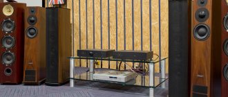
Hello everyone, I continue the series of reviews about homemade acoustics. About the speakers, start here. Today we’ll talk about how not to make a separation filter. What is a separation filter (for fans of Anglicisms “crossover”)? This is a device that allows certain frequency components in a signal to pass through and attenuates others. The filter can be implemented as an analog circuit (passive and active filters), or implemented in software or as a digital device (digital filters). If there is more than one speaker in the speaker system, then in order for the speakers to play consistently across their frequency ranges, a filter is needed that will allow the speaker to play in its own frequency band, in its “comfort zone.” But there is a main feature. A filter for an acoustic system cannot be calculated; too many factors will influence the final frequency response of the acoustics (speaker parameters, their location on the cabinet, bufflestep, etc.) Measurements of specific speakers in a specific cabinet are needed. Of course, this applies to home Hi-Fi, and not low car audio and crafts from domestic speakers in a potato storage box.
Since here is still a site for
for reviews of products ordered in foreign online stores
and not a forum on audio engineering, I will not describe everything in detail, but I highly recommend
that you read this article and this section of the forum.
Now let's look at what the Chinese offer to those who still decide to take the simple path and install a ready-made filter. Since my project is ultra-budget, I chose the very bottom of the market, the cheapest and simplest separation filter for two bands. Filter board sold one at a time.
Board and connection dimensions:
There is a jumper system here:
- Without jumpers - “normal” mode.
- Jumper C1 - high frequency (HF) amplification.
- Jumper C2 - amplification of low frequencies (LF).
- Both jumpers strengthen everything))
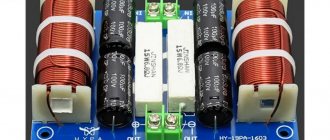
Board appearance:
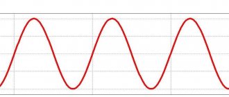
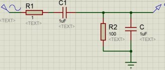
Terminals: amplifier input, woofer output and tweeter output. So, off the top of my head, here is a second-order filter (coil + capacitor) for low frequencies and a first-order filter for high frequencies (capacitor). There is no attenuator made of resistors; if the sensitivity (volume) of your speakers differs, then this is your problem. We expect approximately the following transfer characteristic from such a filter:
But let's take a closer look, turning the board over, the topology falls into place:
This is still a first-order low-pass filter with a subsonic filter. The capacitor here is in series with the coil. One or a pair of capacitors operate at HF. Here, in fact, is the difference between a second-order low-pass filter and a first-order + subsonic:
Subsonic can be useful specifically for small speakers, so that low frequencies do not go to a speaker that is not capable of reproducing them. Let's now look at the values of the elements:
Electrolyte 220 uF 50 V, film 1.5 uF 100 V 2 pcs.
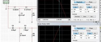
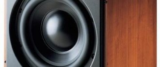
I could not determine the inductance of the coil; it is very small. Here are its parameters: Ferrite frame 6 mm in diameter, 20 mm long, wound with 17 turns of 1 mm wire. Measured performance graphs of this filter:
Two graphs each show the operation of the jumpers. What do we see? Yes, the filter doesn’t filter anything. In terms of low frequencies, the inductance does not work at all (green line), does not drop the frequency response towards the middle (the bass player will play the entire range), the second graph (yellow) is the work of the subsonic speaker. In terms of HF, it is a regular first-order filter. In principle, this entire board can be replaced with one 3.3 uF capacitor.
The result (or rather the lack of result) is quite expected, the low-pass filter does not work, we saved on the coil. But this one will work for my project)) But, if you decide to make a multi-band system, re-
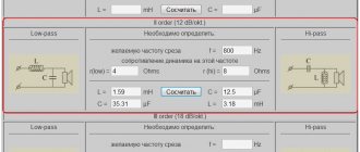
↑ Program for calculating a 2-band AC filter
#08/02/2021
From Igor (Datagor): I made a calculation program in MS Excel for this filter.
We enter the crossover frequency and the value of resistor R1, the remaining values of the circuit are considered automatic. You can move, select denominations closer to existing ones. Range R1 from 10 kOhm to 30 kOhm. You can conveniently print the calculation along with the diagram on one A4 sheet. Help yourself if you have difficulty with manual calculations.