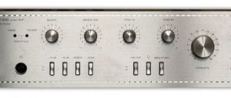
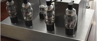
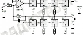
An interesting diagram by S. Filin, I came across it while leafing through old magazines. It is possible to achieve a low level of self-noise with a wide operating frequency band of a low-frequency amplifier if the input stages of both channels of the amplifier are made using vacuum tubes powered by a low anode voltage.
The question of the application, advantages and disadvantages of vacuum tubes, transistors and integrated circuits can be considered finally resolved in favor of transistors and ICs. However, vacuum tubes are still widely used in amateur radio designs, especially in low-frequency amplifiers. Experience shows that to listen to stereo music programs on stereo phones, it is advisable to use a separate high-quality low-power bass amplifier. Realizing high quality performance of stereo low-frequency amplifiers is a very difficult task, and the most important of them - a wide operating frequency band, a low level of self-noise at the output, low nonlinear distortions at maximum output power and large transition attenuation between stereo channels - is very controversial . For example, increasing the output power of a low-frequency amplifier leads to an increase in nonlinear distortion, and the wider the amplifier's bandwidth, the greater the noise level at its output.
↑ Idea
It is possible to achieve a low level of self-noise with a wide operating frequency band of a low-frequency amplifier if the input stages of both channels of the amplifier are made using vacuum tubes powered by a low anode voltage. In this case, the coefficient of nonlinear distortion in the entire range of operating frequencies is minimal and, as a rule, does not exceed 0.2%. The use of an electronic tube at the input also ensures a high input impedance of the amplifier, which allows you to directly connect a piezoceramic pickup to it (for example, N-EPU-32S, I-EPU-52S, I-EPU-62SP, etc.).
Tube-transistor bass amplifier for stereo phones, the circuit diagram of which is shown in Fig.
1, is intended for listening to various music and speech programs when working together with a tape recorder (tape recorder), radio receiver or stereo electronic control unit. The rated output power of each amplifier channel is 0.025 W, sensitivity is about 400 mV, operating frequency band is 20-60,000 Hz with frequency response unevenness no more than ±1.5 dB, nonlinear distortion coefficient is less than 0.2%. The self-noise level with the input open is no more than -75 dB. The amplifier is made in the form of two identical two-stage amplification channels. Input stages based on VI lamp triodes provide signal amplification of approximately four times. The anode load of the left stage is resistor R5, the right one is resistor R7. Trimmer resistor R6 equalizes the gain factors of the cascades. The cathode circuits of the lamp include resistors R4 and R8, which provide negative feedback and low nonlinear distortion of the amplifier as a whole. The lamp filament is powered by a direct current voltage of 6.3 V. The second transistor stage of each amplifier channel is an emitter follower. Galvanic coupling between the stages ensures high stability of the phase characteristics of the amplifier. Capacitors C4 and C5 are separation capacitors between the amplifier and stereo phones B2.
The volume level in the amplifier channels is controlled by variable resistors R1 and R2. The amplifier is powered (except for the filament circuit of lamp VI) from a 25 V DC source. The current consumption does not exceed 70 mA. Resistor R12 and capacitor SZ form an decoupling filter in the power supply.
If the amplifier is intended to be designed as a stand-alone design, its power supply can be assembled according to the diagram shown in Fig. 2. In this case, resistor R12 and capacitor SZ should be excluded from the amplifier.
Amplifier circuit diagram
Initially, I built a low-frequency amplifier using powerful P210v transistors, the quality and sound of which I was very pleased with. After some time I decided to connect tubes and transistors. The idea is not new and quite old. Many designs were found on the Internet, but out of all the many circuits, only one circuit of a lamp plus germanium was found, and even that seemed to me to be unreasonably sophisticated. I decided to take a different approach to the construction of the intended amplifier, taking as a basis the classic push-pull circuit, on the basis of which all amplifiers have been built since the advent of transistors, and a remake circuit, a lamp plus a field-effect transistor. As can be seen from the diagram, the lamp part with the transistor remained unchanged.
This circuit is offered by many radio amateurs as a tube headphone amplifier . Subsequently, it turned out to be very convenient to have a tube bass amplifier for headphones and acoustics - built on transistors. The circuit does not need a special description; if assembled correctly, everything starts working right away. For convenience, I installed a button on two pairs of contacts to disconnect the transistor part from the tube part, which in turn eliminated the need to disconnect the speakers from the amplifier when using headphones. But if you want, you can listen to both ears and speakers at the same time - as you like.
↑ UMZCH printed circuit board and parts
The amplifier is mounted on a printed circuit board with dimensions of 80 X 50 mm made of foil fiberglass laminate with a thickness of 1.5 mm. The placement of parts on the board is shown in Fig. 3.
It is advisable to install transistors on radiators with an area of 30-50 cm2. The 6N23P lamp can be replaced with a 6N16B, securing it to the board with an aluminum bracket or a 6НЗП lamp, placing it in the screen. The lamp screen must be connected to a common wire. Instead of KT602B transistors, you can use KT604B, KT801A, KT801B, KT807 or KT815 transistors with any letter index. Capacitors C1 and C2 are MBM or BM type, C4 and C5 are K50-6, SZ are K53-1 or K50-6. Trimmer resistor KB type SP5-1A (you can use SPZ-1A, B, SP-0.5, etc.). Variable resistors R1, R2 type SPZ-236 or SPZ-12v, SP-1 group B. Fixed resistors MLT-0.25. Connectors XI and X2 type SG-5. Stereo phones B2 type TDS-3 or others, for example TDS-1, “ECHO” with a direct current resistance of 8-16 Ohms. In the power supply, diodes D237A (VI-V8) can be replaced with diodes of the D7, D226, D229 series with any letter indices or diodes of other series, designed for a maximum rectified current of at least 100 mA. Capacitor C1 can be of the BM, BT, MBM type with a rated voltage of at least 400 V. Electrolytic capacitors of the K50-6 type, MLT-0.5 resistors. The P701A transistor can be replaced with KT801A(B), KT807, installing it on a radiator with an area of about 50 cm2.
Tube Amplifiers
V. Bolshov Low frequency amplifier. - Radio, 1965, No. 7
The circuit of this amplifier is very simple (contains only 2 non-scarce tubes - 6N2P, 6P14P) and can be recommended for a beginner “lamp maker”. The amplifier has an output power of 3 W, sensitivity - 100 mV, nonlinear distortion coefficient does not exceed 5%, and a reproducible frequency band of 20 - 20,000 Hz (if properly configured).
A description of the amplifier design and recommendations for its settings are given in the original article .
V. Ivanov Low frequency amplifier. - Radio, 1967, No. 8, pp. 46-48
Another diagram for beginner “lamp makers” was published in the 8th issue of Radio magazine for 1967. In addition to its simplicity, its advantages include a detailed description and recommendations for changing the circuit in terms of introducing environmental protection, which allows you to experiment with the circuit by “feeling” it from the inside.
This amplifier has an output power of 3.5 W (with the introduction of OOS it decreases to 3 W, but the range of reproduced frequencies expands), a nonlinear distortion coefficient of less than 2%, sensitivity of 100 mV, amplified frequency band of 50 - 12,000 Hz, intrinsic noise of 500 times weaker than the useful signal.
The output transformer can be either ready-made from the output stage with a 6P1P lamp or home-made on a W-shaped core with an average core area of 4 cm2. The primary winding contains 2500 turns of PEL 0.16, the secondary winding contains 75 turns of PEL 0.8-0.9.
A description of the amplifier design and recommendations for setting it up are given in the article .
V. Shlykov Economical amplifier for car receivers. - Radio, 1960, No. 5, p. 32
This tube amplifier circuit (6N2P, 6N14P) with an output power of 1 W (with an anode quiescent current of 6-8 mA) and a linear frequency response in the range of 60..9000 Hz is quite simple to repeat and can be used to build your first tube amplifier. By default, the circuit is used to connect to the receiver IF amplifier with an output voltage of 150 mV.
The output transformer is wound on an Ш12 core, the thickness of the package is 15 mm, assembled into a cover. The primary winding contains 2 x 3000 turns of PEL 0.1 wire, the secondary winding contains 72 turns of PEL 0.51 (for a speaker with a resistance of 5.5 Ohms).
V. Bolshov Low frequency amplifiers. — Radio, No. 7, pp. 47-51
The article provides several simple circuits of power amplifiers using tubes.
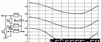
1. UMZCH on 6Zh1P and 6P14P has an output power of 3 W, sensitivity of 150 mV, and nonlinear distortion coefficient of 2.5%. The amplifier has a correction chain C7R6C5 for adjusting the HF tone.
Frequency response for 2 extreme positions R6
The output transformer is made on a Ш16x16 core, the primary winding contains 3500 turns of PEL 0.15 wire, the secondary winding contains 165 turns of PEL 0.64 for a load with a resistance of 4 Ohms.
2. The amplifier circuit below has the following characteristics: output power - 3 W, sensitivity - 100 mV, non-linear distortion factor - 1.5%. The amplifier is made using 6N2P tubes,
6P14P and has tone control for bass and treble.
The output transformer is similar to the previous design.
3. Below is a circuit diagram of a push-pull power amplifier. Its output power is 10 W with a harmonic distortion of 0.3%, sensitivity is 0.7 V.
The output stage of the amplifier is made according to an ultra-linear circuit and operates in AB mode. It must be taken into account that this class of amplifiers has more stringent requirements for output transformers and anode voltage filtering.
The output transformer is made on a Ш25x30 core. Sections of the primary winding Ia, Ig contain 850 turns of PEL 0.1 each, windings Ib, Ic contain 650 turns of PEL 0.1 each. The secondary winding contains 140 turns of PEL 0.64 for a load of 16 Ohms. Winding circuits for transformers for ultralinear amplifiers are given in specialized literature, also available here: Radio No. 4, 1958, p. 28.
4. The amplifier below has an output power of 12 W with a harmonic distortion at 1000 Hz - 0.4%. Amplifier sensitivity - 100 mV.
The output transformer is made on a magnetic core Ш25х30; to reduce the inductance between the windings, it is wound as follows:
The primary winding is divided into 6 parts of 500 turns of PEL 0.1. The secondary winding consists of two halves connected in series, consisting of two parallel-connected sections of 40 turns of PEL 0.64. In practice, the winding of the transformer is carried out as follows: first, sections 1-7-2-8-3 are wound, after which the frame is turned over and sections 4-9-5-10-6 are wound. Then the sections are connected according to the diagram in Figure (b).
5. The circuit of a 20-watt amplifier with a THD of 1.2% and a sensitivity of 0.5 V is shown below. The frequency response is uniform in the range 20 Hz - 20 kHz.
The output transformer is made on a Ш30x35 core. Windings Ia, Ib each contain 1200 turns of PEL 0.25, winding II contains 85 turns of PEL 1.0. Winding is carried out according to the rules for ultralinear UMZCH (see description above).
6. A two-channel tube power amplifier (4.5 W LF/KG - 3%, 3 W HF/KG - 2%, input voltage - 250 mV) is built on 3 lamps according to the following scheme:
The HF output transformer is made on a Sh12x16 core, the primary winding contains 1500 turns of 0.1 PEL, the secondary winding contains 56 turns of 0.51 PEL. The plates are assembled end-to-end with a gap of 0.1 mm. The LF output transformer is assembled on a USH 19x28 core. The primary winding contains 3000 turns of PEL 0.12, the secondary winding contains 52 turns of PEL 0.64 wire. The plates are assembled end-to-end with a gap of 0.12 mm.
V. Smirnov High-quality amplifier. - Radio, 1960, No. 9, pp. 45, 46
The author has proposed a circuit of an ultra-linear power amplifier with 5 lamps (monaural version) with an autotransformer output for a load of 4 and 16 Ohms. The use of an autotransformer simplifies the repetition of this design. The output power of the UMZCH amplifier is 12 W, the coefficient of nonlinear distortion is 3%, the sensitivity is 100 mV, the reproducible frequency band is 30...20000 Hz.
The first stage is made on a 6ZH1P high-frequency pentode to expand the amplifier's bandwidth towards HF. The second stage is a cathode follower made on “half” of a 6N1P triode. The output stage is assembled using 6P14P lamps using an anti-parallel circuit. The filter on elements R8C4R9C5 in the circuit is used to reduce interference from the electric motor of the record player - if repeated, it is not relevant at the moment.
The lamps should be powered from two transformers or from one but with insulated windings. Each rectifier must provide a current of up to 55 mA at a voltage of 250-300 V.
The output autotransformer is made on a Ш25x25 core. Sections I and I' each have 50 turns of PEL 0.9, II and II' each have 80 turns of PEL 0.9, III and III' each have 740 turns of PEL 0.31.
If you plan to use the amplifier with a different load, then the number of turns can be calculated using the formula:
A simple bass amplifier. - Radio, 1961, No. 9, p. 56
There is no separate bass reflex in the amplifier circuit; the output tubes themselves work as bass reflexes. The amplifier output power is 6 W.
Transformer Tr1 is selected with a power of 15 W, the primary winding is designed for an anode load resistance of 8 kOhm, the secondary winding for a load of 4 Ohms.
G. Krylov Modernization of a simple low-frequency amplifier. - Radio, 1962, No. 4 p. 52
The power amplifier circuit with 3 tubes (6Zh8, 6N9S, 6N5S) has a rated output power of 4 W, a reproduced frequency of 30..15000 Hz, and a nonlinear distortion coefficient of 1%.
The output transformer is assembled on a Ш-20 core, the thickness of the set is 20 mm. The first and third sections of the transformer contain 84 turns of 0.51 PE, the second - 336 turns of 0.35 PE. Winding order: First - Second - Third (see Radio, 1961, No. 1, p. 53, 54).
G. Krylov Broadband low frequency amplifier. - Radio, 1963, No. 11, pp. 37-39
Circuits of power amplifiers with a reproducible frequency band from 20 Hz to 20 kHz began to be published in USSR periodicals starting in the 60s of the 20th century. This was due to the development of broadcasting in the VHF range, which made it possible to broadcast programs in high quality.
One of the first schemes with high performance (for that time) was published in late 1963:
It should be noted that the magazine provides a detailed description of the manufacture and adjustment of the amplifier, which significantly increases the possibility of its successful repetition.
The output power of the amplifier is 7 W, the coefficient of nonlinear distortion is ~1%, the frequency of reproduced frequencies with a nonlinearity of no more than 1 dB is 20 - 20000 Hz, sensitivity is 0.2 V. The amplifier is designed to operate with a high-resistance load of ~300 Ohms. When using an autotransformer, you can also use regular 4..16 Ohm speakers.
For a 9 Ohm load, the autotransformer is made on the basis of the USH-16x32 core, winding I contains 500 turns of PEL 0.35 wire, section II - 110 turns of PEL 0.74.
Setting up the amplifier comes down to selecting the lamp mode (measured with a voltmeter with a high-impedance input of 20 MΩ/V). To ensure high amplifier performance, it is necessary to carefully select resistances R10, R17, R18, R19, R21, R22, R23 - selected in pairs for each stage with an accuracy of at least 5%.
E. Vaisman Elektrolina. - Radio, 1964, No. 8, p. 60
The amplifier circuit is taken from the general circuit of the Elektrolina electric musical instrument. The amplifier operates in ultra-linear mode, has an output power of 12 W and reproduces a frequency range from 40 to 15,000 Hz. The coefficient of dynamic distortion does not exceed 0.3%. The circuit uses an output transformer from the Festival radio receiver.
G. Krylov Low frequency amplifier. - Radio, 1966, No. 2, p. 28
The amplifier is made using 6N2P and 6S19P tubes and has a transformerless output, albeit for a high-impedance load. Connecting low-impedance speakers is possible via an autotransformer. The amplifier operates in the frequency range 20 - 20,000 Hz, has an output power of up to 3 W, and a nonlinear distortion coefficient at a power of 2 W of about 1%.
The autotransformer can be assembled on a Sh-16 core with a set thickness of 32 mm. Winding I contains 500 turns of PEL 0.33, winding II and III - 70 turns of PEL 0.51 each. Section II is wound first, then I and lastly III.
The original article can be downloaded here .
N. Zykov High-quality bass amplifier. - Radio, 1966, No. 4, 5, 6
The amplifier has an output power of 8 W, sensitivity - 100 mV - 10 V depending on the input type, nonlinear distortion coefficient at a power of 6 W - 0.2%, at maximum - 0.5%. The amplifier is designed for a load of 4 ohms and has a 5-band equalizer. The UMZCH uses: 3 6N1P lamps, 2 6P14P lamps. In fact, this circuit was the first publication of a high-quality amplifier in periodicals with a description of the design and the possibility of repetition by a radio amateur with average qualifications.
A detailed description of the design can be downloaded here .
N. Zykov Bass amplifier with expander. - Radio, 1966, No. 12
The amplifier is built on 6N2P, 6N1P tubes and has the ability to expand the dynamic range by 10 - 14 dB, which improves sound perception. The amplifier output power is 12 W, the reproduced frequency range is 30 - 18000 Hz, the sensitivity is 100 mV, the nonlinear distortion coefficient does not exceed 1%. The load can be a resistance of 1.5 - 9 Ohms.
A detailed description of the design can be downloaded here .
A. Slonim Two-channel amplifier. - Radio, 1967, No. 9, pp. 31, 54
The amplifier circuit proposed by the author has separate final amplifier stages for low frequencies (40 - 1000 Hz) and high frequencies (1000 - 15000 Hz). The amplifier is built on 4 tubes: 6Zh4 (6Zh1P), 6N9S (6N2P) and two 6N5S in the final stages. Each 6N5S can be replaced with two 6S19P. The amplifier is designed for a high-resistance load (150 - 550 ohms); a low-resistance load can also be used in conjunction with an autotransformer (see Radio, 1966, No. 2, p. 28). The amplifier sensitivity is 100 mV, output power is 3.5 W per channel.
Option for replacing output lamps with 6S19P
The description and configuration of the amplifier, as well as the power supply diagram, are given in the article .
G. Krylov Low frequency amplifier. - Radio, 1967, No. 3, p. 32
The author presents a circuit of a simple amplifier using three tubes: 6N2P in the preliminary amplification stage and 2 6P14P in the final stage. The amplifier output power is 6 W with a nonlinear distortion factor of 1%. Reproducible frequency - 30 - 15,000 Hz, sensitivity - 0.3 V.
The output transformer is made on an Ш26 core with a set thickness of 26 mm. The primary winding contains 2x1200 turns of PEV-2 0.19, the secondary winding contains 3x88 turns of PEV-2 0.47. The winding layout is shown in Fig. below:
You can read more about the amplifier
.
E. Zeldin Triode amplifier class B. - Radio, 1967, No. 4, p. 25, 26
The article presents two amplifier circuits using 6F1P and 6N6P tubes and 6N2P and 6N6P tubes. Output power 2.5 W (3 W at anode voltage 300 V), nonlinear distortion coefficient >4% (1% with the introduction of OOS). Reproducible frequency range - 40 - 15,000 Hz.
The output transformer is assembled on a Ш-12 core, the thickness of the set is 20 mm. The primary winding consists of two sections, each with 2300 turns of PEL 0.12, the secondary - 74 turns of PEL 0.74 (wound between the sections of the first winding).
For this circuit design, the output transformer is assembled on a Sh-12 core with a set thickness of 18 mm. The primary winding contains 2 sections of 1800 turns of PEL 0.13, the secondary winding contains 95 turns of PEL 0.59 for a load of 13 Ohms). The secondary one is wound in the same way as in the previous version between the sections of the first one.
A more detailed description is given here .
G. Krylov Low frequency amplifier. - Radio, 1968, No. 8, p. 41
The amplifier is built on 3 lamps (6Zh1P and 2x 6P15P) and has the following parameters: Output power 6 W with a harmonic distortion of 3% (with a power of 4 W, harmonic distortion is 1%), reproduced frequency range with unevenness of 1 dB - 25 - 16,000 Hz, sensitivity - 170 mV, noise level -55 dB.
Output transformer on a Sh-26 core with a set thickness of 26 mm. Primary winding 2x 1200 PEV-2 0.19 mm, secondary winding 3x 88 PEV-2 0.47 mm.
A. Mezherovsky Two-channel ultralinear amplifier. - Radio, 1968, No. 5, pp. 33-36
The author proposed a non-standard method for separating the LF and HF channels due to deep OOS.
The amplifier (in monophonic version) is built on tubes 6N2P .93 pieces) and 6P14P (4 pieces). It is designed for a maximum power of 7.5 W (per channel) with a maximum total harmonic distortion of no more than 0.85%. Nonlinearity of the frequency response in the range of 15 - 30,000 Hz is no more than 0.5 dB.
To calculate the secondary winding for a specific speaker, the article provides a formula.
↑ Power transformer data
Magnetic core USh16 X 24, winding / contains 2400 turns of PEV-2 0.13 wire, winding 11 - 270 turns of PEV-2 0.44 wire, winding /// - 68 turns of PEV-2 0.59 wire. If this block is supposed to power another device, for example the main low-frequency amplifier or radio receiver, then the data of transformer 77 can be as follows: magnetic circuit УШ26 X 28, winding / - 1040 turns of wire PEV-2 0.23, winding // - 145 turns of wire PEV-2 0.3, winding /// - 30 turns of wire PEV-2 1.0. The design of the power supply is arbitrary.
Circuit 1 transistor amplifier
The power supply is not critical here, you can easily supply the amplifier from 2x30 Volts to 2x60, only the output power will depend on this.
As for the transistors used in the project, they are not critical, you can use bd139 and bd140 instead of 2sc. Only one transistor should be used for thermal compensation purpose, as in the diagram. It's important to note that you shouldn't change the 2sc3964 because with others the quiescent current will rise quickly as the temperature rises.
It is assumed that the amplifier will be a budget version, because many do not even have a transformer with four secondary windings to power individual UMZCHs. In addition, current feedback amplifiers are not as susceptible to excitation.
Here, it is the operational amplifier that generates the sound of this amplifier. Using a less efficient op amp will usually result in degradation. After numerous experiments, we recommend choosing the JRC4580D.
↑ Setting up
Setting up an amplifier assembled from known good parts is not difficult.
After turning on the power and warming up the lamp for three to four minutes, a signal with a frequency of 1000 Hz and an amplitude of about 0.1 V is supplied to the input of the amplifier from the sound generator. Using the trimming resistor R6, equal amplitudes of the amplified signal are achieved at the bases of the transistors. The voltage amplitude is monitored using a voltmeter with a relative input resistance of at least 20 kOhm/V or an oscilloscope. If the output power of the amplifier is insufficient, then reduce the resistance of resistors R10 and R11. However, replacing them with resistors with a resistance of less than 100 Ohms is inappropriate, since this sharply increases the current flowing through the transistors. Next, the main parameters of the amplifier are checked using one of the methods that have been repeatedly published on the pages of Radio magazine. If a radio amateur does not have the necessary measuring instruments, the quality indicators of the amplifier can be assessed by ear by applying a signal from a stereophonic electric player or tape recorder to its input.
Transistor amplifier circuit 2
And this is a similar AF amplifier, but in a slightly more complex version. The circuit is essentially the same, only there is an additional set of protections; here the power does not control the relay, but only activates the stabilizers, thereby implementing delayed activation of the amplifier after power is applied. In this way the safety action is carried out. Photo of the device:
A session of warm lamp “magic” with exposure
Despite the somewhat subsided interest of many audiophiles and music lovers in tube amplifiers, debate about the advantages/disadvantages of these archaic centenarians continues to this day. Conventionally, those arguing about TLZ can be divided into two camps. The first are adherents of progress, who believe that tube technology belongs in the dustbin of history or, at best, in some technical museum. The second is ardent supporters of warm tube sound, who see and hear in tube UMZCHs (certainly single-ended, without OOS, A class) the opportunity to receive a “spiritual revelation” and “truly” beautiful (TRUE, airy, etc.) sound.
Fierce battles between lovers and haters of lamps lead to bouts of discussion hypersalivation, failure of keyboards, and violent eruption of words on the relevant forums. In addition to these warring parties, the topic of tube UMZCHs is of interest to people who do not discuss it - these are: radio amateurs who create these amplifiers and “not true” audiophile comrades who are satisfied with the features of the existing equipment outside the paradigm of searching for uncompromising sound.
I doubt that my post will put an end to the debate about TLZ, but I will try to shed a ray of light on the “mysterious,” “metaphysical” “phenomenon” of “living” TLZ. I am neither an ardent hater nor an ardent supporter of uncompromising warm tube sound, but as a listener I often feel a significant difference between transistor/integrated and tube amplified circuits. The question of the origin of this difference is really interesting to me. Semi-metaphysical and marketing explanations do not suit me much, so I decided to present in a structured manner everything that I was able to find about the so-called TLZ in one short post.
The history of lamp “magic”
Since the birth and mass distribution of transistor technology, the concept of “dead”, “cold” transistor sound has appeared, the reasons for which can be found in detail here.
Transistor amplifiers have come a long way since their inception, and, thanks to improvements in circuit technology, the phenomenon of “transistor sound” has ceased to exist. At the same time, many interested people noted that, all other things being equal (SOI, frequency response, source, path, etc.), the same work, when played on tube and transistor UMZCH, sounds differently. This difference, as well as the somewhat tarnished reputation of transistor devices, were the reasons for the idea of the superiority of lamps, the formation of the concept of TLZ, as well as numerous speculations on the lamp topic.
The increase in mass production of inexpensive integrated amplifiers and AV receivers, with a decrease in their cost (and, accordingly, the quality of the element base), has strengthened the opinion of some audiophiles about the unsuitability of transistor systems. This phenomenon became known as the renaissance of tube technology in the late 90s and early 2000s.
Manufacturers did not stand still, the quality of transistor and digital solutions was growing, while prices for warm lamps were biting with the frenzy of American bulldogs. The latter circumstance made the lamps interesting only to a narrow circle of fanatical seekers of impeccable sound, very rich people and amateur radio enthusiasts.
Tube “magic” in psychoacoustics and circuitry
Psychoacoustics of TLZ
When we talk about TLZ, we mean the timbral features of the reproduced sound, i.e. so-called "coloring". In fact, “coloring” is nothing more than harmonic distortion + characteristic features of the frequency response graph. It is impossible to completely get rid of distortions, but it is possible to reduce their presence in the spectrum to the minimum values at which a person will not perceive them. In the case of tube amplifiers, these are predominantly even harmonics. It is known that people perceive even harmonics as more euphonious (pleasant to the ear) distortions. At the same time, in transistor amplifiers, the SOI is, as a rule, significantly lower, which indicates higher fidelity of reproduction.
It is precisely due to the large number of even harmonics in the spectrum that tube amplification is actively used for guitar equipment. There, distortion allows you to create the desired sound (i.e., in fact, the amplifier is part of the instrument). At the same time, their presence in sound-reproducing equipment is considered by many to be a disadvantage, since the equipment must reproduce what is recorded as accurately as possible, and not distort (embellish, change). Others, on the contrary, consider this effect to be an advantage, due to the euphony of such distortions.
It should also be noted that the human ear perceives harmonics of different orders differently. Scott Frankland, Irina Aldoshina, Alexander Voishvillo and other wonderful people who have conducted research on this topic write that the higher the harmonic, the more noticeably it affects perception and the worse a person subjectively evaluates the sound. For example, even professional experts cannot hear 1% of the second harmonic, but in the range of 1.8-3.5% the second harmonic is detectable by most people. At the same time, a tenth is noticed already in the presence of 0.1%.
Psychoacoustic studies have revealed that: “The auditory noticeability of any harmonic is directly proportional to the square of its number”
A characteristic feature: in the signal spectrum of tube amplifiers there are no more than five harmonic components, which is significantly less than in the spectrum of transistor devices (where the 9th, 11th and other high harmonics often “leak” into it).
It was also found that the presence of some harmonics can mask others. For example, the presence of the second harmonic hides the third from perception. These studies led to the conclusion that the most harmonious for human hearing is a combination of harmonics that gradually decrease in level (the second is large, the third is less than the second, the fourth is less than the third, etc.). This is exactly what happens with harmonics when using tube UMZCHs.
Brief information about the circuit design of TLZ
“Magically” correct, from the point of view of circuit design, are considered single-ended circuit breakers without OOS. The linear characteristics of tubes are better than those of semiconductors. The absence of negative feedback allows you to prevent the appearance of a significant amount of intermodulation distortion. For the same purpose, in tube amplifiers created within the framework of this philosophy (there is no other way to call it), they refuse to install switching power supplies (according to a number of authors, the use of pulses leads to an increase in IMD and the appearance of background). In most cases, another means of change (euphonious distortion) are powerful output transformers, which, often, reduce the linearity of the frequency response, emphasizing the mid frequencies.
But this is in theory, but in practice... “thanks to” these solutions, many HI End lamps go on sale with an IMD level of more than 7-10%, and the THD (harmonic distortion factor) can reach 3-5%, which does not even correspond to classic Hi-End lamps. Fi standard. Enough has been written about the typical disadvantages of single-cycle circuits and the lack of environmental protection: efficiency, heat generation (in the literal sense), energy consumption, high mass, low power - these are “sacred” sacrifices to the “divine sound”.
It turns out that the lamp “ennobles” the sound, but does this due to the spectral composition and characteristics of harmonic distortions, as well as controversial circuit solutions that change the frequency response and timbral features. Those. in fact, it turns out that for the user of a “warm lamp”, in addition to other sound properties, what is important is not the fidelity of reproduction, but the presence of euphonious distortions. This is the stumbling block in disputes about such UMZCH.
The bottom line is that the legendary TLZ is:
- Saturation of sound with even harmonics;
- Limited order of the fifth harmonics;
- Gradual decrease in level in the spectral combination of harmonics (the higher the order of the harmonics, the lower the level)
- The presence of characteristic features of the frequency response due to the use of an output transformer;
That's all the magic. And yes, this is a really beautiful sound, if this word is applicable to sound-reproducing equipment... Beautiful, “warm”, but for the most part, less accurate.
Bottom line
The essence of TLZ is in very specific, typical features of the change (processing, distortion) of the signal.
Criticism of transistor amplifiers should remain in the distant seventies, since high-quality examples of this technology are in no way inferior to lamps, and sometimes significantly superior (at the same cost), fortunately the stones have been in use for more than 40 years. Tube UMZCHs are archaic from the point of view of circuitry and HI-FI philosophy, but they represent high subjective value for people with certain taste preferences. It’s not time for tubes to be scrapped, because, despite the possibility of full digital emulation of TLZ effects (proven by guitar equipment), manufacturers are focusing on the production of TRUE LUMZCH, guessing the expectations of traditionalists from audio. In addition, lamps are the subject of interesting experiments and experiments by radio amateurs creating sound equipment.
Everyone decides for themselves which amplifier to choose, and the final word always remains with subjective perception.
I will be glad to have a lively and correct discussion on the topic.
