↑ Selection of circuit solutions
Based on the numerous experience of senior comrades in the lamp workshop, it was decided to take as a basis the well-known scheme of the respected Anatoly Iosifovich Manakov (aka Gegan) and quickly sketch out a layout.
Some questions arose here. The fact is that with different signal sources (and there were CDs, including those released in the last century, and DVDs, and the Japanese cassette decks of the 70s of the last century, which became classic, and even the output from a PC audio card), the cascade sounded differently. Everything was fine with modern signal sources, but he was not entirely in agreement with some distinguished veterans of respected foreign companies (in order not to offend fans of famous brands and not to cast a shadow on distinguished foreign manufacturers, we will not name their names). Aurally, there was some loss of dynamic range and a tightness of the overall audio scene.
After analyzing the situation, it was concluded that not all output stages of signal sources, even with low output impedance, are capable of operating a rather complex complex load, which is the Baxandal passive bridge tone control, especially those that have an initially low current rest, and possibly low load capacity. To be fair, it must be said that the values of the variable resistors were reduced to 100k (according to the original MAI circuit 200...220k), simply because they were available.
So, you need a buffer stage with good load capacity, low output resistance, a quiescent current of at least 8-10 mA, good pulse response and low harmonic distortion. We take the same lamp as in the original circuit, 6N23P. Despite the large number of controversies surrounding its use in audio technology, I believe that its use is quite justified in many practical cases, including this one specifically.
We don’t skimp on lamps, given their cheapness and availability; we install a White repeater at the input, one lamp at the input of each channel, a voltage amplifier at the output, a total of three 6N23P double triodes, inexpensive and cheerful.
↑ Why White's repeater?
1) Unlike a conventional cathode follower with a transmission coefficient of about 0.7...0.8, here we already have 0.96 and the ability to obtain an overall transmission coefficient of about 1.0 (the attenuation in the passive RT is compensated by the output stage of the UN).
2) Due to the presence of positive feedback in the White follower, we have a reduced output resistance compared to a simple cathode follower.
3) With an “optimized” positive feedback value, we obtain a small harmonic distortion coefficient and a “live” natural sound. Again, we are not inventing anything new; everything has long been invented and optimized by famous audio gurus, such as John Bruschi and his associates, who have repeated this design several times.
↑ Loudness compensation
Well, what about loudness compensation? Especially in moderation? Again we turn to the classics, “Iron Shikhman”. This picture can be found on more than a dozen domestic and foreign sites. Let's look:
It was decided to place this volume control on a resistor with one tap at the input after the switch. In fact, the load is also “not sugar”; we need to check how it behaves after everything has already been done on tested signal sources. It turned out that it was quite decent, so we finished the prototyping and drew a diagram.
Tube stereo preamplifier switcher
The amplifier described here is a system quite similar in function to current amplifier-switching devices. The need for such an amplifier may arise in two cases: if a radio amateur has “active” electro-acoustic units containing a powerful final amplifier with its own power supply, and if a complete audio complex is created, including sources with different output signal parameters - tape recorder, TV, players with dynamic and piezo heads pickup, laser players, stereo tuner, multi-program wire broadcast line, etc.
This amplifier was created precisely for this (second) case. With its help, you can carry out the necessary switching on a single control panel and bring the most diverse signals to a common denominator.
This common denominator means both leveling their levels and frequency correction, the need for which arises when using long shielded lines from sources located in different places in the room.
Before moving on to the description of the amplifier, we will make a reservation that everything said applies only to one of the two channels of the stereo amplifier, therefore, when assembling the amplifier, arranging its components, manufacturing printed circuit boards or selecting switching units, you need to remember that there will be two channels, and you should make appropriate decisions taking this into account. This must be taken into account when choosing or manufacturing a power transformer, as well as rectifier elements. In addition, it is completely unacceptable that after the adjustment is completed, all parameters of one channel, without exception, differ from similar parameters of another channel by more than 1...2%.
So, the amplifier begins with an 8-position switch, assembled on a P2K type switch and designed to switch the following audio signal sources: 1. Dynamic microphone 2. Dynamic head of a stereo player. 3. Piezo head of a stereo player. 4. Laser disc player. 5. Stereo tape recorder. 6. Stereo UKZ tuner or AM/FM receiver. 7. TV. 8. Three-program radio broadcast network.
Connection of sources to the switch is carried out using standard 5-pin cylindrical connectors. Each of the signals (except for the signal from the microphone) goes to its own resistive divider, the lower arm of which is made variable. The upper-side resistor is blocked by a capacitor, the purpose of which is to compensate for the attenuation of the high-frequency part of the spectrum in a long line. The nominal value of this capacitance is selected experimentally, since line losses cannot be accurately determined. How this is done will be discussed further.
The corrected signal is fed through another group of contacts to the lamp grid of the first stage of a two-stage voltage preamplifier. Here, at the amplifier input, there is a fine-compensated volume control.
Between the first and second stages there is a two-band tone control, which separately regulates the sections of the spectrum above and below the crossover frequency - 1000 Hz. This two-band regulator can be replaced without any changes in the circuit by the clang register and the four-band regulator used in the previously described high-end amplifier.
The signal from the microphone, before reaching the input of the first stage, is pre-amplified by an additional microphone stage. The cascade is assembled on a low-noise pentode type EF-86 (complete domestic analogue - 6Zh32P). This lamp was once used in some domestic tape recorders (for example, Yauza). The installation features of this cascade will be discussed in more detail below.
After amplification by the second stage, the signal removed from the anode of the second triode is divided into two: one goes to the grid of the first terminal stage - a cathode follower, assembled on one half of the 6N6P double triode (VLZ in the diagram of Fig. 34), the other - to the grid of the additional amplifier lamp voltage VL2 6СЗП or 6С4П, after amplification of which the signal enters the input of the second terminal triode - cathode follower VLЗ 6Н6П. To save the total number of tubes in the amplifier, instead of two 6SZP (or 6S4P) tubes in two channels, it is permissible to use one dual triode of the 6N1P type - one triode for each channel. In this case, it is necessary to use an antiphonal filament circuit for powering this lamp with a constant voltage with additional feed (+15...25 V), as was done in a high-end amplifier.
Thus, any input signal, before entering the grid of one of the final cathode followers, is amplified in one case by a two-stage, in the other by a three-stage preamplifier. This is done in order to be able to simply press the output switch button to change the overall gain of our ultrasonic sounder by n times, where n is the real gain of the additional stage on the VL2 lamp. In the process of adjusting the amplifier, its value is selected equal to 10, 20 or 50 and, accordingly, two switch buttons n are marked “x1” and “x10” (or 20 or 50).
The output stages are assembled according to the cathode follower circuit, which have a very low output resistance. This is necessary so that when the signal passes from the output of the preliminary ultrasonic amplifier to the input of a powerful final amplifier, there are no additional losses and distortions in the high-frequency part of the spectrum, especially if the connecting lines are long enough.
Let's return to the additional microphone amplifier. It is included in the ultrasonic circuit so that, if desired, it is possible to implement a rather fashionable “karaoke” function, which allows solo accompaniment of any phonograms (from disks or magnetic media). Instead of one, three microphones can be included at the input, which will expand solo possibilities to choral ones.
The microphone stage has its own independent volume control, which allows mixing of its own and accompanying music signals within a wide range. The complete diagram of this cascade is shown in Fig. 35.
Strictly speaking, the microphone stage does not have to be tube-based. Today, there are circuits of many microphone amplifiers based on transistors and microcircuits that have excellent characteristics, are low-noise and do not, like tube ones, have a tendency to produce a microphone effect. However, their use will entail the need to introduce an additional low-voltage rectifier with good filtering into the overall power circuit, so as a result, the overall gain from using a transistor microphone amplifier may be insignificant or even zero.
And one more caveat. The amplifier circuit provides an input from a radio broadcast line, which today is available in almost every city and even regional center. In large cities, this broadcast is multi-program and includes stereo transmissions. If such wired broadcasting exists in your city, it is advisable to introduce an additional unit into the amplifier circuit - a three-program broadcast decoder with a stereo output. There is no point in describing the diagram of such a unit and its design: it is standard and has been published several times (for example, in the Radio magazine). We only note that if it is used, it is advisable to immediately replace the 8-position switch of the input switch with a 10-position one and switch the signals from each of the three broadcast channels according to the same principle as for one channel. To switch broadcast channels, you can also introduce an additional three-position flip or push-button switch.
That's probably all that concerns the amplifier circuit. Its structural design depends 100% on where and how it will be placed - as part of a music center, as a separate device, on a separate table, on a cabinet shelf or next to the final amplifier and other equipment of the complex.
Let us present one of the many possible options, in which the amplifier is designed as an autonomous control unit for all devices of the audio complex. Unlike the previously described high-end amplifier, this amplifier is quite compact and lightweight. In this regard, it was necessary to abandon the horizontal placement of the switch-switch on the front front panel, since when you press the switch buttons, the entire amplifier block can be moved across the table.
The switch is positioned vertically and is located on the front of the amplifier's top panel. All operational controls are also located there - volume, tone, stereo balance, microphone mixer controls. The appearance of the amplifier is shown in Fig. 36, and the control panel is in Fig. 37. The amplifier is placed on one common printed circuit board shown in Fig. 38, in fig. Figure 39 shows the placement of parts and circuit elements on the board.
The power transformer and rectifier parts are assembled on a frame base, the dimensions of which are not critical and must be determined by the designer himself based on the number of switched sources, the presence or absence of a microphone amplifier, a wired stereo broadcast decoder unit and other factors.
In the author’s design, above each switch button in the top panel, holes are drilled into which red LEDs are inserted from the inside, which are connected when the corresponding button is pressed to a 12 V voltage source and indicate that a particular device is connected to an amplifier. This system is not shown on the amplifier diagram, since formally it has nothing to do with it. If desired, any radio amateur can easily do it on his own.
ADJUSTMENT AND ADJUSTMENT
Let's look at adjusting the amplifier. First, with the lamps removed, the operation of the rectifiers and the presence of voltage on the electrodes of all lamps, including the filament circuits, are checked. If everything is in order with this, all the lamps are installed in place and after warming up the lamps (about 1 min), check the established voltage values on the anodes and cathodes of all lamps, as well as on the shielding grid of the microphone stage lamp. These values should not differ from those indicated on the diagram by more than 5...10%.
After this, a low-level signal with a frequency of 1000 Hz (20...50 mV) is supplied to the grid of lamp VL1 (Fig. 34) from the sound generator. This is done so that any voltage convenient for reading is established at the output of the first cathode follower (for example, 0.1 or 0.5 or 1 V). Then the voltmeter is switched from the output of the first cathode follower to the output of the second, the decade switch at the output of the sound generator reduces the output voltage by 10, 20 or 50 times, without touching the knob of the smooth output voltage regulator, and by rotating the setting potentiometer R20 at the output of the second repeater, this is achieved the same output voltage as at the output of the first repeater. After adjustment, without changing the input signal level, make sure that the output signals on both repeaters differ exactly by the number of times you select (10, 20 or 50), the designation of which is applied with paint, engraving or decalcomania to the output switch buttons: “x1” and “ x10" (or, respectively, "x20" or "x50").
Having finished with this, proceed to the main part of the adjustment - leveling signal levels from various sources and correcting the frequency response of connecting lines. The method of such adjustment depends to a large extent on whether you will be able to obtain (purchase, rent, rewrite) standardized sources of sound signals during this work.
Such sources at enterprises engaged in the production, repair or operation of sound-reproducing equipment, as well as at radio centers and in sound recording houses (studios), are test records and magnetic test films (on cassettes), on which, instead of music programs, pure recordings are recorded in compliance with GOST requirements. tones of the full frequency range of the sound spectrum from 20 Hz to 20 kHz. Each of these frequencies is reproduced by a real source for 20...30 s. During this time, you need to have time to measure the voltages at the output (or input) of the amplifier and write down these values, and then build a graph of the frequency response from them.
This method is the most accurate and reliable, as it takes into account the degree of influence on the general characteristics of all elements of the sound reproduction path.
If you are unable to purchase test plates or test films, you will have to use the second method, although not as accurate, but quite accessible. It consists in the fact that instead of test records and test films, the same sound generator is used.
Before you start making adjustments, you need to set the tone controls to a position that corresponds to the linear frequency response. To do this, first set both tone controls to approximately the middle position. During this and all subsequent operations, the volume control should be in the maximum volume position (all the way clockwise), and the stereo balance control should be in the middle position.
A low-level signal with a frequency of 1000 Hz is supplied to the amplifier input so that a voltage convenient for measurement is established at the amplifier output (for example, 0.5 V). Then, keeping the generator voltage constant, switch the frequency to 100 Hz and by rotating the low-frequency regulator, achieve the same voltage at the output as at a frequency of 1000 Hz. After this, the position of the high-frequency control is similarly clarified, but at a frequency of 10,000 Hz. Finally, it is advisable to “walk” across the entire spectrum from 20 Hz to 20 kHz to ensure that the output voltage remains relatively equal at all frequencies within the spectrum.
Having set all the controls to the desired position, we begin to adjust the switching part of the amplifier, which is best started from the source with the lowest output voltage (excluding the microphone). In our list, such a source is most likely the electrodynamic pickup head of a regular (non-laser) disc player.
Press the "Dynamic Head" button on the signal switch and take the sound generator to where the record player is located. The signal from the generator must be fed directly to the beginning of the cable or shielded line connecting the player to our amplifier. Let us emphasize once again: not to the input of the amplifier, but to the output of the pickup, so that the entire connecting cable is between the generator and the amplifier. And one more very important reminder: the output resistance of the generator must be equal (or have the same order of magnitude) to the internal resistance of the source. This means that if the internal resistance of the dynamic cartridge is several hundred ohms, then the oscillator output impedance switch should be set to the position closest to the internal resistance of the source. If the signal source is a piezo pickup head, which has an internal resistance of approximately 0.5 MOhm, then a constant resistor of the same resistance must be connected in series between the generator output and the beginning of the connecting line.
To make it easier to navigate the output resistances of various signal sources, in Table. 2 shows their generally accepted standardized values. It also gives the average values of the output voltages of these sources at a frequency of 1000 Hz.
Now apply a 1000 Hz signal to the input of the connecting line (with the pickup head turned off!) at a level that is nominal for this source (Table 2), connect a tube voltmeter to the output of the first cathode follower (“x1”) and rotate the setting potentiometer To 16 (in the diagram, Fig. 33) until a certain voltage is obtained at the output, taken as nominal, say, 0.5 or 1 V.
After this, with a constant signal level from the generator, switch the frequency to 10 kHz. This will certainly lead to some reduction in the output signal level, if, of course, you set the tone and volume controls correctly. In order to restore a signal with a frequency of 10 kHz to the previous level, you will have to experimentally select the capacitance of the SI capacitor connected in parallel with the resistor K 15. At this point, the adjustment of the first of eight (or ten) lines can be considered complete. The next channel is regulated in the same way (in our case, a piezo pickup), but now a different signal level and a different series matching resistor are set at the input of the line in accordance with the table for this source. At the same time, the output signal level at the first cathode follower must remain unchanged for all sources, which is achieved by adjusting the setting potentiometers and selecting the capacitances of the compensation capacitors.
If all adjustments are made in accordance with the recommendations given and the data obtained coincide with the nominal ones, the adjustment of one channel can be considered complete. The easiest way to verify this is by connecting the output of our ultrasonic frequency amplifier to the input of any final amplifier with an acoustic system (up to the “adapter” input of a conventional radio receiver, if there is one), and at a certain average sound volume, alternately using the switch switch, feeding real phonograms from all switched sources. In this case, the sound volume should be perceived by ear as relatively identical, with minor deviations determined by the plot of the phonograms. If the signal from one of the sources differs in sound volume from the others or reveals a clear “blockage” in the characteristics from the high frequencies, you should once again return to adjusting this particular channel. It is possible that during the adjustment process you missed this particular channel or supplied a signal from this source “to the wrong” line.
Let's return to the microphone stage. If it is made on a lamp, try, if possible, to purchase an EF-86 lamp made in any European country (Germany, Czechoslovakia, Poland) or the USA. It was produced by many companies under various trade names: EF-86, E-7027, E-7108, EF-806S, EF-866, Z-729, 6VK8, 5928, 6267. As for the domestic analogue 6Zh32P, it is significantly inferior to Western lamps , at least in two very significant parameters: the level of its own background from the filament circuit and the tendency to the microphone effect. And if the first can still be eliminated by powering the lamp filament with a well-filtered direct voltage, then to prevent the microphone effect one cannot do without a “soft” suspension of the lamp (together with the socket) on an annular rubber gasket-damper.
In order to extremely reduce the possibility of hum from the filament circuit, the microphone amplifier, as a rule, is made with a grounded cathode, and automatic bias in this case is achieved due to a small grid current in the presence of a signal. It is for this purpose that the resistance of the grid leakage resistor is chosen to be very large (in our case, 5.1 MOhm). This does not lead to noticeable harmonic distortion if the input signal level is low enough.
The electrical mode of the microphone stage lamp is the least critical, since the levels of input signals from the microphone are very low, and the anode current under any circumstances does not go beyond the linear section of the anode-grid characteristic in its upper part.
However, if, when setting up the amplifier, you hear distortion when operating from the microphone, it would not hurt to take the dynamic characteristics of the cascade “point by point” and, if necessary, change the position of the operating point by selecting the resistance of the grid leakage resistor or the resistor in the shielding grid circuit. Since domestic resistors of large values tend to “lose” their resistance almost to infinity over time, we recommend that instead of one 5.1 MOhm resistor in the lamp grid circuit, install two parallel-connected resistors with resistances of 10 MOhm each.
And finally, about communications. This question is quite serious, since we are talking about long connecting lines subject to various external interference (for example, from a power network running parallel to a 220 V line). In addition, we are dealing with the transmission of very low level signals (5...200 mV) and, moreover, from sources with high internal resistance (up to hundreds of kilo-ohms).
These two factors require the use of special measures to prevent interference and interference with the useful signal from the outside and to eliminate the mutual influence of lines from different sources. The situation is aggravated by the fact that different signal sources require different circuit solutions. We will try to give recommendations for each individual case.
Three lines are most vulnerable: from the dynamic pickup head, piezo pickup and microphone. For these three sources, one general solution can be proposed: take a thin coaxial cable (for example, types RK-50-2-13 (old name RK-19), RK-50-3-13 (RK-55), RK-50- 2-21 (RKTF-91) or RK-75-2-21 with an outer diameter of 4...5 mm and a linear capacitance of 70...115 pF/m) of double length (for each of the switched sources, except for the microphone) and place two pieces of cable the required length into one common metal braid, as shown in the figure.
It is desirable that this common braid is also insulated, for which it is best to extend the entire workpiece into a vinyl chloride tube. To make this process as easy as possible, the tube can be cut into several pieces 0.5...1 m long and put on alternately.
Wiring of cables from the source side and from the amplifier input side should be done as shown in Fig. 41. For a microphone, since it will most likely be monophonic, there is no need for two separate cables, however, using the cable braid as the other (neutral) wire is unacceptable here due to the inevitable occurrence of hum. For a microphone line, if it is more than 1 m, you will have to make a homemade cable from two separate wires - signal and neutral, which should be placed in a common shielding braid. The connection of both wires and braid can be seen in Fig. 40.
The connecting lines for the stereo tuner, stereo tape recorder and stereo laser disc player can also be made of the same type, but slightly different. Here, three multi-colored wires must be pulled into one common shielding braid: two signal wires for the left and right channels (for example, green and blue) and one thicker one (black or white) for the common “ground”. It is advisable to place this cable together with the braid in a vinyl chloride stocking.
The signal from the TV can be transmitted over a regular standard single coaxial cable, using its braid as a neutral wire, since the background level of the TV itself does not allow us to talk about truly high-quality sound reproduction. It should be borne in mind that the audio signal can be removed both from the output of an ultrasonic TV (from the speaker terminals) and from the load of the frequency detector. In the first case, we will be dealing with a low-impedance output (units of ohms), and, therefore, the connecting cable will be practically not affected by external interference and will not create additional losses in the high-frequency part of the spectrum.
In this case, firstly, the level of the output signal will completely depend on the position of the TV volume control and, secondly, it will not be possible to reproduce sound only through an amplifier, without the obligatory sound of the TV itself. In addition, in this case we will receive a signal that has already been pre-distorted by the low-frequency amplifier of the TV, which, as a rule, is not of high class.
It is better to use the second method and remove the signal directly from the output of the frequency detector. To do this, you will have to connect the signal from the detector to an additional connector, which can be installed on the supporting frame of the TV or, in extreme cases, on a removable back wall. Connect the connecting line to this connector using a plug. In this case, the connecting line must also be made shielded, with two separate wires.
And finally, about the last connecting line - from the radio broadcast network. The features of this line are determined by two factors. The first is that inside the living room, neither of the two wires is “zero” - they are both equivalent and each of them can be considered a signal wire. Therefore, in the switch, in the circuit of each of the two wires (including the one that is grounded), ballast resistors are connected in series (R1 and R2 in the diagram in Fig. 33). In this case, signal loss can be neglected, since the signal level in the line is one or two orders of magnitude higher than from other sources. That is why the switch switch has an additional group of contacts that “grounds” the signal from the broadcast line in all positions except the last eighth (or the last three, if there are ten in total), in order to avoid noticeable interference from the broadcast program when working from other sources.
The second consideration is only relevant if the broadcast line is multiprogram. As is known, signals from additional channels are transmitted at fairly high ultrasonic frequencies (19 and 38 kHz), which makes capacitive losses in the additional connecting line very significant. That is why it is better to make the broadcast line not shielded, but to use an ordinary thin double network wire in vinyl chloride insulation or a telephone wire (but only multi-core, since single-core easily and quickly breaks off). To exclude noticeable interference from this line to all the others, it is advisable to conduct it not in a common beam with other lines, but separately and at some distance from the others.
List of radioelements
| Designation | Type | Denomination | Quantity | Note | Shop | My notepad |
| Pre-amplifier-switcher. | ||||||
| Radio tube | EF-86 | 2 | Analogue 6Zh32P | Search in the Otron store | To notepad | |
| Radio tube | 2 | Search in the Otron store | To notepad | |||
| C1, C2 x2 | Capacitor | 0.05 µF | 4 | Search in the Otron store | To notepad | |
| C3, C4 x2 | Capacitor | 0.1 µF | 4 | Search in the Otron store | To notepad | |
| C5-C11 x2 | Capacitor | 14 | Search in the Otron store | To notepad | ||
| R1, R2 | Resistor | 1 kOhm | 2 | There is no stereophonic radio network | Search in the Otron store | To notepad |
| R3, R5, R7, R9, R11, R13, R15, R17 x2 | Resistor | 470 kOhm | 16 | Search in the Otron store | To notepad | |
| R4, R6, R8, R10, R12, R14, R16 x2 | Trimmer resistor | 470 kOhm | 14 | Search in the Otron store | To notepad | |
| R18 x2 | Variable resistor | 470 kOhm | 2 | Search in the Otron store | To notepad | |
| Resistor | 10 | Search in the Otron store | To notepad | |||
| SA1-SA4 | Switch | P2K | 8 | Search in the Otron store | To notepad | |
| 5 pin barrel connector | 8 | Search in the Otron store | To notepad | |||
| Audio amplifier. | ||||||
| VL1 x2 | Radio tube | 6N2P | 2 | Search in the Otron store | To notepad | |
| VL2 x2 | Radio tube | 6S3P | 2 | Search in the Otron store | To notepad | |
| VL3 x2 | Radio tube | 6N6P | 2 | Search in the Otron store | To notepad | |
| C1, C7, C13, C14, C17, C18 x2 | Capacitor | 0.1 µF | 12 | Search in the Otron store | To notepad | |
| C2 x2 | Capacitor | 6800 pF | 2 | Search in the Otron store | To notepad | |
| C3, C10 x2 | Capacitor | 51 pF | 4 | Search in the Otron store | To notepad | |
| C4, C8 x2 | Electrolytic capacitor | 30 µF | 4 | Search in the Otron store | To notepad | |
| C5, C6 x2 | Capacitor | 0.05 µF | 4 | Search in the Otron store | To notepad | |
| C9 x2 | Capacitor | 1000 pF | 2 | Search in the Otron store | To notepad | |
| C11 x2 | Capacitor | 0.01 µF | 2 | Search in the Otron store | To notepad | |
| C12 x2 | Capacitor | 2000 pF | 2 | Search in the Otron store | To notepad | |
| C15, C16 x2 | Electrolytic capacitor | 50 µF | 4 | Search in the Otron store | To notepad | |
| R1, R10, R19 x2 | Resistor | 220 kOhm | 6 | Search in the Otron store | To notepad | |
| R2 x2 | Resistor | 820 kOhm | 2 | Search in the Otron store | To notepad | |
| R3 | Dual variable resistor | 2.2 MOhm | 1 | Search in the Otron store | To notepad | |
| R4, R7, R27, R28 x2 | Resistor | 1 kOhm | 8 | R27 and R28 0.5 W | Search in the Otron store | To notepad |
| R5, R6, R15 x2 | Resistor | 100 kOhm | 6 | Search in the Otron store | To notepad | |
| R8 x2 | Resistor | 470 kOhm | 2 | Search in the Otron store | To notepad | |
| R9, R17 x2 | Resistor | 22 kOhm | 4 | R9 0.5 W | Search in the Otron store | To notepad |
| R11 x2 | Resistor | 330 kOhm | 2 | Search in the Otron store | To notepad | |
| R12, R16 | Dual variable resistor | 1 MOhm | 2 | Search in the Otron store | To notepad | |
| R13 x2 | Resistor | 12 kOhm | 2 | Search in the Otron store | To notepad | |
| R14 x2 | Resistor | 20 kOhm | 2 | Search in the Otron store | To notepad | |
| R18 | Variable resistor | 1 MOhm | 1 | Search in the Otron store | To notepad | |
| R20 x2 | Trimmer resistor | 47 kOhm | 2 | Search in the Otron store | To notepad | |
| R21 x2 | Resistor | 200 Ohm | 2 | Search in the Otron store | To notepad | |
| R22 x2 | Resistor | 75 kOhm | 2 | 0.5 W | Search in the Otron store | To notepad |
| R23 x2 | Resistor | 10 kOhm | 2 | 0.5 W | Search in the Otron store | To notepad |
| R24, R31 x2 | Resistor | 750 kOhm | 4 | Search in the Otron store | To notepad | |
| R25, R29 x2 | Resistor | 560 Ohm | 4 | Search in the Otron store | To notepad | |
| R26, R30 x2 | Resistor | 2.7 kOhm | 4 | 0.5 W | Search in the Otron store | To notepad |
| Switch | P2K | 2 | Search in the Otron store | To notepad | ||
| Microphone amplifier. | ||||||
| VL1 | Radio tube | EF-86 | 1 | Analogue 6Zh32P | Search in the Otron store | To notepad |
| C1 | Capacitor | 0.047 µF | 1 | Search in the Otron store | To notepad | |
| C2, C5 | Electrolytic capacitor | 30 µF | 2 | Search in the Otron store | To notepad | |
| C3 | Capacitor | 1 µF | 1 | Search in the Otron store | To notepad | |
| C4, C7 | Capacitor | 0.1 µF | 2 | Search in the Otron store | To notepad | |
| C6 | Electrolytic capacitor | 1000 µF | 1 | Search in the Otron store | To notepad | |
| R1 | Resistor | 5.1 MOhm | 1 | Search in the Otron store | To notepad | |
| R2 | Resistor | 15 kOhm | 1 | Search in the Otron store | To notepad | |
| R3, R5 | Resistor | 150 kOhm | 2 | Search in the Otron store | To notepad | |
| R4 | Variable resistor | 470 Ohm | 1 | Search in the Otron store | To notepad | |
| R6 | Resistor | 750 kOhm | 1 | Search in the Otron store | To notepad | |
| R7 | Variable resistor | 1 MOhm | 1 | Search in the Otron store | To notepad | |
| R8 | Resistor | 10 kOhm | 1 | Search in the Otron store | To notepad | |
| Add all | ||||||
↑ Preamp circuit
So at the input there are four double reed switches, made in China, type TRR-2A-05-D-00 in a DIP housing, with two groups of contacts.
They were chosen due to their availability and comparative cheapness. We get, on the one hand, a reliable sealed (i.e., not subject to oxidation) contact, and on the other hand, low switching power - only 5 Volts of power with a 140-ohm control coil. That is, you can use the rectified voltage of the filament winding of a power transformer to switch signal and indication sources. Well, what is also important is that there is only one supply shielded wiring connecting the switch to the preamplifier input.
Next comes a thinly compensated (moderately) volume control on a 50k resistor with a logarithmic dependence on the angle of rotation of the axis. There are 2 of them in the design itself; the volume, as promised, is adjusted separately by channel.
In principle, I think that the scheme itself does not need any special comments. I would like to note that the White repeater implemented on a 6N23P lamp is capable of operating with a very low-impedance load, for example, headphones with a resistance of 30 ohms or even less. And Baxandal’s passive tone block itself is designed according to the program of E. A. Moskatov. The program is very convenient and functional, easy to use and allows you to get quick results in calculating the values of resistors and capacitors based on the potentiometers available to the radio amateur.
Finishing with the circuit of the preamplifier itself, I’ll mention that the classic UN at the output on the same 6N23P has a quiescent current of about 10 mA, an output impedance of about 2.5 kOhm and allows persistent experimenters and amateurs not only to turn different knobs, but also to adjust them to the desired sound “ treasured" component of the audio path, having played to our heart's content with various interconnect cables.
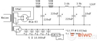
↑ Briefly about the power supply
A TAN-1 127/220-50 power transformer was used. The anode voltage was obtained using a doubling circuit and has no characteristic features. The filament voltage is stabilized, from which the reed switches and indication circuits of the switched on signal source are powered, as well as the high voltage switch-on delay circuit (approximately 40 seconds), assembled on an adjustable zener diode SR1, transistor T2, relay RL1 (RES-48 passport RS 4.590. 204.6 Volts, 42 ohms) and timing elements R5C9. For normal operation of the delay circuit, capacitor C9 must have a low leakage current; here it is made up of two Soviet-made tantalum electrolytes connected in parallel. Diode D13 is a discharge diode, allowing you to quickly restore the functionality of the delay circuit after turning off the power.
Instead of the commonly used method of supplying a “raising” potential to the filament circuit of lamps from a resistive voltage divider (to protect against filament-cathode breakdown and eliminate background), the method often used abroad is used to connect the filament bus after the stabilizer to ground, through a high-voltage capacitor C11.
The windings of the power transformer are connected accordingly to obtain the required voltages and currents. In the standard TAN-1, two filament windings of 6.3 volts are connected in parallel (which is somewhat small, but what can you do); to obtain the operating filament voltage (6.1 V), a transistor (KT819) with a low collector-emitter saturation voltage and current gain is used h21e about 80. On the board it is installed on a small radiator, for which there are mounting holes.
↑ Input selector
You can use almost any input selector switch, for example, a biscuit one.
It does not affect the passage of the audio signal, but only switches the corresponding reed switch coils and the circuits indicating the inclusion of the selected source. I had at hand some kind of 2-section imported biscuit with 5 positions, since the number of inputs is four, the 5th pairs of contacts are not used. The indicator LEDs are blue, 3 mm in diameter and fit well into the “interior”. Almost any LEDs can work in their place, including incandescent light bulbs, depending on what you like.
Amplifier specifications:
Bandwidth (at 1dB ripple) 10 Hz - 100 kHz Bandwidth (at 0.1dB ripple) 20 Hz - 50 kHz Active equalization (see description) + 3 dB at 50 Hz Rise time <2 µs Distortion <0.1% at 1 V signal amplitude in a 100 Hz bandwidth - 10 kHz (at a frequency of 1 kHz typical value is 0.03%) Maximum output signal ~ 30 V at distortion up to 2% (THD) Feedback depth - 18 dB Signal-to-noise ratio > 90 dB Input impedance 50 kOhm Output impedance of the amplifier itself - 5 kOhm Output impedance of the circuit - 100K potentiometer with logarithmic characteristic Channel separation > 50 dB Inputs - RCA Power supply: 6V - 400 mA / 320 V DC - 7 mA Dimensions 135 x 100 x 30 mm
Due to its fairly compact dimensions, the unit can be built into the chassis of a finished amplifier or used as a stand-alone device (with an external power supply).
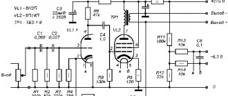
Figure 1 shows the operating principle of the gain stage.
Part of the output signal is fed back to the input, in antiphase, to tightly control the circuit gain. Thus, 18 dB of negative feedback reduces overall gain from +34 dB to +16 dB while reducing the stage's inherent distortion. Due to the reduced influence of the RC feedback circuit (C11, R31) at low frequencies, the circuit gain increases in this range. At the specified values of 220 kOhm and 3.3 nF, a gain increase of 3 dB is provided for frequencies below 100 Hz (see below in the text)
The preamplifier is implemented on a 6Zh32P pentode , which was developed specifically for use in the input stages of tape recorders and is characterized by a low microphone effect and high linearity.
The lamp characteristic has excellent linearity at a bias voltage of -3 V, and an anode voltage of 50 V DC, the voltage on the second grid is 180 V, on the third - 0 V (characteristic highlighted in red):
(Click to enlarge)
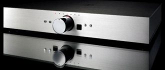
↑ Design
The design of the case was ordered from one of the factories and consists of 7 parts (not counting the decorative overlay on the front panel), made by laser cutting.
Parts are made of sheet steel with a thickness of 2 mm (front and rear panels) and 1.5 mm for all others, followed by painting in matte black. The decorative overlay is made of stainless steel, 1 mm thick. Everyone has the right to come up with their own model and bring it to life. It will probably work out cheaper.
The “brick” turned out to look like a bookcase - the top, bottom and two side covers, the middle panel, which performs the main load-bearing load, are screwed together into a single block along with the front and rear panels.
The volume control and tone control (highlighted in the diagram with a dotted line) are located on a separate single-sided printed circuit board:
installed vertically on 2 10 mm racks -
from the back of the front panel:
The variable resistors themselves are designed for printed circuit mounting -
They are installed on one side of the printed circuit board, all other elements on the other.
Switching board with reed switches:
located on the rear wall, near the input RCA connectors, also on 2 10 mm racks used for mounting printed circuit boards. The board is double-sided, on one side there are printed tracks, on the other there is a screen with countersunk holes for the legs. The reed switches themselves are with two groups of contacts, of Chinese origin (where would we be without them), as already mentioned, type TRR-2A-05-D-00 in a DIP housing.
Silicon low-power diodes that dampen self-induction are attached by soldering directly to the corresponding legs of the reed switches. Both boards are covered on top with a screen also made of foil fiberglass. All of them are connected to the zero bus.
The power supply is also assembled on a printed circuit board installed vertically on the middle shelf using an aluminum angle, and a TAN-1 127/220-50 power transformer is mounted under it.
A standard power socket with a fuse inside is installed at the bottom of the rear wall. The lamps themselves are also placed on the middle shelf and all the corresponding “piping” is mounted in bulk on the lamp panels and auxiliary mounting petals located next to them.
The anode power and lamp filament connections are made with twisted copper pairs of category 5 single-core wires with a diameter of 0.53 mm, which are used to lay computer networks. Their length should be minimal according to the resulting design.
The shielded cable connecting the switch output to the volume control input is of high quality FURUTECH brand. The connection of the RG and PT signal circuits from printed circuit boards to the input lamps is made with shielded wires used for the installation of CLARION audio equipment. Their length should also be as minimal as possible.
Attempt at miniaturization
The given options for powering the filament and anode are quite cumbersome: as many as two network adapters. Is it possible to make it smaller? After all, we live in the 21st century. I will give you options, including unsuccessful ones, so that no one repeats my mistakes.
I’ll say right away that the option of powering the anode with a reduced voltage is not being considered in principle. Somewhere on the Internet I saw a tube overdrive with a 9 Volt power supply - in the sample shown there the sound is extremely disgusting. Also, my own experience in implementing a preamp on a wedge with reduced power produced a sound that left much to be desired. Therefore, we consider only full-fledged high-voltage power supply.
Specialized high-voltage dc-dc converters
1.
There are 300 Volt integrated converters, but they are expensive. For example, a DC-DC converter from Traco Power MHV 12-300 S10 P costs about $200 per case. This is not very good for amateur radio practice, so we will not consider it further.
2.
Ready-made dc-ac converter 12-220 Volts from Aliexpress. Like this:
It's cheap. At idle it consumes about 200 milliamps. At the output there is a diode bridge, when connecting an external capacitor to which we have about 300 Volts. The dimensions allow it to be completely integrated into at least a preamp board:
But alas, during operation it causes such interference that the signal at the anode of the lamp becomes overgrown with a high-frequency “beard”.
3.
Aimtec integrated converters.
Aimtec's commercially available integrated dc-dc converters are relatively inexpensive, small in size and do not cause interference. But they are not high voltage. The highest voltage they output is +/- 24 volts. However, +/-24 volts is 48 volts at the extreme terminals - almost 50. We connect several converters in series, dial the desired value.
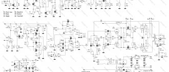
It works. Below is a circuit diagram for a 300 volt converter. We immediately have both a galvanically isolated filament and anode power supply.
No interference was found; you can install it on at least one board with a lamp.
↑ View of the layout
All the insides are visible in the photo:
I don’t think any special comments are needed here. The neutral core is made of 1.5 mm copper wire and is connected to the housing at one point on the rear wall of the block. Power filter capacitors C3, C4, C13 and C14 are mounted directly on the petals of the mounting panels near the lamps. All controls are located outside, at the very bottom there is a power switch, a little higher there is a 4-position flip switch for controlling the switching of reed switches and an input selector indicator, 4 blue indicator LEDs, then separate volume controls and bass and treble controls.
Pre-microphone amplifier based on 4558 chip
The 4558 operational amplifier is manufactured by ROHM. It is characterized as a low power and low noise amplifier. This microcircuit is used in a microphone amplifier, audio amplifiers, active filters, and voltage-controlled generators. The 4558 chip has internal phase compensation, increased input voltage threshold, high gain and low noise. This op amp also has short circuit protection.
Chip 4558 - characteristics
(140.5 KiB, downloads: 3,999)
microphone preamplifier for 4558
This is a good option for building a microphone preamp on a chip. The microphone preamplifier circuit is characterized by high amplification quality, simplicity and does not require much wiring. This dynamic microphone amplifier also works well with electret microphones.
With error-free assembly, the circuit does not require configuration and starts working immediately. The highest current consumption is 9 mA, and at rest the current consumption is around 3 mA.
↑ Selection of parts
The design does not contain any super audiophile parts, all resistors are MLT type, designed for the appropriate power, film capacitors, types K73-9, K73-11, K73-17, also for the appropriate voltage.
Electrolytes made in Taiwan are similar to our K50-35 for a voltage of 400 V. You can use almost any transistors in the power supply that match the parameters indicated in the diagram; their choice is not critical. Diodes in the anode supply - any fast 600 V and a current of at least 1 A, and in a filament rectifier - you can use any diode assembly with a current of at least 3 A and a voltage of 50 V. The 0.5 mH inductor is from an old German telephone, you can install any other one or replace it with a resistor of a hundred Ohms (1 watt).
The TAN-1 power transformer was also chosen because it ended up in old storage. It is attached to the middle shelf through a rubber mat and operates quietly, without buzzing.
To eliminate unnecessary vibrations and microphone effects, four rubber feet from an old phone are glued to the bottom of the unit using 3M double-sided automotive tape.
Amplifier PCB
The board has a small size of 65 x 85 mm and includes a voltage multiplier and a tube preamplifier itself. We connect the voltage from the transformer to terminals 1-2 of the CON1 connector, and a filament current reduction resistor to terminals 3-4. Since this resistor must have a lot of power (3-5 W, depending on what voltage needs to be reduced) and get very hot during operation, it is worth placing it in a place where it will cool better.
The D6 LED is used to indicate the operation of the preamp and can be placed anywhere visible. Resistor R9 sets the brightness. Approximate value 5-10 kOhm. Such a large value is explained by the fact that the diode is supplied with a voltage from a 12-18 V transformer. All resistors, except R10, have a power of 0.25 W.
Diodes D1-D5 - any rectifier for voltages above 100 V. When soldering, pay attention to the correct direction of connecting the diode, as shown on the board. The same should be done when soldering electrolytic capacitors - pay attention to the polarity.
The signal cables for the preamp input and output must be shielded, and the shield must be soldered to ground. Tube amplifiers, due to their high input impedance, are especially sensitive to any errors in the supply of ground; they are easily excited.
The power cords from the transformer and the D6 LED wires must be laid in the form of a twisted pair, that is, in the form of twisted wires. This reduces the spread of electromagnetic radiation from these wires.
↑ Results
The results were encouraging.
Considering the limitations of our living spaces, and most importantly, the financial means to purchase (or independently manufacture) good acoustics. This unit quite delicately interferes with the musical material and allows you to significantly revive the sound of inexpensive speakers. In the process of listening to various musical genres on different speakers, in different rooms (apartments), with different amplifiers (both tube and transistor) and signal sources, it was possible to achieve a completely comfortable sound of the entire path, select the level of “meatiness” and “sonority”, - may the professionals forgive me, in accordance with their auditory preferences.
To be fair, it must be said that the created device turned out to be, in general, an extra link when working together with a tube SE UMZCH with a power of 2x7 watts on GU-50 lamps, assembled by the author based on the circuit of the respected MAI, loaded on an excellent, but, unfortunately, discontinued DANTAX Opus acoustics.
When turning it on in the specified sound path, it was not necessary to turn the bass and treble adjustment knobs beyond the middle position, since at high volumes there was a danger of economic damage from the alarmingly shuddering dishes in the sideboard, as well as the health of the eardrums of people in the room.
Sound examples
The original “reference” sound is simply a line recording.
· Line recording
Via lamp:
· Recording via lamp
It feels like the sound has become more transparent and bright. I played transistor amps for many years through such a preamp; Once I plugged it in directly and was amazed - the sound seemed so muddy without a lamp. Having switched to a tube amp, I removed the tube preamp from “combat duty” - there was no effect from its use.
When using several gadgets, plug in this preamp after the semiconductor overdrive - in this case, the sound will become more readable. It also showed good results on the bass: the sound becomes brighter, especially from the bridge pickup; It doesn't interfere with the bass at all.
And now a small attempt at theoretical research.
↑ Files
For homemade amateurs, skilled craftsmen and professionals who have the necessary fleet of machines, I provide drawings of the body design elements. Maybe it will be useful to someone.