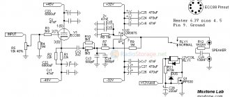
We hope that your home audio system has been updated with a high-quality preamplifier from our latest publications. Now it's time to think about a power amplifier. Today we offer you a description of the design of one very interesting hybrid amplifier . The author Wim de Haene called his creation “MuGen”. In Japanese this means infinity, but from a technical point of view, the amplifier combines a voltage amplifier - Mu and a current amplifier - Gen, which is reflected in the name.
Today, tube amplifiers are undergoing a rebirth - a fairly large number of both commercial and home-made designs have appeared. Unfortunately, their most worthy examples are distinguished by a very immodest price, which is due, in particular, to the need for high voltage to operate the amplifier and the presence of an output transformer . The rather high internal resistance of the lamps does not allow connecting acoustic systems to them directly. And a cheap output transformer of mediocre quality will negate all efforts to assemble the amplifier, no matter how expensive and high-quality the other components are, no matter how well-designed the circuit is.
In hybrid amplifiers, the output transformer is replaced by a transistor stage , which has a low output impedance, which allows you to connect a load to the amplifier output without any tricks. Modern electronic devices make it possible to obtain very high performance and low distortion.
MuGen amplifier parameters and circuit:
- Input sensitivity: 825 mV (8 ohms) and 770 mV (4 ohms)
- Input impedance: 300 kOhm
- Gain: 29 dB (23 dB with overall negative feedback)
- Output power (at 1% THD): 70 W into 8 ohms,
- 110 W into 4 Ohm load
- at 1W/8ohm output power: <0.1%
The amplifier circuit is shown in the figure:
Click to enlarge
Input stage.
To obtain a given output power, the input stage must provide amplification of the input signal to an amplitude of 25V. In addition, due to the absence of general negative feedback, this stage should have minimal distortion when operating at a load of 10 kOhm (input impedance of the output driver).
Based on his experience working with tubes, the author chose a differential stage for the input part of the amplifier, which, among other things, allows it to be used as a bass reflex and it is quite easy to introduce general negative feedback into the amplifier if such a need or desire to experiment arises. In this case, the OOOS signal is supplied separately from the input signal to the grid of the right triode.
Since the cathodes of the lamps of the first AC stage are connected in series, this generates local feedback with a depth of about 6 dB, which reduces the distortion of the stage, but also reduces its gain. Therefore, a high gain lamp is required here. The author chose the ECC83 lamp (analogous to 6N2P).
The current source in the cathode circuit is made active, using transistors, which also significantly improves the parameters of the cascade and makes it possible to implement differential current regulation using simple methods. cascade. The final gain of the first stage is 29 dB.
To enable general feedback in the amplifier, you must close jumper JP1. This will reduce the overall gain to 23 dB, but this is still enough to achieve the specified output power.
Let me remind you that deep overall OOS improves the parameters of the amplifier, but as tests show, it worsens its subjective sound. A feedback depth of -6dB is a good compromise in this case.
The disadvantage of using ECC83 tubes in the input stage is their high output impedance - about 50 kOhm. Coordination with the low-impedance transistor part is provided by a cathode follower on an ECC89 lamp (analogous to 6N23P) with an output resistance of about 500 Ohms.
After much experimentation, the author chose a mode that provided the least distortion and made it possible to match both tube stages directly, without an isolating capacitor. In addition, this ensures a smooth increase in voltage (from 0 to 194 V) on the cathode resistor R7 when the amplifier is turned on, due to which capacitors C2 and C3 are smoothly charged, which eliminates clicks and negative effects on the transistor part.
For many years, power amplifiers used only vacuum tubes, but today modern amplifiers use transistors almost entirely. Tube amplifiers operate on the same principles as transistor amplifiers, but the internal design may be significantly different. In general, tube devices operate at high supply voltage and low current. Unlike transistors which operate at low voltage but with high currents. Additionally, tube amplifiers tend to dissipate a large amount of energy as heat and are generally not very efficient.
One of the most striking differences between tube and transistor amplifiers is the presence of an output transformer in a tube amplifier. Due to the high output impedance of the anode circuit, a transformer is usually required to properly transfer power to the loudspeaker. High-quality audio output transformers are not only difficult to make, but they tend to be large, heavy, and expensive. On the other hand, a transistor amplifier does not require an output transformer, and therefore tends to be more efficient. Many people believe that the sound from tube amps can be excellent and have a unique character. What is certain is that there are sonic differences between tube and transistor amplifiers. I truly appreciate both worlds, and have had the opportunity to hear amazing systems using both technologies.
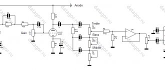
Figure 1: Simplified hybrid amplifier circuit
When developing this hybrid amplifier (Fig. 1), there was a desire to combine the best of tube and transistor technologies. The tubes offer full and faithful sound reproduction, with rich detail, brilliant clarity, and precision. They also reproduce deep better. The hybrid amplifier retains the signature of a tube amplifier, complementing it with a low-distortion solid-state output stage.
Figure 2: Hybrid Amplifier Circuit
The hybrid amplifier circuit (Figure 2) is very simple, but includes interesting ideas such as Erno Borbely's low-voltage tubes and Reinhard Hoffmann's bipolar-supplied output stage. This hybrid is capable of delivering about 30W into an 8Ω load or 15W into a 4Ω load. You can easily increase the power by adding more output stages in parallel. This will increase the damping coefficient and reduce the dependence on load resistance. An amplifier with two MOSFET output transistors per channel will provide more than 50 +50 W of pure Class A usable power into loads up to 6-8Ω. However, in such conditions the amplifier will dissipate more than 300 W, so you must use suitable heatsinks (at least 0.2 °C/W thermal resistance) in a suitable well-ventilated case.
Figure 3. Power supply circuit
The input stage is based on a double triode 6DJ8/ECC88 (analogous to 6N23P, you can also try 6N6P) and serves as a differential amplifier. I chose the 6DJ8 because of its linearity and good performance at 35-40V anode voltage. For 6DJ8/6922/ECC88/E88CC, MU is constant within 20% of 0.4mA, up to at least 6mA, and this trend continues up to 15mA. I chose an operating current of 3-5 mA for each half of the lamp, and a voltage of 35-40V to keep dissipation well below the nominal value of 1.8 W. The cathode receives current from a constant current source at Q3, while Q1 and Q2 represent a resistive load or current mirror. The active anode/cathode load of both triodes is almost equal, which reduces the second harmonic, promotes linearity and increases the slew rate of the output voltage. With potentiometer P3, you can adjust the bias current from 1 to about 7mA, P1 controls the output bias voltage, which needs to be adjusted close to 0.
OUTPUT CASCADE
Output stage consisting of one or more single-ended, Class A P-channel MOSFETs, similar in configuration to Nelson Pass's Zen amplifier (for more details, see https://www.passlabs.com/
zenamp.htm). It is loaded onto current source Q4, which is set to 3A quiescent current using the specified values of R14. You can experiment with different values of the quiescent current by changing the resistance R14 using the formula Id = (Vz-Vgs)/R14 =0.9/R14.
It should be taken into account that the quiescent current should be 50% greater than the operating current. The overall gain of the amplifier is around 20 and this depends on the value of R8 and R9. Thus, 1V of the input signal will drive the amplifier to full power, so that the output level of a typical CD player is sufficient to drive the amplifier. You can calculate the required gain using the following formula: Av = 1 + (R9/R8). This amplifier's tested PCB is available in Ivex Win-Board format. To receive a free copy of the file, please send an email In this PCB, the tubes and transistors are mounted on the solder side.
Each channel of the hybrid amplifier requires ±35V DC/6A power supply for the main amplifier, and an adjustable 6.3V DC/0.5A for powering the filament lamps. The rectifiers of the amplifier's main power supply must withstand 20A.
RESULTS
This hybrid amplifier has a flat frequency response across the entire audio frequency range. Even with low-sensitivity speakers, you can appreciate its clarity and detail, especially when the CD player is directly connected to it. With a single output, the amplifier delivers up to 20W with less than 1% THD, but it will perform better with two in parallel. I've had the opportunity to evaluate some of the best Class A amplifiers on the market, and I believe this hybrid delivers the same flavor and fresh feeling when listening to high-end music.
1. “Low-Voltage Tube/MOSFET Line Amp,” GA 1/98.
2. “The Zen Cousins,” AE 4/98.
audioXpress 5/01
www.audioXpress.com
Corrected amplifier circuit.
I greet all visitors to the site and present the design of the UMZCH, which in my opinion (ear) is the embodiment of all the best that we can take from modern transistors and vintage lamps.
Power: 140 W Sensitivity: 1.2 V
The circuit contains a small number of parts, is easy to configure, does not contain scarce or expensive components, and is very thermally stable.
Briefly about the scheme.
The source follower is implemented on complementary MOSFET transistors IRFP140, IRFP9140 and has no special features. Transistor VT1 does not affect the sound; it is needed to stabilize the current when the temperature of the output transistors changes and is installed in close proximity to them on the cooling radiator. It is advisable to have a massive radiator with a large cooling area; install the transistors close to each other on a heat-conducting paste, through a mica gasket. Capacitor C4 provides a “soft” start for the source follower.
Now about the driver.
I had to tinker with the driver, because... input capacitance of one transistor is 1700 pf. Different types of lamps and different switching schemes were tested. We had to abandon low-current lamps because... The HF blockage began already in the audio range. The result of the search was SRPP on 6N6P. When the current of each triode is 30 mA, the amplifier’s frequency response extends from a few hertz to 100 kHz, a smooth decline begins around 70 kHz. The 6N6P lamp is very linear, and the 6N6P driver has a huge overload capacity. Modes of triodes 6N6P - 150V, 30mA. According to the datasheet Pmax -4.8W, we have 4.5, almost at the limit. If you feel sorry for 6N6P, you can make the regime easier by increasing the values of resistors R3 and R4, say to 120 Ohm. And yet, despite the fact that the 6N6P lamp has a small gain, it turned out to be prone to self-excitation, maybe it’s all due to the copies I have, but, nevertheless, measures were taken to suppress this undesirable phenomenon. A standard aluminum screen was put on the lamp, the ninth leg was sealed to the ground, a small coil was installed in the grid - 15 turns of PEV 0.3 wire wound around a 150 kOhm - 1 W resistor. If an even frequency response at HF is not the main thing for you, you can try it in the 6N8S or 6N23P driver, in the SRPP, of course. Setting up the amplifier is simple - set R5 to the middle position, and R8 to the lowest position according to the diagram and turn on the amplifier. Warm up for 3 minutes, turn R5 - set “0” at the output, then carefully turn R8 - set the quiescent current of the output transistors. We control the current by measuring the voltage drop; at any of R15, R16 it should be 110mV, which corresponds to a current through the output transistors of 330mA. The quiescent current is at your discretion - it all depends on the radiators and fans at your disposal. The amplifier setup is complete - enjoy the sound. I don’t include the power supply, because... everyone can develop it themselves. But I want to warn you that saving on a power supply is the last thing. Install large transformers, huge containers and you will be rewarded. Don't forget to install fuses everywhere.
Details
. The parts are the most common, OMLT resistors, JAMICON capacitors, resistors R15, R16 are made up of three parallel-connected OMLT-2 - 1 Ohm, R8 - wirewound, ALPS input potentiometer. The use of audiophile components is encouraged, this especially applies to the power supply capacitors. Separately, it is necessary to say about C3, C4, C5, the sound of the amplifier depends on them, so it is better for you to choose the type of capacitors to suit your taste. I have imported red-brown film films from an unknown manufacturer, I suspect they were made in the Middle Kingdom. If you do not need the amplifier’s frequency response to be linear from 2Hz, then the capacitances of capacitors C3 and C5 can be reduced. It is advisable to select the output transistors in pairs according to their parameters. When the amplifier is turned on, an alternating current background is heard for several tens of seconds, then it disappears. This phenomenon is due to the fact that the source follower has a high input resistance and while the cathodes of the triodes are warming up, the follower input is “suspended” and “receives” the electromagnetic fields surrounding it at the frequency of the industrial power supply network. There is no need to fight this phenomenon - you need to implement a delay in turning on the speakers. Amplifier power – 140 W, at Uin.eff. – 1.2V. There is nothing to measure the coefficient of nonlinear distortion, but I don’t think that this amplifier has it, judging by the sound.
Now about the sound itself.
The sound of this amplifier is similar to the sound of a triode push-pull, but the bass register is much meatier, the bass is fast, clear and solid. The middle is transparent and detailed, the highs are without the “sand” inherent in transistors. The amplifier eats everything, pumps any acoustics. The amplifier was conceived for use outdoors - at home it is a single-ended tube, but now I am not sure that it will not be the main one. Let's listen again.
And yet, when building an amplifier, it is advisable to equip it with a system of all kinds of protection; this will improve its performance and protect your speaker from emergency situations.
List of radioelements
| Designation | Type | Denomination | Quantity | Note | Shop | My notepad |
| VT1 | Bipolar transistor | KT602BM | 1 | To notepad | ||
| VT2 | MOSFET transistor | IRFP140 | 1 | To notepad | ||
| VT3 | MOSFET transistor | IRFP9140 | 1 | To notepad | ||
| Diode | KD521A | 2 | To notepad | |||
| Zener diode | 12 - 15V | 2 | To notepad | |||
| Lamp | 6N6P | 2 | To notepad | |||
| C1 | Electrolytic capacitor | 10000uF x 50V | 1 | To notepad | ||
| C2 | Capacitor | 0.1uF x 63V | 1 | Film | To notepad | |
| C3-C5 | Capacitor | 6.8uF x 63V | 3 | Film | To notepad | |
| R1 | Variable resistor | 50 kOhm | 1 | To notepad | ||
| R2 | Resistor | 220 kOhm | 1 | 1W | To notepad | |
| R3, R4 | Resistor | 100 Ohm | 2 | 2W | To notepad | |
| R5 | Trimmer resistor | 33 kOhm | 1 | To notepad | ||
| R6 | Resistor | 86 kOhm | 1 | 1W | To notepad | |
| R7 | Resistor | 56 kOhm | 1 | 1W | To notepad | |
| R8 | Trimmer resistor | 15 kOhm | 1 |
This circuit of a tube-transistor headphone amplifier has been repeated by many lovers of good sound and is known in many versions, both using bipolar transistors at the output and field-effect ones.
Class-A anyway
. It attracts with its simplicity and repeatability, which I was also convinced of, at the same time having a desire to hear the music “performed by him.”
I bring to your attention the concept of building a hybrid single-ended circuit, the development of which was prompted by the articles “Pocket Ugly Duckling, or Pockemon-I” by Oleg Chernyshev and “Tube-semiconductor ULF” (zh. Radio No. 10 for 1997).
The first article describes a tube amplifier whose output stage is covered by a parallel negative feedback (NFE) circuit. The author complains about possible criticism for the lack of modernity of such a circuit solution (OOS and even on the first grid). However, such solutions were widely used during the golden era of tube sound engineering. See, for example, the article “Radiola Ural-52” (zh. Radio No. 11 for 1952).
I like the simplicity of implementing such an OOS: there are only two elements in the feedback circuit, these are resistors and one of them, as a rule, serves as a load for the driver stage. Such OOS does not require adaptation to the type of output lamp used (within reasonable limits). But! In the same article, the author, citing calculation formulas, says that it is necessary, depending on the output resistance of the driver stage, to adjust the values of the feedback circuit resistors. So many “opportunities for creativity”! I installed another lamp and re-soldered a couple of resistors. It seemed wrong to me.
In my article I propose a solution to this “problem”.
They asked me to make an amplifier for sounding a room of 50 m 2, a kind of “village club”. It must be said that there is already some kind of industrial amplifier there, which is used for all kinds of events such as “disco”. That is, it plays loudly, but at the expense of quality. An amplifier was needed specifically for more or less high-quality listening to music, 30 watts per channel.
I couldn’t make a tube amplifier of such power, so I turned my attention to hybrid amplifiers. We have it on Datagor. Let me remind you that “Corsair” is in a fan-powered configuration with a tube buffer at the input. I decided to study reviews and opinions on the Internet.
What remained was a working prototype of the SRPP on 6N23P. It was a shame to throw it away. There was a desire to finish the amplifier to the end. In the previous craft, we had to apply some simplifications related to the size of the case, for example: common power supply for both channels, not exactly the capacities that I would like to try.
It was decided to make a new SRPP headphone amplifier on the 6N23P without these simplifications. The result was suddenly this kind of hybrid.
Greetings, dear Datagorians! I present to your attention a hybrid headphone amplifier based on a 6AQ8 (6N23P) tube and IRF540 field-effect transistors.
Printed circuit board drawings, installation details included, no background.
04/29/14 changed by Datagor. Amplifier circuit corrected
I have long wanted to listen to how a lamp and a stone sound in tandem. I decided to build a hybrid headphone amplifier. I looked at several diagrams. The main criterion for choosing was the simplicity of the circuit, and therefore the ease of its assembly. I settled on two: 1) S. Filin. Tube-transistor amplifier for stereo phones. 2) M. Shushnov. Hybrid headphone amplifier. (Radiomaster No. 11 2006) In general, these schemes are not much different from each other and without major changes you can try both one and the other. I decided to put together a diagram of M. Shushnov with field workers.
Another failed experiment led to the idea of a lamp buffer for and it turned out when I conscientiously filtered the power supply to the lamps.
It took me a long time to come up with the idea of a tube buffer, but all the failures are in the past and the idea justified itself. Not only op-amps can match resistances - a cathode follower on a suitable lamp is also suitable for this purpose.
The plane was confidently descending along the glide path, as if following an invisible thread; the runway was quickly approaching. The turbines smoothly switched to idle, the plane hovered over the runway and a second later rolled, counting the joints between the concrete slabs. The reverse flaps shifted, and the silence was cut by the sound of air being turned away by the flaps...
Alas, I heard it many times, but the reproduced sound of reverse by the flight simulator through Genius tweeters did not impress me. And listening to music without headphones did not bring any pleasure. And then I decided it was time to get decent acoustics for my computer. Without thinking twice, I wrote a message to Sergei (SGL) asking what I could buy that would please my ears. To which I received the answer, the best speaker is a self-made speaker! Let's say. And then I received a link from him. That's how I ended up on Datagor.
Sorry about the photo, I only have a multimedia camera.
Few people have tubes left, but they can still be purchased, so tube audio equipment is of constant interest to radio amateurs. You give us that same warm tube sound that has long become a meme that people like to put into place and not so much. Now let's try to combine old tube audio equipment with a more modern element base. You can get simply magical sound.
The amplifier is assembled according to a classic single-ended circuit. During the setup process, I changed some resistor values. So it was necessary to select R23, R34 so that the voltage at the anodes of the 6p14p lamp was 190V. Then, by selecting R45, we set the anode voltage on the 6n3p lamp 90-110V.
I used a BA3822LS circuit as a tone block. This microcircuit has good technical parameters and is not expensive. The main advantage of its use is the absence of a huge number of shielded wires and screens; in the absence of a signal, background noise was not heard. Connect the assembled tone block to the input of the tube ULF through 100k tuning resistors.
When making the power supply, I used a ready-made TS270 transformer and added a little more turns on top of the windings.
One rectifier is used in both channels. The output transformers are completely homemade, type TS-20.
We wind them as follows: the primary winding contains 94 turns of 0.47 wire and 900 turns of 0.18 wire; in short, in the end it should be 94/900/94/900/94/. We connect the primary winding in series, the secondary in parallel.
For the body I took sheets of three millimeter aluminum. I took the adjustment knobs from aluminum furniture handles, drilled holes to the required diameter and put them through heat shrink directly onto the variable resistors.
The power supply for the lamp stage is supplied from an unstabilized source of 300…350 volts. The filament voltage of 6.3 V does not need to be rectified or stabilized. The filament lamps of the right and left channels of the amplifier can be connected to one winding of the transformer, but it is recommended to make the anode circuits separate.
The amplifier passed the hearing test excellently - crystal clear sound, especially in the middle and top of the sound range.
The input amplifier is made using a pair of 2SK68A field-effect transistors and high-voltage bipolar 2SC1941 transistors, forming a cascade that acts as a phase inverter for the output push-pull stage on the EL34 in triode connection. This hybrid power amplifier circuit using field-effect transistors and tubes is a very high-quality sound reinforcement equipment of the highest class, so installation and soldering must be done as carefully and carefully as possible.
Static balancing of the amplifier is carried out with a 5 kOhm trimmer in the circuit for supplying a fixed bias to the control grids, and dynamic balancing with a 2-kOhm trimmer in the power supply circuit for the collectors of bipolar transistors. Despite the fact that the circuit contains transistors, the amplifier is made without OOS and has a clear “tube” sound.
| Hybrid UMZCH 70 W |
This hybrid UMZF provides full power bandwidth from 30 Hz to 100 kHz and small-signal frequency response from 10 Hz to 170 kHz. The function of a voltage amplifier and phase inverter is performed by a cascade based on composite transistors Q1Q3, Q2Q4 with a current generator Q8 in the emitter circuits and an improved current mirror Q5Q6Q7 in the collector circuits.
The fixed bias on the control grids of the radio tubes is adjusted using resistor R15 so that the initial anode currents are about 40 mA. The output toroidal transformer VDV3070PP Amplimo was purchased at an online auction. Its primary winding has a resistance of 2757 Ohms, its rated power is 70 W
This hybrid amplifier circuit delivers 80 W of power into eight ohms with 0.04% THD, 5 Hz - 35 kHz bandwidth (20 W, -3 dB) and has a signal-to-noise ratio of over 100 dB.
The only voltage amplification stage in the circuit is built on a 2SC2547E bipolar transistor with a dynamic load on an ECC88 triode.
The output stage is designed as a push-pull source follower based on a complementary pair of powerful field-effect transistors IRF640, IRF9640. Their operating point is set by trimmer PR1 during adjustment.
Capacitor C2 and resistor R9 are used to form a voltage addition circuit familiar to transistor amplifiers. In this circuit, it helps radio tube V1 to ensure normal swing of the output stage at a relatively low anode voltage.
The audio signal, through the volume control on resistor R1, enters the VL1.1 triode (control grid) of the amplifier and is amplified. The negative bias potential slightly blocks the triode formed on its control grid with the help of the anode current, which passes through resistors R3 and R4 located in the cathode circuit. The voltage will drop across these resistances, therefore, relative to the negative bus, a positive voltage of approximately +1.7V will be present at the cathode of the lamp.
On the control grid of the amplifier tube, if compared with the cathode, there will be a negative bias potential, since the grid has a common contact through resistor R1 with ground. To reduce the effect of feedback in the tube amplifier circuit there is a resistance R3, which is shunted by the electrolytic capacitance C1. Resistor R2 plays an important role as a load for the anode circuit of a tube amplifier. The voltage of the amplified audio signal generated on it is supplied through the isolation capacitor C2 to the control grid of the lamp pentode. Through the first output transformer, the signal amplified by it goes to the amplifier's loudspeaker.
Resistor R8 and capacitor C7 perform the same function as similar elements in the first stage. C6 and R6 are designed to change the timbre of the sound. Using resistor R9, a second negative feedback circuit is obtained. By capturing both stages of a tube amplifier, it reduces nonlinear distortion and creates the smoothest amplification of the audio signal across the entire audio frequency range.
The second transformer of the tube amplifier is wound on a magnetic core with a cross-section of 10 cm (W22 x 40). The primary winding is PEV-1 wire 0.2-0.25 mm 1040 turns. The secondary winding has 965 turns of the same wire, the third has 34 turns wound with PEV-1 wire 0.6-0.8 mm.
The first transformer of the TVZ21 type. It is allowed to use any output transformer from a tube TV.
Isolation capacitors.
The voltage amplification stage (tube part) and the current amplification stage (transistor part) are interconnected through isolation capacitors. The circuit cannot do without this, because the voltage at the cathode of the ECC88 lamp is about 194 V. Unfortunately, these capacitors significantly affect the sound of the amplifier.
After conducting listening tests on this amplifier, the author chose the ClarityCap SA series capacitors, which have a very good price/quality ratio. Due to its high operating voltage (600 V), the SA series is very well suited for use in tube circuits.
The topology of the printed circuit board allows the design to use high-quality capacitors from other manufacturers, including Wima and Solen . The value of 3.3 µF was chosen to ensure a roll-off of the frequency response below 10 Hz. The isolation capacitor, together with the input resistance of the transistor stage, constitutes a filter, the cutoff frequency of which can be determined by the formula:
1 / (2π* 3.3 µF * 10 kOm)
The operating voltage of the coupling capacitors must be at least 400V.
Output stage.
The output stage of the amplifier is built on bipolar transistors . Of course, it would be possible to use MOSFETs such as BUZ900P or 2SK1058, but the author deliberately eliminated them. The selected transistors are quite often used in audio amplifiers and, with very good characteristics for audio applications, they have a very modest price and high reliability.
The output stage is quasi-complementary, i.e. built on transistors of the same conductivity in both arms. This configuration was widespread in the 70s and 80s due to the lack of available pnp complementary transistors. And, in general... it has earned a bad reputation. But! The author believes that in principle there are no completely complementary transistors, and therefore, using transistors of the same type, it is possible to achieve greater actual symmetry of the cascade arms. The well-known company Naim uses only this output stage configuration in its amplifiers.
The supply voltage is 38 V, which is optimal for this output stage and allows the amplifier to be operated without problems for a 4-ohm or 8-ohm load.
All over your head
The NTA-25V model is designed not only to work with speaker systems, but is also positioned as a self-sufficient headphone amplifier. Let's start with them. The manufacturer promises reliable playback with headphones with an impedance of 32–320 Ohm, so for the test I chose closed Beyerdynamic DT 250/250 Ohm monitors.
Connecting to the “musical” smartphone LG V20 via Bluetooth turned out to be quick and easy: you just had to turn the round knob on the front panel to the “VT” indicator and point in the phone menu to the inscription “NTA-25V” that appeared.
Developer mode showed that Android automatically selected the aptX codec, and I must admit that in this case it is not immediately possible to notice the difference between an over-the-air connection and a cable connection through the phone's 3.5 mm audio jack - even if you enable DSD digitization of the sacred Pink vinyl Floyd "Wish You Were Here".
The preamplifier section uses two pairs of Chinese tubes 6P1 and 6N1
Of course, it is expected that the upper frequencies on the “blue tooth” sound a little more simplified, a little duller and there are fewer of them - but not so much as to spoil the impression. The lows are not so sharp and defined, but also quite clear and distinguishable.
And most importantly: the stage does not become flat and does not lose volume, as often happens with such a connection. So, despite the fact that in “peaceful life” I basically don’t use Bluetooth sound transmission, this time I unexpectedly listened to the album to the end.
I also found it convenient to control the tracks using the round knob: I turned it left and right - I turned on the previous or next track, I pressed the knob - I paused the track or started it again. It's faster than unlocking your smartphone and sliding your finger across the screen.
The mesh cover protecting the lamps looks quite stylish
Now let's listen to music over the wires. The source was an iMac with the Audirvana Plus software player, which sent a signal to an external DAC via a USB output - in this role I used the compact Chord Mojo, which had previously proven itself worthwhile as a “stationary” in linear mode.
I chose the composition “I Want, I Want” by the St. Petersburg group “Stolen Sun” for its sharp, defined highs and delicate bass guitar, which I still need to try to properly present to the listener. This time, in the HTA-25B interpretation, there were too many highs: they are no longer sharp, but downright unpleasantly piercing.
The situation is similar with the lows: the bass guitar is not just audible - it hums noticeably. But the situation is fixable, you just have to lower the frequencies to taste using the tone control knobs, which until this moment were in a neutral position, and the sound becomes quite pleasant and comfortable.
A toroidal transformer is hidden behind a large opaque casing
It is important to note here that the sound in headphones is highly dependent on the DAC - after all, the “British” is able to bring out even deeply hidden details and nuances of the recording, presenting them brightly and prominently, but its own amplifier handles them extremely carefully, while the HTA-25B , having received a signal in linear mode, enhances its advantages and disadvantages as if under a magnifying glass.
However, as soon as I connected the LG V20 smartphone with QuadDAC based on the ESS Saber S9218 with its emphatically smooth and even presentation, the highs tidied up by themselves, the low frequencies became less (the hum, however, did not completely disappear), but the mids also seemed slightly muffled. So the Korean “audiophone” paired with TAGA Harmony turned out to have a deliberately “sleek” sound.
But chamber classics - in particular, the impeccably recorded album “JS Bach. Oboenwerke. Alexei Utkin. Hermitage Chamber Orchestra" - performed by the tandem of Mojo and HTA-25B, it sounded very good and without any exercises with the tone controls.
But the nuances of presentation are also felt here: if the “British” himself emphasized virtuosity and musicality, then in the duet these qualities gave way somewhat to emotionality and expressiveness. That is, the sound of instruments - especially strings (mainly cello) - has lost a little in detail, but has become brighter and more distinct.
But where the TAGA Harmony HTA-25B worked great with headphones is when playing digital recordings from vinyl of the 70s. That very moment when the “good old” becomes “warm and luminous.”
The legendary guitar solo in Deep Purple’s “Highway Star” sounded much more rich, voluminous and emotional compared to Mojo’s smooth and “correct” delivery in the solo version. The same can be said about Murray Head’s vocals in the part of Judas (composition “Heaven on Their Minds” by Jesus Christ Superstar), which added more expression and expressiveness.
Here you can argue for a long time about “even tube harmonics” and their real influence on the perception of sound, but old recordings that have not been remastered really take on a pleasant and comfortable coloring, if you like - a kind of “pseudo-authenticity”. Whether this is good or not is a matter of personal taste, but this curious nuance is worth paying attention to.
Looking ahead, I will say that it is with headphones, and not with speakers, that the HTA-25B amplifier is able to best convey the nuances of recordings and the peculiarities of the presentation of sources.
Learn more about schema elements.
Resistor R1 is the grid resistor of lamp V1a. Its value is not critical, but its presence is required! Resistor R2, together with the input capacitance of the lamp, forms a low-pass filter to protect the amplifier input from interference. A similar role is played by resistor R5 for the cathode follower.
The values of resistors R3 and R4 were chosen to obtain a voltage slightly more than 190V at the anodes of the lamps. In this case, the current through each lamp is 0.8 mA. Current source for differential The cascade is built on transistors Q6, Q7 to increase its internal resistance. The LED sets the reference voltage, and trimmer P1 can be used to conveniently and accurately set the required source current. To power the current generator, a stabilizer on the LM337 chip is used.
If desired, general negative feedback can be introduced into the circuit. Its depth depends on the values of resistors R6 and R8. With the values indicated in the diagram, the OOOS depth is 6 dB. To increase stability, you can connect a small capacitor (56 pkF) in parallel with R8. If you do not like experiments or are an ardent opponent of negative feedback, then elements R6, R8, JP1, Cfb do not need to be installed. Even without overall feedback, this amplifier has very low distortion.
The quiescent current of the cathode follower lamp is selected to be about 9 mA. To reduce distortion and output resistance of the cascade, it is advisable to set this value higher, but this may negatively affect the service life of the lamp. The author made a compromise decision.
Transistor Q1 sets the quiescent current of the transistor output stage. To ensure thermal stabilization, it must be fixed as close as possible to the output transistors on a common heatsink. Resistor P2 must be multi-turn and with reliable contact with the motor.
Resistors R11, R16, P3 determine the input resistance of the transistor part of the amplifier (with the indicated ratings it is about 10 kOhm). When using field-effect transistors, the values of these resistors can be significantly increased. Trimmer P3 is used to adjust “0” at the amplifier output. The author deliberately did not use an integrator for these purposes, as he believes that it negatively affects the sound.
Elements R12/C4 and R20/C8 are additional power filters, and it is highly not recommended to exclude them from the circuit. The capacitances of capacitors C4 and C8 can be in the range of 220 µF-330 µF.
Transistors Q2 and Q4 form a classic composite Darlington transistor , which provides the necessary current gain. Transistors Q3 and Q5 form a compound Sziklai transistor , simulating a complementary PNP transistor. Since Q4 and Q5 are of the same type, in the author’s opinion, complementarity is achieved here more completely. To reduce the distortion of the Sziklai stage, a Baxandall diode is usually added to it. The author replaced it with a diode-connected transistor (indicated Qbax in the diagram), which made it possible to further reduce the distortion of the output stage. The measured distortion at 1 W output power with the diode was 0.22%, and with the 2SC1815 transistor turned on by the diode it was only 0.08%. At higher output power levels, the difference between the diode and transistor decreases. The printed circuit board allows you to install transistors of types 2SC1815 or 2SC2073 or just a 1N4007 diode.
Due to the presence of local negative feedback, the output stage has low distortion and good thermal stability. Resistors R21 and R22 should be non-inductive and as small as possible.
Elements R23 and C7 form a Zobel circuit to ensure amplifier stability at frequencies above 100 kHz. Base resistors R13, R17, R14, and R18 also prevent possible excitation at high frequencies. With a capacitive load of this amplifier, to increase its stability, you can connect an inductance in series with the output (as is often done). The coil contains 16 turns of copper wire with a diameter of 0.75 mm, wound on a mandrel with a diameter of 6.3 mm or on a 15 Ohm resistor with a power of 2 W.
The circuit diagram of the protection device and delay for switching on the speaker systems is shown in the figure:
Click to enlarge
It provides a delay in connecting speakers 30 seconds after turning on the amplifier and turning them off when dangerous DC voltage appears at the output. To minimize the impact on the sound, the relay for this block must be selected with reliable and high-quality contacts.
Hybrid UMZCH without environmental protection
I greet all visitors to the site and present the design of the UMZCH, which in my opinion (ear) is the embodiment of all the best that we can take from modern transistors and vintage lamps.
Power: 140 W Sensitivity: 1.2 V
The circuit contains a small number of parts, is easy to configure, does not contain scarce or expensive components, and is very thermally stable.
Briefly about the scheme. The source follower is implemented on complementary MOSFET transistors IRFP140, IRFP9140 and has no special features. Transistor VT1 does not affect the sound; it is needed to stabilize the current when the temperature of the output transistors changes and is installed in close proximity to them on the cooling radiator. It is advisable to have a massive radiator with a large cooling area; install the transistors close to each other on a heat-conducting paste, through a mica gasket. Capacitor C4 provides a “soft” start for the source follower.
Now about the driver. I had to tinker with the driver, because... input capacitance of one transistor is 1700 pf. Different types of lamps and different switching schemes were tested. We had to abandon low-current lamps because... The HF blockage began already in the audio range. The result of the search was SRPP on 6N6P. When the current of each triode is 30 mA, the amplifier’s frequency response extends from a few hertz to 100 kHz, a smooth decline begins around 70 kHz. The 6N6P lamp is very linear, and the 6N6P driver has a huge overload capacity. Modes of triodes 6N6P - 150V, 30mA. According to the datasheet Pmax -4.8W, we have 4.5, almost at the limit. If you feel sorry for 6N6P, you can make the regime easier by increasing the values of resistors R3 and R4, say to 120 Ohm. And yet, despite the fact that the 6N6P lamp has a small gain, it turned out to be prone to self-excitation, maybe it’s all due to the copies I have, but, nevertheless, measures were taken to suppress this undesirable phenomenon. A standard aluminum screen was put on the lamp, the ninth leg was sealed to the ground, a small coil was installed in the grid - 15 turns of PEV 0.3 wire wound around a 150 kOhm - 1 W resistor. If an even frequency response at HF is not the main thing for you, you can try it in the 6N8S or 6N23P driver, in the SRPP, of course. Setting up the amplifier is simple - set R5 to the middle position, and R8 to the lowest position according to the diagram and turn on the amplifier. Warm up for 3 minutes, turn R5 - set “0” at the output, then carefully turn R8 - set the quiescent current of the output transistors. We control the current by measuring the voltage drop; at any of R15, R16 it should be 110mV, which corresponds to a current through the output transistors of 330mA. The quiescent current is at your discretion - it all depends on the radiators and fans at your disposal. The amplifier setup is complete - enjoy the sound. I don’t include the power supply, because... everyone can develop it themselves. But I want to warn you that saving on a power supply is the last thing. Install large transformers, huge containers and you will be rewarded. Don't forget to install fuses everywhere.
Details . The parts are the most common, OMLT resistors, JAMICON capacitors, resistors R15, R16 are made up of three parallel-connected OMLT-2 - 1 Ohm, R8 - wirewound, ALPS input potentiometer. The use of audiophile components is encouraged, this especially applies to the power supply capacitors. Separately, it is necessary to say about C3, C4, C5, the sound of the amplifier depends on them, so it is better for you to choose the type of capacitors to suit your taste. I have imported red-brown film films from an unknown manufacturer, I suspect they were made in the Middle Kingdom. If you do not need the amplifier’s frequency response to be linear from 2Hz, then the capacitances of capacitors C3 and C5 can be reduced. It is advisable to select the output transistors in pairs according to their parameters. When the amplifier is turned on, an alternating current background is heard for several tens of seconds, then it disappears. This phenomenon is due to the fact that the source follower has a high input resistance and while the cathodes of the triodes are warming up, the follower input is “suspended” and “receives” the electromagnetic fields surrounding it at the frequency of the industrial power supply network. There is no need to fight this phenomenon - you need to implement a delay in turning on the speakers. Amplifier power – 140 W, at Uin.eff. – 1.2V. There is nothing to measure the coefficient of nonlinear distortion, but I don’t think that this amplifier has it, judging by the sound.
Now about the sound itself. The sound of this amplifier is similar to the sound of a triode push-pull, but the bass register is much meatier, the bass is fast, clear and solid. The middle is transparent and detailed, the highs are without the “sand” inherent in transistors. The amplifier eats everything, pumps any acoustics. The amplifier was conceived for use outdoors - at home it is a single-ended tube, but now I am not sure that it will not be the main one. Let's listen again.
And yet, when building an amplifier, it is advisable to equip it with a system of all kinds of protection; this will improve its performance and protect your speaker from emergency situations.
List of radioelements
| Designation | Type | Denomination | Quantity | Note | Shop | My notepad |
| VT1 | Bipolar transistor | KT602BM | 1 | Search in the Otron store | To notepad | |
| VT2 | MOSFET transistor | IRFP140 | 1 | Search in the Otron store | To notepad | |
| VT3 | MOSFET transistor | IRFP9140 | 1 | Search in the Otron store | To notepad | |
| Diode | KD521A | 2 | Search in the Otron store | To notepad | ||
| Zener diode | 12 - 15V | 2 | Search in the Otron store | To notepad | ||
| Lamp | 6N6P | 2 | Search in the Otron store | To notepad | ||
| C1 | Electrolytic capacitor | 10000uF x 50V | 1 | Search in the Otron store | To notepad | |
| C2 | Capacitor | 0.1uF x 63V | 1 | Film | Search in the Otron store | To notepad |
| C3-C5 | Capacitor | 6.8uF x 63V | 3 | Film | Search in the Otron store | To notepad |
| R1 | Variable resistor | 50 kOhm | 1 | Search in the Otron store | To notepad | |
| R2 | Resistor | 220 kOhm | 1 | 1W | Search in the Otron store | To notepad |
| R3, R4 | Resistor | 100 Ohm | 2 | 2W | Search in the Otron store | To notepad |
| R5 | Trimmer resistor | 33 kOhm | 1 | Search in the Otron store | To notepad | |
| R6 | Resistor | 86 kOhm | 1 | 1W | Search in the Otron store | To notepad |
| R7 | Resistor | 56 kOhm | 1 | 1W | Search in the Otron store | To notepad |
| R8 | Trimmer resistor | 15 kOhm | 1 | Search in the Otron store | To notepad | |
| R9 | Resistor | 15 kOhm | 1 | 1W | Search in the Otron store | To notepad |
| R10 | Resistor | 100 kOhm | 1 | 1W | Search in the Otron store | To notepad |
| R11, R12 | Resistor | 10 kOhm | 2 | 1W | Search in the Otron store | To notepad |
| R13, R14 | Resistor | 150 Ohm | 2 | 1W | Search in the Otron store | To notepad |
| R15, R16 | Resistor | 0.33 Ohm | 2 | 5W cement axial | Search in the Otron store | To notepad |
| Add all | ||||||
Attached files:
- amp139.lay6 (151 KB)
Tags:
- ULF
- Sprint-Layout
power unit
The high-voltage part of the circuit is powered by a stabilizer built on the TL783 chip. The input voltage should be about 360V. The microcircuit is installed on a small radiator and is securely isolated from the case. The output voltage of 315V is set by divider resistors R39/R40. Resistor R41 serves to discharge the capacitors after the amplifier is turned off.
R42/C27 and R43/C28 are additional filters for the left and right channels. After them, the output voltage of the power supply is 310V. If you cannot find a Wima FKP1 (see specification), then it is better to exclude it from the circuit!
Click to enlarge
The secondary winding of transformer T1 with a voltage of 30V is used to power the AC protection device (not stabilized).
The filament voltage is connected to the common wire (to reduce the background) through a capacitor . It cannot be directly connected to ground since the voltage at the cathode of the ECC88 lamp is 194V, which is greater than the maximum permissible cathode-grid voltage. A capacitor easily solves this problem. Resistor R36 is selected experimentally so that the filament voltage is ~6.3V.
The output stage of the amplifier is powered by an unstabilized voltage of 38V. All transformers in the author’s design are toroidal.
Design.
All amplifier blocks are assembled on printed circuit boards. Each amplifier channel is assembled on a separate board, so for the stereo version you will need two of them.
The author guarantees that you will get the best results if you use exactly those elements that are indicated in the list (see below). Meanwhile, nothing prevents you from replacing them with other similar ones - available or in the experimental design.
It is recommended to start assembly with the power supply:
Click to enlarge
Amplifier printed circuit boards are designed to mount transistors on radiators or the amplifier base (which will serve as a radiator):
Click to enlarge
All connecting wires must be of the appropriate cross-section and as short as possible.
The photo shows an option for mounting the output transistors and the thermal stabilization transistor:
Click to enlarge
Please note that all transistors are isolated from the case/heatsink. To achieve the best results, the author advises first securing the transistors to the radiators, then bending their leads at right angles, then inserting the leads into the holes of the board and securing it. The pins should be soldered last, when the transistors and the board are finally positioned relative to each other and secured.
In the author's design, two large radiators are used as the side walls of the amplifier housing, on which the printed circuit boards of each channel are mounted. In the central part there are toroidal power transformers, a power supply board and an AC protection board:
Click to enlarge
To save space, the power supply board is fixed above the transformers:
Click to enlarge
To reduce background noise and interference, all “common” wires must be connected at one point, as shown in the diagram:
Click to enlarge
AudioKiller's site
An industrial printed circuit board has appeared, see at the end.
Due to the fact that the output transistors recommended for this amplifier are no longer available, IRFP240/IRFP9240 transistors can be used as output transistors. I slightly redesigned the circuit (the values of some parts changed) for these transistors. The new circuit, its description, the choice of capacitance of capacitors C1 and C2 are all given in the article Mosfet-Amp: Amplifier with field-effect transistors at the output.
The new article repeats this one in some ways, and complements it in others. So I recommend reading both, starting with this one.
However, this article is relevant, the circuit given here works, and works perfectly. This board can also be used for the updated circuit. If you want to make an amplifier board yourself, then at the end of the article there are files for making an amplifier circuit board. If you want to buy a ready-made printed circuit board, the link is at the end of the article.
The description of this amplifier is long. Actually this is correct. If you want to keep it short, here it is: this is a great amp. All! We’ll leave all sorts of verbal tricks about powerful elastic bass, sensual mids and transparent highs to advertisers. But if you want to understand what you are doing... To know how an amplifier works, what you can get from it, how to adjust it to your needs and how to get the maximum sound from it, then you need a detailed story. And having dealt with the amplifier, you will see that my words about high sound quality are not advertising lies (as sometimes happens), but the result of a well-thought-out design, competent manufacturing and proper nutrition. And you can achieve the same excellent sound yourself in your amplifier, made to your specifications.
In some circles I am considered an apologist for the TDA7294 chip. Indeed, you can make a simple and very good amplifier using it. But what if you need more output power? Or is the quality better? In this case, you can make this amplifier.
The described amplifier has high quality parameters and excellent sound. It can be recommended for building high-quality sound reproduction systems. The amplifier can adjust the output impedance from zero to several tens of ohms. This improves the sound quality of the speakers and makes it ideal for use with closed box subwoofers: the increased output impedance allows for higher bass levels and a lower cut-off frequency of the subwoofer. Sometimes increased output impedance is perceived as a “soft tube sound.”
This amplifier already works for me in conjunction with a subwoofer. At the time of writing this article, the amplifier has been working for 8 months.
Basic parameters of the amplifier. There is an opinion that parameters are not needed, but this is nonsense. I plan to write an article on this topic, but for now I will present the main parameters of the amplifier and briefly describe them.
| Parameter | Meaning |
| Gain | 30 |
| Operating frequency range at -3 dB level | 7 Hz…80 kHz |
| Frequency response drop at frequencies 20 Hz and 20 kHz no more, dB | 0,5 |
| Maximum output power at 4 Ohm load, W | 150 |
| Maximum output power at 8 Ohm load, W | 120 |
| Nonlinear distortion coefficient at an output power of 60 W at a frequency of 1 kHz, % | no more than 0.005 |
| Intermodulation distortion ratio measured using the SMPTE method at frequencies of 60 Hz and 7 kHz with an amplitude ratio of 4:1 (at 60 W output power) | no more than 0.005 |
| Intermodulation distortion coefficient measured at frequencies of 18 and 19 kHz with an amplitude ratio of 1:1 (at an output power of 60 W) | no more than 0.005 |
| Output voltage slew rate, V/µs | at least 15 |
| Output resistance, Ohm | 0…20 |
Gain. Ku is set by the depth of the OOS. If it is too small, the amplifier will be "quiet". At very large Ku, the depth of feedback is small and distortion increases. Ku = 30 is the most suitable option. This amplifier should not have Ku less than 20, because the amplifier may become unstable.
The roll-off of the frequency response at the extreme frequencies of the audio range is less than the resolution of hearing at these frequencies. Those. No one will hear the signal level drop.
The maximum output power depends on the power supply, so in reality it may be less. The numbers indicated in the table are the maximum that can be squeezed out of the amplifier. For a room of no more than 60 m2, this power is quite enough.
Distortion factors indicate the amount of distortion. By definition, distortion is the difference between what we get at the output and what we put into the input. The difference is practically zero (10 times less than the resolution of hearing), so we will hear only the sound that was sent to the input, and no gag. Different tests allow you to evaluate the performance of an amplifier from different angles. I also plan to write a special article about distortion in amplifiers.
Regarding the frequency range and slew rate of the output voltage. Very often these numbers are used for advertising purposes - the more, the better. To the point of losing common sense. For example, you are buying a car. And you are offered two options. One car has a maximum speed of 220 km/h, the other – 520 km/h. Of course, you will choose the second one - it’s faster, right? Or do you still think about whether such a maximum speed is necessary? The same is true with the speed parameters of the amplifier. Limiting the gain at low frequencies prevents overloading the loudspeaker with infrasound (if it is formed, for example, when playing warped gramophone records). And infrasound is harmful for people. Limiting the frequency response at HF will firstly reduce the penetration of possible interference. Secondly, there is a connection between the upper limit frequency and the rate of rise of the output voltage. If the upper limit of the frequency range is limited, then with a reasonable slew rate, dynamic distortion (which may appear due to the use of OOS) will not occur at all! The same ones that scare consumers - they won’t be in this amplifier at all! Due to frequency range limitation.
And one more important point. There are at least two ways to measure the slew rate of an amplifier's output voltage:
1. We apply a rectangular signal of enormous amplitude to the input, so that all transistors operate at the limit of their capabilities. Naturally, all transistors exit their operating modes and no feedback operates. This measurement method gives very beautiful advertising figures, which is why it is often used.
2. A signal with reasonable parameters is supplied to the amplifier input and the operating modes of the transistors in the amplifier are preserved. This measurement method gives values several times smaller than the first, but it corresponds to the actual operation of the amplifier under real conditions with a real signal. That is, the amplifier works and the signal is reproduced. This is approximately the same as the technical and real rate of fire of a machine gun. I measured the slew rate in this amplifier precisely in this second way.
The schematic diagram of the amplifier is shown in Figure 1. The circuit is built according to Lin's topology. The input differential stage on transistors VT3 and VT4 is loaded onto the current mirror VT1 and VT2 to obtain maximum gain, symmetry and rate of rise of the output voltage. Resistors R5 and R6 in the emitters increase the linearity of the cascade and its overload capacity, and also reduce the influence of the spread of transistor parameters. The current source VT5, VT6 (compared to a resistor, which is sometimes used in this place) reduces the level of intermodulation distortion. The VT7 emitter follower increases the gain. Transistor VT9 serves to automatically reduce the quiescent current of output transistors VT11, VT12 as their temperature increases. Resistor R16 regulates the quiescent current of the output stage.
Rice. 1. Amplifier circuit with field-effect transistors.
The increased output resistance is created by combined negative feedback (NFE) - both in voltage and current. The feedback voltage is taken from the output of the amplifier and supplied through resistor R20 to its inverting input. The current feedback is taken from the current sensor resistor R27 and supplied to the inverting input through resistor R21. The somewhat unusual connection of the R9C4 circuit is used to provide zero DC voltage across the load when using current feedback.
One important thing needs to be said here. To obtain increased output impedance in the amplifier, together with voltage feedback, current feedback is always used. That is, two different negative feedback circuits operate simultaneously. This is the ONLY way to get higher output impedance. And this method has many names: everyone calls it differently. I call this feedback combined, some call it hybrid, and some call it “mad” (Mad Feedback is a very cool-sounding advertising name). But there is no difference between all these systems. Any difference in sound will depend largely on the design of the amplifier. And on the value of the output resistance that you set. So this amplifier = TOSnik = Mad Feedback ~ ITUN. To be honest, there is still a difference between the amplifiers. For this amplifier of mine (and the amplifier with adjustable output impedance on the TDA7294 / TDA7293 chip), the output impedance can be accurately calculated. In general, all the parameters of my amplifiers, depending on the OOS circuits, and the OOS circuits themselves, are not approximately, but precisely calculated using a program written specifically for this .
Circuit R1C2 is a filter that suppresses possible high-frequency interference. Don’t be idealists, RF interference will definitely creep into the amplifier, and this filter is the last bastion in their way. The capacitance value of capacitor C2 is indicated for the case when a volume control is installed at the amplifier input. If this amplifier is connected to a preamplifier (and the volume control is installed in the preamplifier), then the capacitance C2 must be doubled.
Capacitor C7 performs several functions at once, each of which is very useful:
1. It “speeds up” the operation of the OOS.
2. It limits the upper operating frequency of the amplifier. That is, the amplifier amplifies up to 80 kHz not because its circuitry or parts are bad and slow. Without capacitor C7, the upper limit frequency of the amplifier is approximately 1200 kHz. That is, the amplifier itself is fast, but it is connected to a filter circuit, so that at high frequencies the OOS depth increases and the gain decreases. This reduces distortion at high frequencies and eliminates dynamic distortion from the amplifier.
But there are a number of dangers in using a capacitor in this way, so I cannot recommend it for absolutely all amplifiers. But it is absolutely certain that this capacitor is useful in my amplifier.
The appearance of the experimental amplifier sample is shown in Fig. 2.
Rice. 2. Amplifier with field-effect transistors. Pay.
The photo shows that resistor R15 has a different value, and resistor R26 is slightly burnt. It was I who experimented and measured the parameters. When a signal with a frequency of 10...20 kHz and a power of 60 W is supplied to the load, R26 burns out. But in a real signal there is no such high voltage at high frequencies.
to measure distortion . Therefore, the measured distortion levels actually correspond to the sound card + amplifier system. In Fig. Figure 3 shows the amplitude-frequency response of the total harmonic distortion of the amplifier. Horizontally, it displays the frequency value of the test tone at which the distortion level was measured. The measurements used a mode with a DAC/ADC capacity of 24 bits and a sampling frequency of 192 kHz. Those. The harmonics arising during the measurements were taken into account in the range up to 90 kHz (which is very important for the correct determination of the value of Kg at high frequencies).
Rice. 3. Dependence of distortion (THD) on frequency at an output power of 60 W. Load 6 ohms. Real power supply.
Very often, in order to get beautiful advertising figures, only those harmonics are measured whose frequency falls in the range from 20 Hz to 20 kHz. At the same time they write “honestly”: Kg in the range from 20 Hz to 20 kHz. But what they mean is not that the test signal lies in this range, but that only those harmonics that fall within this range are taken into account. Therefore, when measuring Kg at a frequency of 10 kHz (when a test signal with a frequency of 10 kHz is supplied, and harmonics with frequencies of 20, 30, 40, 50 kHz, etc. are looked at), then only the second harmonic, equal to 20 kHz, is taken into account, and that’s all . It's small and the advertising numbers are good. In my measurements, at a test signal frequency of 10 kHz, the results included the first 9 harmonics (in reality there weren’t that many of them - the amplifier is very linear even at high frequencies). With a test signal frequency of 16 kHz, the results included the first 5 harmonics (but there were almost that many of them). And when measured at a frequency of 20 kHz - the first 4 harmonics. This is quite fair, because... the harmonic with the largest amplitude is the third, and it was measured accurately at all frequencies.
The increase in distortion at high frequencies is mainly due to a decrease in the depth of feedback with increasing frequency. The second of the main reasons is the increase in distortion of the input stage due to an increase in its output voltage, which in turn is caused by a decrease in the gain of the voltage amplification stage on the VT8 transistor. As can be seen, the harmonic coefficient is small even at high frequencies.
In Fig. Figure 4 shows the distortion spectrum at a frequency of 1 kHz. As you can see, only the first three harmonics are present in it, the rest are below the measurement threshold (measurements were carried out at 24 bits, so all values above -120 dB are correct). Such a narrow spectrum of distortion has a good effect on sound quality; as a result, the amplifier completely eliminates the unpleasant “transistor sound”.
Rice. 4.
In Fig. Figure 5 shows the spectrum of intermodulation distortion measured at frequencies of 18 and 19 kHz with an amplitude ratio of 1:1. This is one of the most stringent tests that allows you to evaluate the linearity of an amplifier at high frequencies, where the feedback depth is significantly reduced. The test reveals non-linearity and/or poor high-frequency properties of the original amplifier. As can be seen from Fig. 5, the difference frequency of 1 kHz has a vanishingly small value, which indicates the high linearity of the amplifier. The number of “side frequencies” that differ from the test ones by 1 kHz is also small and their amplitudes are small. This suggests that the distortion spectrum remains narrow (“soft”) even at high frequencies.
Rice. 5.
All distortion measurements were carried out at an output power of 60 W into a 6 Ohm load when the amplifier was powered from a standard power supply. Here, too, there are manipulations to obtain beautiful advertising figures. Sometimes a load is not connected to the output at all (they write: at an output voltage corresponding to such and such output power). Sometimes the amplifier is powered from a special stabilized source. My measurements correspond to the operation of the amplifier in real conditions.
The measurement results show that in terms of distortion levels, this amplifier is not only not inferior to many expensive and famous industrial models, but also surpasses them. For a more clear comparison of the described amplifier with these expensive ones, in Fig. Figure 6 shows the dependence of the harmonic distortion at a frequency of 1 kHz and a 4-ohm load on the output power for an 80-watt version of the power supply. This is an important point: we must not forget that the maximum output power of the amplifier (and indeed its entire operation) is determined by the power source. There is a story about him ahead.
Rice. 6. Dependence of distortion (THD) on output power at a frequency of 1 kHz. Load 4 ohms. Real power supply.
I would like to draw your attention to this. In many expensive amplifiers, distortion increases as the output power decreases. This is a consequence of the output stage operating in economical modes. Or the consequences of savings in design. Or due to the use of “digital” amplifiers. In any case, an increase in distortion as the output power decreases is not good. In this amplifier there is no such increase in distortion: distortion remains low at any output power not exceeding the maximum, and increases only when overloaded.
The value of the output resistance of the amplifier for given values of the nominal values of the elements of the OOS circuits can be adjusted with resistor R21 alone. The regulation dependence of Rout on R21 is shown in Fig. 7. To obtain large values of output resistance, you should use the program for calculating the combined OOS. But usually the output impedance is not required more than 8 ohms; to improve the performance of speakers and subwoofers, a resistance of 2...6 ohms is enough. If increasing the output resistance is not required, then resistor R21 is excluded from the circuit, and resistor R27 is replaced with a wire jumper. Then the amplifier operates as a “normal” amplifier with a low output impedance (fractions of an ohm) and a high damping factor.
Rice. 7.
Construction and details. The amplifier is assembled on a printed circuit board. The green lines in Fig. 8 show pieces of copper wire with a cross-section of 1.5 mm2, soldered onto the printed conductor to reduce its resistance. In fact, I checked the option without them - everything works fine, and the amplifier parameters have not deteriorated (because the wiring is correct). But still, for greater peace of mind, you can solder them. The thickness of the wire is not that important. The main thing is its symmetrical arrangement up and down in the figure relative to the hole in the board for connecting the ground.
Rice. 8.
Capacitor C7 is soldered to the terminals of resistor R20. All resistors, except those indicated in the diagram, have a power of 0.125 or 0.25 W. If the amplifier is used in a stereo or multi-channel version, then it is advisable to use resistors included in the OOS circuit (R9, R20, R21) of high accuracy, no worse than 1%. Or choose them with the same resistance for all channels. Otherwise, the gain of the channels may vary slightly. Resistors R24, R25, R27 are wirewound.
Capacitors C2, C3, C7 are ceramic with TKE group NP0 (such capacitors are linear and do not introduce distortion). When using an amplifier together with a subwoofer, it is better to change the values of some capacitors as indicated in the diagram. C1, C10 - film for a voltage of at least 63 volts. Capacitors C8 and C11 can be either film or ceramic for a voltage of 63 volts. Keep in mind that you can’t go wrong with film capacitors - they are not available for lower voltages, but ceramic ones may turn out to be low-voltage and will break through. If small-sized capacitors are available, for example from EPCOS, then it is advisable to increase the capacitance of C8 and C11 to 1 µF. Capacitors C4, C5, C6, C9, C12 of any quality. A polar electrolytic capacitor can be used as C4. In this case, it is advisable to measure the polarity of the DC component at the output of the amplifier after assembly and resolder capacitor C4 in accordance with this polarity. During operation, capacitors do not heat up, so it is more profitable to use capacitors with a permissible temperature of 85 degrees - their properties are slightly better.
The maximum permissible voltage of capacitors C5, C6, C8, C9, C11, C12 must be at least 10% greater than the no-load voltage of the power supply.
If you really want, then you can use 470 µF capacitors as C5 and C6, and 2200 µF capacitors as C9 and C12. But this will improve practically nothing (except for a feeling of satisfaction). But capacitors like Low ERS or Low Impedance as C9 and C12 would be very suitable (in the amplifier, the parameters of which are given here, “regular” Jamicon capacitors were used).
Capacitor C1 sets the cutoff frequency at low frequencies. With the capacitance value indicated in the diagram, the lower cutoff frequency is 7 Hz. If your speakers have trouble reproducing very low frequencies, then there is a chance of overloading the speakers with low frequencies. In this case, it is advisable to increase the lower cutoff frequency of the amplifier, matching it with the capabilities of the speakers. To avoid overloading the speakers with low frequencies and not losing bass, the lower cutoff frequency of the amplifier should be approximately 2...3 times lower than the lower operating frequency of the speakers. Capacitor C1 with a capacity of 0.47 μF will provide a cutoff frequency of 10 Hz; C1 = 0.33 µF - cutoff frequency 14 Hz; C1 = 0.22 µF - cutoff frequency 22 Hz.
Transistors 2N5551/2N5401 can be replaced with 2CS2240/2SA970. Transistors 2SA1930/2SC5171 on 2SA1358/2SC3421, or (which is somewhat worse) on 2SB649/2SD669. Transistor VT9 - any with npn conductivity in an insulated TO-126 housing. Transistors IRFP240/IRFP9240 can be used as outputs. But it is better not to use the popular 2SJ162/2SK1058 transistors from Hitachi - their parameters are worse. If you decide to use them, please note that they have a different pinout.
The output transistors are placed on radiators with an effective area of at least 700 cm2 for each transistor. Transistors are insulated from the heatsink using mica or special heat-conducting films. To improve heat dissipation, it is necessary to use thermal paste (which lubricates both the transistor-gasket gap and the gasket-radiator gap).
The amplifier is a relatively high-frequency device, therefore, to reduce possible interference, it is recommended to use ferrite beads on all cables (input, acoustic and power). I tried installing ferrite rings on the terminals of the output transistors - this did not give any result. But ferrites on cables are a good solution. A ferrite bead is one of the few devices that will not worsen anything. But it can improve, because... high-frequency interference from radio devices tries to penetrate into the amplifier through absolutely all cables, even through acoustic ones.
The amplifier supply voltage is limited by the permissible voltages of its elements and should not exceed ±55 volts. When replacing capacitors in the power circuit (C5, C6, C8, C9, C11, C12) with capacitors with a permissible voltage of 80 volts, the supply voltage can be increased to ±65 volts. In this case, transistors of the types indicated in the diagram must be used. And the area of the radiators has been increased. However, such an increase in supply voltage is not recommended, especially when operating on a low-resistance load (6 ohms or less).
Setting up a properly assembled amplifier consists of setting resistor R16 to the quiescent current of the output transistors within 230...250 mA. After warming up at idle, the quiescent current must be adjusted. The quiescent current is determined by the voltage between the sources of the output transistors. This amount of quiescent current may seem too high, but it has been found that increasing the quiescent current to such a value compared to “usual standard” values reduces the distortion of the output transistors several times and significantly reduces the spectrum of these distortions.
An important role in the operation of the amplifier is played by its power supply . It also determines amplifier parameters such as maximum output power, overload capacity, background level and even the amount of distortion.
There are many power supply circuits, and I write about them periodically. In this amplifier I used the circuit shown in Fig. 9. Capacitor C1 suppresses impulse noise coming from the network. It is better in this place to use a special noise-suppressing capacitor with a capacity of 0.1...0.15 μF for a voltage of 275...310 volts AC, but such capacitors are more scarce (but are available in online stores). Resistors R1 and R2 serve to discharge the filter capacitors when the power is turned off. For rectification, either a ready-made diode bridge or individual diodes are used. Good results are obtained by using Schottky diodes in a rectifier. The maximum permissible reverse voltage on the diodes must be at least 150...200 volts, the maximum forward current depends on the output power of the amplifier and the number of its channels.
Rice. 9.
For a subwoofer and stereo amplifier with an output power of no more than 80 W, the maximum forward current of the diodes should not be less than 10 amperes (for example, bridges like RS1003-RS1007 or KVRS1002-KVRS1010). For higher output power and/or more amplification channels, rectifier diodes must be rated for a forward current of at least 20 amperes. For example, bridges KVRS4002-KVRS4010, KVRS5002-KVRS5010 or Schottky diodes 20CPQ150, 30CPQ150 with parallel connection of both diodes in the housing. In this case, it is recommended to increase the total capacitance of the filter capacitors to 30,000 µF per arm. There is no need to chase any exotic capacitors; ordinary ones will do. It also makes no sense to install an array of capacitors. If you come across Low ESR capacitors, they will work a little better than regular ones. But it will be much more useful to install such capacitors on the amplifier board, where there is no influence of long connecting wires.
To further reduce impulse noise coming from the network, each of the diodes can be bypassed with a 0.01 µF capacitor to a voltage of at least 100 V.
To select the required overall power of the transformer and the voltage on its secondary windings, depending on the required maximum output power of the amplifier, you can use the power supply calculation program. Or you can use the graphs in Fig. 10. Black lines show graphs of the minimum power of the transformer. The solid line corresponds to the stereo amplifier, the dotted line to the subwoofer. The colored lines indicate the voltage on each of the secondary windings. For the stereo version of the amplifier, the graph in Fig. 10 you need to substitute the required maximum output power of one channel. This graph is intended to determine the power of the power transformer of an amplifier intended for playing recorded music (from a tape recorder, CD, vinyl record, etc.). The pattern cannot be used to power an amplifier intended for performing music, for example, as part of a rock band.
Rice. 10.
It may seem strange that a stereo amplifier's transformer power is less than twice its output power. This means the minimum transformer power sufficient for normal operation of the amplifier. The fact is that the peak factor of audio signals is 12...16 dB, so the maximum output power of the amplifier is achieved relatively rarely and for a short time. This means that the average output power, and therefore the current consumed from the power supply, is several times less than the maximum. Therefore, the average power consumed from the transformer is several times less than the maximum. The transformer is designed for this average output power plus short-term peaks of maximum power, and with some margin. You can use a transformer with a larger overall power than shown in Fig. 10, but there is no point in exceeding this power more than twice.
Connecting the amplifier board to the rest of the amplifier (power supply, preamplifier, volume control, etc.) must be done according to the rules, then you will get maximum sound quality.
The amplifier does not contain a speaker protection circuit, so one of the common circuits can be used to protect speakers from DC voltage. I will post my version of the circuit later - the one I used is tailored for this amplifier, and I want to make it universal enough to suit everyone.
Industrially manufactured boards for this amplifier can be purchased.
For download:
Amplifier circuit and location of parts on the board
mosfet-amp-100w
Printed circuit board in Sprint Layout format
mosfet-amp-100w
15.04.2017
Total Page Visits: 7696 — Today Page Visits: 4
Setting up the amplifier.
Before turning on, make sure that the transistors are securely isolated from the radiator/case and from each other, the polarity of the electrolytic capacitors is not reversed, and the lamps are in their proper places (they are not interchangeable!)
As noted above, the amplifier has three adjustment controls:
- P1 sets the operating current of the ECC83 lamp.
- P2 controls the quiescent current of the output transistors.
- P3 regulates the DC voltage level at the amplifier output.
Before turning on, the P2 engine must be placed in the upper position according to the diagram (closed to the Q1 collector). This will ensure the minimum quiescent current of the transistors after switching on.
Trimmer P1 needs to be set to approximately 800 Ohm (set before soldering into the board).
After turning on the amplifier without supplying an input signal and without connecting a load, use trimmer P1 to adjust the voltage at control point TP3, which should be 1.6V. In this case, the voltage at the cathode V2a should be 195 V (± 5%). These tensions are interconnected. If any voltage differs greatly from those indicated, one of the lamps will have to be replaced.
Then use trimmer P3 to set zero voltage at the amplifier output. It can range from -50mV to +50 mV. This is fine. After this, use trimmer P2 to set the quiescent current of the amplifier in the region of 100-150 mA. To do this, you can control the voltages on resistors R21 or R22, which should be in the range of 22 mV-33 mV.
After warming up the amplifier for half an hour, check the set values and adjust them if necessary.
The amplifier uses high operating voltage. Remember safety precautions when working with electricity!!!
Hybrid amplifier “Corsair” based on LM3886 + 6N23P-EV
- Soft, detailed and clear sound
- Excellent transmission of vocals, stage and volume
- Simple design, no configuration required
- A complete set of protections implemented on the chip chip
- High concept - a vacuum double triode acts as a current buffer. The maximum linearity of the phase response and frequency response has been achieved, an inverting connection with T-OOS has been used.
- The basis is the popular LM3886 MC manufactured by National Semiconductors
- Average power – 68 W/4 Ohm. Peak – 135 W.
The basis for this material was the publication on the Joe Rasmussen of an inverting circuit with a cathode follower.
Below I will outline the general essence of this article. The LM series amplifier chips have the best sound among analogues. This also applies to flagship models of various levels, such as LM1875, LM3876 and its logical continuation - LM3886. The author's article continues the debate on the topic of Gainclone and Thorsten's developments. An amplifier based on LM3875 is being considered. Its best sound, stability and linearity is achieved with inverting switching. However, this connection, when operating on the classic output impedance of the source, has a number of disadvantages. In short: with increasing frequency, the nonlinearity of the frequency response and phase increases. This is due to the fact that with an inverting connection, the signal must come from a current source, and CD players and sound cards have an output impedance of about 200 Ohms. The current source on field-effect transistors is also eliminated due to high losses, high input capacitance and pronounced nonlinearity. A current buffer on a triode successfully copes with this task.
In addition, this kind of buffer has a voltage gain of less than 1. Due to this, the OOS depth of the microcircuit itself is reduced, which also has an extremely beneficial effect on the sound quality. It is known that deep OOS, implemented by a classical divider, coarsens and deadens the sound. In the circuit proposed by Rasmussen ( Fig. 1 ), a T-shaped OOS is introduced, which increases the input resistance at the inverting input and makes it possible to reduce the grounding resistance at the direct input. The downside of this approach is the increase in noise and interference, but this is the first impression. If the wiring and shielding of the amplifier unit are done properly, interference will be almost invisible.
Now let’s look at what I personally didn’t like about the original scheme.
The author has LM3875 installed as a PA. Its disadvantages are imperfect protection, operation only with an 8-Ohm load, and low power. Instead, the LM3886 MC with a full set of protections and a powerful output stage was chosen, allowing it to deliver long-term power of 68 W and short-term power of 135 W into a 4-Ohm load. In addition, the amplifier is equipped with a full set of protections and a built-in mute mode.
At the output of Fig. 1 there is a current limiter - a wirewound SQP resistor. The SPiKe system implemented in the LM3886 allows you to abandon it.
For the convenience of mixing channel parameters and reducing the size of the amplifier, the popular vacuum double triode 6N23P-EV was used as a buffer. It is distinguished by a low supply voltage, which is relevant in this circuit, and at the same time, good sound. Although we have to admit that in this case its application is far from classical.
For our own reasons, the following features were added to the board:
- Lamp filament stabilization
- Installing a ceramic socket directly on the board
- Combining the entire stereo amplifier on one piece of PCB
- Feed-through capacitors increased to 4.7 µF for better low-frequency transmission
- Zobel circuits were introduced to prevent self-excitation
- An output inductance has been introduced to compensate for the parasitic capacitance of cables and the generator
- The wiring is carried out with smooth contours, which facilitates the passage of complex signals (each corner on the wiring can work, to one degree or another, as a waveguide, reflector or resonator).
- The ground is made of a common bus. This approach is a compromise, but in this case it is completely justified.
Taking into account all the above considerations, the scheme took the following form ( Fig. 2 ):
Here elements C 1 , C 3 , C 4 as well as terminals CN 1.. CN 6 are common to both channels. Each channel also has half of a double triode 6N23P-EV .
Here, let’s take a break from the circuit design of the PA for a few seconds and consider the power supply, so as not to return to this topic again.
To power the entire circuit, a four-polar power supply with a common ground and an independent heating winding is used, the diagram of which is shown in Fig. 3:
Diode bridges are either ready-made or assembled from diodes of the types that appeal to you, everything from D213 to Schottky diodes. For ±36 V 0.2 A – D 1 for a voltage of at least 200 V and a current of at least 4 A. For ±27V 4 A – D 2 for a voltage of at least 100 V and a current of at least 8 A. For filament – D 3 for any voltage and current of at least 4 A. This seemingly overestimation of parameters is not accidental. The fact is that, despite the peak reserve of the diodes, the current during charging of the containers exceeds the nominal one several times. But the price of diodes or ready-made bridges does not differ much, so for your own peace of mind I do not advise saving.
Capacities C 1, C 2 (for voltage not less than 50 V), C 5, C 6 (for voltage not less than 35 V), C 9 (for voltage not less than 16 V) are imported electrolytic type K50-35. C 3, C 4, C 7, C 8, C 10 - type K73-17 at 63 V.
Any power transformer with an overall power of at least 200 W that satisfies the parameters of currents and voltages in the secondary windings indicated in the diagram (incandescent current of at least 0.8 A per lamp) can be used as a transformer.
In addition, it is possible to use two separate transformers. One is powerful for powering the PA, and the other is for powering the lamp. The second one can be selected from a number of unified tube “ A- node- H incandescent transformers ”. I use TAN1 .
So, we managed to fit both channels onto one printed circuit board measuring 130x80 mm. The assembled module (without additional blocking containers C 8, C 9 ) looked like this ( Fig. 4 ).
Cute, isn't it?
The original layout of the elements is shown in Fig. 5:
Now a few words about the details and subtleties of the assembly.
Resistors
Most resistors require pairing across channels with an accuracy of at least 1%. These conditions are fully satisfied by resistors of the C2-23 series. So, selection requires R 1 , R 3.. R 9 . Moreover, it is better to use metal film type MLT, OMLT or imported analogs for R 1 , R 3 and R 4
Resistors R 2 and R 10 do not require selection. Can be of the MLT-0.25, S1-4 or S2-23 type at 0.125/0.25 W. R 11 and R 12 – imported at 2 W. The output inductance is wound over R 11 , dressed in an insulating casing, with a wire in enamel or epoxy insulation with a diameter of 0.6-0.8 mm until filled and soldered to the legs of the resistor. Although in this case I did not install resistor R 11 . Instead, a coil was soldered, wound on the handle of a file and containing 15 turns of wire with a diameter of 0.8 mm.
VR 1 , VR2 – dual variable resistor. In my case, Taiwan for 44 clicks, selected with an accuracy of 0.5% from 5 pieces.
Capacitors
C 1 , C 3 , C 8 , C 9 , C 10 – polar electrolytic type K50-35, preferably imported from well-known brands. However, the circuit does not contain electrolytes in the audio circuit, which significantly improves the sound, reduces the criticality of the elemental base and increases the reliability of the system as a whole.
C1 – 16 V, C3 – 100 V, C8-C10 – 50 V.
C 4 , C 5 , C 7 , C 11 – metal film type K73-17. C 4 - at 250 V, the rest - at 63 V.
C2 – metal film or metal paper of the highest available quality, preferably no worse than polypropylene. The permissible voltage is also not lower than 63 V. Although this circuit sounds great with a K73-17 capacitor.
C6 – ceramics, preferably without piezo effect. KM or disk type. In extreme cases, of course, the K10-17B will do, but it’s hard to imagine a worse option.
Active components
The LM3886 amplification IC can be replaced with similar pinouts, taking into account the features of each. Purely theoretically, the circuit works with any MS built on the principle of a powerful op-amp. Attention! On the MC body there is a minus power supply!
Lamp RO 1 6N23P-EV is replaced by 6N23P or an imported analogue ECC88. It is installed in a ceramic or any other socket designed for mounting on a printed circuit board or on a UMZCH chassis and is connected to the board with copper conductors.
In addition, taking into account modern trends in design, separate amplification units were developed on LM 3886 , which are installed on the radiator inside the UMZCH case, and the lamp is installed in a special socket located on the case cover. In this option, the entire llama strapping ( R 1 , R 2 , 2x R 3 , C 3 , C 4 ) is carried out by hanging installation directly on the socket terminals. And then it is connected to the power amplification units using a shielded signal cable. Don't forget to ground the lamp shield.
The printed circuit board of one PA channel is shown in Figure 6:
Protection
Since it takes about 5 s to warm up the lamp, all these 5 s the amplifier input “hangs in the air”. At this time, all imaginable interference and a very noticeable rumble are present at the output. This can be avoided in two ways - by using a mute circuit or a relay to delay the turn-on. In both cases, the control signal will be a bipolar transistor with an RC divider in the base. If the delay is not sufficient, simply increase the R1 value .
The diagram of such a delay is given in Figure 7:
In addition, at the time of modeling I had TR 81 from TTI . A printed circuit board was laid out for them. Its drawing can also be used as a guide for wiring for any relay you like with a normally open contact group. The layout of the board is shown in Fig. 8.
Details:
VR 1 – for the supply voltage of the relay winding. You can take it a little higher (about 2 V - drop across the transistor). In my case 12 V, i.e. stabilizer 7812..7815 .
C2 – to the voltage of the PA power supply arm.
C1 – higher than stabilization voltage VR 1
This protection is connected to the positive side of the PA power supply (powerful transformer). The negative power terminal and the mute circuits of both amplifier channels (or all, if there are more channels) connected together are connected to the relay.
So finally the SOUND
Fans of “tube sound” will really like this amplifier. What immediately catches your eye is the excellent vocals, the stage design and its incredible depth for transistor amplifiers. Unlike the typical sound of the LM3886, the HF is not washed out in this inclusion. They sound very subtle and precise. Silver and crystal do not smudge, as in a non-inverting inclusion. It is also impossible not to note the presence of a dense, collected and powerful, but extremely well-developed bass, which has always been so difficult to achieve from LM. Jazz and Blues sound so soulful that when listening, I often found myself getting goosebumps running down my spine.
The sound of this amplifier cannot be called absolutely accurate with a multi-frequency signal, but this sound is much more pleasant to the ear than various “super-linear” designs with distortion coefficients of thousandths of a percent.
To summarize: This amplifier is intended for music, not for measurement systems. Its objective properties are questionable, but its sound and dynamic range are so mesmerizing that hearing the word “vector nonlinear distortion meter” makes you want to spit.
Printed boards.
Author: Lishmanov Nikolay aka Lincor
Moscow 2006 ( Lincor_nobox@inbox.ru ) _ _ _ _
List of elements.
Amplifier and power supply (For the stereo version, all parts must be taken in double quantities)
Resistors (1% metal film, 0.5W power unless otherwise specified) R1 = 392 kOhm R2,R5,R12,R20,R32 = 1 kOhm R3,R4 = 150 kOhm 2W (BC PR02 series) R6,R15,R19, R45 = 100 Ohm R7 = 22 kOhm 3W (BCPR03 series) R8 = 2.43 kOhm R9 = 274 Ohm R10 = 560 Ohm R11 = 18 kOhm R13,R17 = 392 Ohm R14,R18 = 2.2 Ohm R16 = 20 kOhm R21 ,R22 = 0.22 Ohm 4W (Intertechnik MOX) R23 = 10 Ohm 2W R24,R26 = 182 Ohm R25 = 1.5 kOhm R27 = 3.3 kOhm R28,R29 = 1 MOhm R30 = 330 kOhm R31 = 10 MOhm R33 , R34, R35 = 100 kOhm R36 = selected (approximately 0.22 Ohm) R37, R38 = 100 Ohm 1W R39 = 330 Ohm R40 = 82 kOhm 3W R41 = 150 kOhm 3W R42, R43 = 1 kOhm 1W R44 = 4.7 Ohm P1 = 2 kOhm, multi-turn P2,P3 = 5 kOhm, multi-turn
Capacitors: C1 = 100nF 400VDC C2,C3 = 3.3uF 400VDC (ClarityCap SA 630V audiophile quality) C4,C6,C8,C10 = 270uF 50V (Panasonic FC) C5,C9,C12,C14,C22 = 100nF 50V C7 = 10 0nF (Vishay MKP-1834) C11,C16,C17 = 10uF 50V C13 = 47uF 50V C15 = 1uF 250V (Wima type) C18 = 22uF 63V C19,C20 = 47uF 25V C21 = 220uF 50V C23 = 2n2 (Wima FKP-1/700 VAC) C29,C30,C31,C35 = 2n2 (Wima FKP-1/700 VAC) C24 = 150uF 450V C25 = 100n 450 VDC C26 = 10uF 400V C27,C28 = 22uF 400V C32,C33,C34,C36,C37,C 38 = 4700 µF63V (BC056, 30×40 mm, Conrad Electronics) C39 = 10 µF 25V Cfb = 56pF (optional)
Active elements: D2,D3 = UF4007 (if not available, 1N4007 can be supplied) D4,D5 = 1N4001 D6,D7,D8 = 1N4148 D9,D10,D11,D12 = BY228 D13 = 1N4007 LED1 = LED, 5mm, red LED Z1 = Zener diode 110V 1.3W Q1 = BD139 Q2 = 2SC2073 Q3 = 2SA940 Q4,Q5 = 2SC5200 Q6,Q7 = BC550B Q8 = BS170 Q9,Q10 = BC547B Qbax = 2SC1815BL U1 = LM337 U2 = LM317 U3 = TL783
Tubes: V1 = ECC83 (pref. JJ Electronics), 6N2P V2 = ECC88 (pref. JJ Electronics), 6N23P
Miscellaneous: B1 = bridge rectifier 600 V, 1A (DF06M) B2,B3 = bridge rectifier 400V, 35A T1 = transformer with secondary voltages: 30V + 250V +6.3V (Amplimo type 3N604) T2 = transformer with secondary voltages: 2x28 VAC, 300VA (Amplimo type 78057) RLY1 = 24V relay (for example Amplimo type LR) Radiators U3 Fischer SK104 25.4 STC-220 14K/W Radiators U1 and U2, FischerFK137 SA 220, 21K/W Radiators for Q4 and Q5, with thermal resistance 0.7K/W or better. 9-pin panel for lamps - 2 pcs.
printed circuit board drawings (original in pdf format ) here. (rar archive, 186 kb)
the latest version of printed circuit board drawings in Sprint-Layout format from our readers (NOT CHECKED by the editors of RadioGazeta!) here (rar archive 117 kb).
The article was prepared based on materials from the Elector magazine.
Free translation - editor-in-chief of RadioGazeta.
Happy creativity!