Estimated reading time: 11 minutes(s) If you started reading this article, then you have a question - “What is a dumping factor?” This phrase is often mentioned in literature and on websites about audio equipment, when talking about speakers and amplifiers and their relationship. Personally, I paid little attention to this parameter. I knew about this, but did not pay special attention to these parameters.
Let's try to figure it out. But keep in mind that it is not always possible to explain everything in your own words, which is why many express their thoughts with excerpts from scientific literature, where everything is written in too abstruse language. I practically don’t speak this language, well, maybe at an elementary level, like many of you, so I’ll try to express everything I know about it - in my own words, as they say - “really in my own.”
Prologue
All power amplifiers (UMZCH), through which we listen to our speakers, are voltage amplifiers. But there are also current amplifiers, but they very rarely find their place in our “musical life” and application.
An ideal amplifier can be considered one that produces the same output voltage regardless of the load connected to it (speaker resistance). Such an amplifier must have zero output resistance. But any amplifier has some kind of resistance, and therefore the output voltage across the load will always depend on the resistance of the load itself.
So what does the dumping factor have to do with it?? We are just getting to this answer.
What is Load Damping Ratio
QUESTION
I'm going to buy an amplifier and during the selection process I asked myself: what is the load damping factor? It is not indicated in the documentation for all amplifiers - is it not important?
I read on one forum that the damping factor does not affect the sound, so there is no point in looking at it at all. And they say it is indicated only on old amplifier models that have been produced for decades with minor changes. Is it really?
Pavel Zazygin
ANSWER
The damping factor (sometimes also called the damping factor) refers to the ratio of the load impedance (that is, the acoustics) to the output impedance of the amplifier. For an ideal amplifier, the output voltage should not depend on changes in the load, but for this it must have its own zero impedance. In practice, this is, of course, impossible, although at one time many circuits with negative output resistance were developed. We are, naturally, talking about transistor amplifiers, since tube models have a high impedance due to the resistance of the secondary winding of the output transformer or the internal resistance of the output lamp if the circuit is transformerless.
So, the lower the output impedance of the amplifier and, accordingly, the greater the damping factor, the less, in theory, the voltage at the output terminals of the amplifier depends on the impedance of the speakers. This is especially important since the latter parameter in most cases depends on frequency.
Another important point: a back-EMF occurs in the loudspeaker during operation, that is, the speaker coil not only moves in the magnetic gap under the influence of alternating current, but also an electromotive force is induced in it. And although its amplitude is significantly less than that of the signal at the input terminals of the acoustics, it causes parasitic vibrations of the diffuser, which “smear” the musical impulses. To the ear, this is most evident in bass fuzziness, boominess, and loss of musical resolution. The magnitude of the back-EMF depends on the output resistance of the amplifier - the lower it is, the weaker the induced current and the less noticeable its influence. Provided, of course, that the dynamic head is connected with an extremely short wire directly to the amplifier. This happens in active acoustics.
Naturally, this explanation is extremely simplified, since a loudspeaker is a very complex electromechanical resonant system. Nevertheless, even from this primitive interpretation it should be clear that a high damping coefficient is a good thing. The only question is how designers achieve its increase. Mainly by increasing the depth of feedback. At the same time, the level of distortion is reduced, the frequency response is leveled, and in general, all the main parameters of the amplifier are improved. However, in the 1970s, engineers noticed that deep negative feedback increases the amplifier's response time to fast pulses in the music signal, which has a detrimental effect on fidelity. The understanding has come that increasing the damping coefficient due to feedback does more harm than good. Moreover, the coefficient calculated using formulas or measured in the laboratory in practice turns out to be much smaller due to cables and passive crossovers that have their own resistance - it adds up to the output impedance of the amplifier, making the actual damping coefficient very small. That is why manufacturers have stopped boasting about the high damping factor and indicating it in the technical characteristics of amplifiers.
But then the question arises: how to dampen parasitic oscillations that arise in dynamics? Only due to mechanical damping in the acoustics, so that parasitic vibrations are damped and turned into heat inside the speaker. Naturally, this complicates and increases the cost of the design of drivers and acoustic design. That's why we always recommend buying speakers that are "expanding"—those that are more expensive than you think you can afford. Although when choosing other components of the system you should act in exactly the same way.
share
Dumping factor
Let's imagine the work of a speaker in a column. A musical fragment - playing a drum with one stick... At the moment the stick hits, the speaker coil together with the diffuser moves forward in the gap of the magnetic system. And the diffuser has the property of returning to its place of “rest”. Here's what you think - how long will it take him to return to “this place of rest” and what will happen to the sound waves that the diffuser creates?
The diffuser returns back to the place of “rest” and even further! As we understand it, the diffuser works like a trampoline. First it shrinks, and then tries to return to its place of “equilibrium”. But at the moment the diffuser and coil return, a significant EMF (electromotive force) is induced in the latter. Through the wire (which connects the speaker and the amplifier output) the reverse movement of this EMF occurs. It is not significant, but it is precisely this, through the resistance of the amplifier, that creates the braking force of the diffuser (electrical damping). But these are not all the forces and reasons why the diffuser stops.
This is one of the reasons, and this particular phenomenon is called electrical damping of the loudspeaker and largely determines the nature of the reproduction of pulse signals. But besides electrical, there are other reasons - mechanical and acoustic. More on this a little later, below in the text.
And another question. What frequencies does this damping factor affect? The immediate answer is mainly only in the low-frequency spectrum. There are no such problems on HF speakers, since tweeter suspensions and diffusers are not so critical to back EMF and the stroke of the speaker itself is negligible for it to matter for signal damping.
Signal Damping Graph
What is damping? Simply put, this is artificial suppression of vibrations.
On the graph you can see how the signal level from the amplifier decays depending on time.
It seems clear and understandable:
- Yellow line . The very first one. There is no diffuser attenuation observed at all. The sound from the speaker does not stop, or decreases very slowly. Here you can imagine a tennis ball bouncing on the table. Under ideal conditions, it can gallop for several seconds. And for sound, these seconds will tear the whole “picture” and we will listen to a bunch of echoes of drum beats instead of a jerky hit once. Or imagine hitting one cup of a drum kit - the ringing from it will be heard for a very long time.
- Green Line . Here the sound wave attenuates a little faster. It is likely that the speaker copes a little and dampens its vibrations on its own. But the “echo” effect will be heard.
- Blue line . Hitting the skeet will already sound abrupt. It’s as if, after the impact, the plate itself is being held with your hand.
- Blue line . The plate was hit while it was being held by hand. And the sound turned out not even ringing, but rather dull and clamped.
- The red line is almost perfect attenuation. There will be no overtones in the sound from the “unnecessary” operation of the speaker when the vibrations decay. There are practically no fluctuations or they are so insignificant that it makes no sense to take them into account. But by ear they won’t be noticeable at all.
From the table above, I personally can draw the following conclusion:
The higher the damping factor, the less distortion and extraneous sounds there will be in the audio path of the amplifier and acoustics.
Power amplifiers
Audio power amplifiers are the penultimate link in the chain of equipment on the way from performer to listener. Their quality of work greatly determines the success of an event where sound reinforcement is used. Modern requirements for the sound quality of audio material are very high, and the sound powers used in the music industry are simply enormous.
Let's look at some types of amplifier stages.
Class A
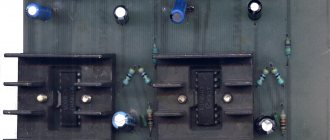
The simplest and highest quality amplifier is an amplifier implemented using an emitter follower circuit. Such circuits are called Class A amplifiers. Their characteristic is that the quiescent current (current when there is no input signal) must be at least as large as the maximum output current at peak signal values. As a result, the circuit dissipates significant power at rest.
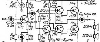
In Fig. Figure 1 shows a circuit of a 10 W repeater that drives a load with a resistance of 8 ohms.
Fig 1
The input signal of the circuit can vary over a range of ± 15 V peak and deliver 10 W of power to the load (9 V rms into 8 ohms). In the absence of a signal, the output transistor dissipates 55 W of power, and the emitter resistor dissipates another 110 W!
Despite such power losses, the circuit still finds application due to its low level of nonlinear distortion. However, due to its low power, this circuit is not used in concert systems.
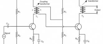
Class B
In Fig. Figure 2 shows a circuit of a push-pull repeater.
Fig 2
Transistor T1 is open for positive signal values, and transistor T2 is open for negative signal values. At zero input voltage, there is no collector current and no power is dissipated. At 10 W output power, each transistor dissipates less than 10 W power.
Transient distortion in push-pull stages
The diagram in Fig. 2 has the following property: the output signal tracks the input signal with the difference in voltage drop UBE; at a positive interval of the input signal, the output voltage is approximately 0.6 V less than the input, and at a negative interval it is greater. For a sinusoidal input signal, the output signal will be as shown in Fig. 3.
Fig 3
This type of distortion is called transient or “step” type.
To reduce transient distortion, the push-pull stage is biased to the conduction state. In Fig. 4. The simplest bias circuit is shown.
Fig 4
Bias resistors R cause the diodes to conduct, causing the voltage at the base of T1 to exceed the input voltage by the amount of voltage drop across the diode. Same for T2. Now, when the input signal passes through zero, T2 becomes the conducting transistor instead of T1; one of the output transistors is always open.
Such circuits are called class B amplifiers. They have one serious drawback - they are not temperature stable. As the output transistors heat up, the collector current increases. This causes the release of additional heat and the possibility of uncontrolled positive thermal feedback (self-heating) occurs, which leads to failure of the transistors. Even if this does not happen, it is necessary to ensure more reliable operation of the circuit.
Class AB
Among various circuit solutions in the field of professional theater and concert sound reinforcement, class AB amplifiers made on bipolar transistors are the most popular due to their efficiency, a fairly low level of nonlinear distortion and the relative simplicity of the circuit design.
These push-pull amplifiers use bias to produce a sufficiently large quiescent current at the moment the signal passes through zero. It is assumed that both transistors are in conduction state for some time interval. When choosing quiescent current, a compromise is sought between reducing distortion and power dissipation at quiescent state. To increase temperature stability, sometimes very sophisticated bias circuits are used. Deep negative feedback is almost always used to reduce transient distortion.
Class D
They are also called PWM amplifiers, and this is correct, but calling them “digital”, as sometimes happens, is completely wrong. In these amplifiers, the output transistors operate in switching mode. The signal amplified by the output transistors is a width-modulated high-frequency pulse (hundreds of MHz). Theoretically, the efficiency of such an amplifier can approach 100%, because the output transistors are either closed and there is no current through them, or completely open, and the current flows into the load, causing virtually no voltage drop across the transistors. Losses occur in transistors at the moments of their switching (short-term class A mode) and, obviously, depend on the speed of the transistors and the pulse repetition rate. At the same time, increasing the pulse frequency improves the sound quality of the amplifier. This is just one of the trade-offs that arise when designing pulse-width amplifiers. In addition, these amplifiers are characterized by a high level of electromagnetic radiation, circuit complexity and low maintainability - touching some points with an oscilloscope probe can lead to failure of most of the circuit. However, repairing these amplifiers usually comes down to replacing modules or boards, and manufacturers produce a sufficient range of repair kits.
But, as said, these amplifiers have an incredibly high efficiency, more than 90%, i.e. Almost all the energy consumed is converted into an audio signal, while traditional amplifiers have an efficiency of around 50%. In addition, PWM amplifiers are often equipped with power factor correctors, i.e. when the network voltage drops, they do not reduce the output signal level, which is a very important advantage for our conditions.
Amplifier parameters
- Power. Normalized at a certain level of harmonic distortion. Sometimes two power values are published for two different harmonic distortion levels.
- Level of nonlinear distortion (THD). It is assessed, first of all, by the harmonic coefficient - the ratio of the root-mean-square sum of the voltage (or current) of the higher harmonics of the signal, resulting from nonlinear distortions, to the voltage (or current) of the fundamental frequency.
- Intermodulation distortion (IMD) level. Distortions manifest themselves in the form of the appearance of sum-difference (combination) harmonics that arise as a result of nonlinearity when two harmonic signals are supplied. They are quite noticeable to the ear.
- Dumping factor (damping factor) is the ratio of the load resistance to the output impedance of the amplifier. A higher value of the damping factor contributes to better reproduction of the attack of the sound signal and less manifestation of the resonant properties of speaker systems.
- Frequency response - the frequencies reproduced by an amplifier at a normal level of roll-off and rise (flatness), typically ±0.5 dB for the range 20 Hz...20 kHz, or +1/-3 dB for the range 5 Hz...100 kHz.
- Signal-to-noise ratio (dB) is the ratio of the maximum signal level at acceptable distortion to the level of internal thermal noise of the amplifier elements in the absence of an input signal.
- Crosstalk (dB). The degree of signal penetration from channel to channel.
Amplifier efficiency
The efficiency of push-pull amplifiers without taking into account the quiescent current and other thermal losses (usually insignificant) is 0.5. To increase the efficiency in high-power amplifiers (more than 0.5 kW), ingenious circuits with stepped power supplies are sometimes used. That is, when operating on small signals, the amplifier is powered from a low-voltage source, and when operating on large signals, from a high-voltage source.
"Transistor" sound
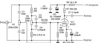
Despite all the tricks, such as the introduction of deep negative feedback, the use of sophisticated push-pull amplifier bias circuits, etc., BJT amplifiers have a harsh or “transistor” sound. This is reflected not so much in the technical parameters, which are excellent in modern amplifiers, but in the results of expert evaluations of the amplifiers. This is due to the properties of the bipolar transistor to abruptly enter the conduction state and produce deep saturation at maximum signals. As a result, the spectrum of harmonic distortion of amplifiers based on bipolar transistors is very wide (up to the 11th...15th harmonics), rich in “unpleasant” odd harmonics, which gives rise to a characteristic sound even with a low overall level of harmonic distortion. The best indicators in this sense are field-effect transistors (MOSFETs) and vacuum tubes (Fig. 5). Therefore, amplifiers made on these devices occupy their worthy niche in the total mass of audio equipment.
Fig 5
Amplifier stability
In some amplifiers, under certain operating conditions, self-excitation may occur, i.e. generation at high (ultrasonic) frequencies. This is facilitated by the large feedback depth of the amplifier circuit and the complex nature of the speaker impedance. Naturally, most of all this goes to the high-frequency components of speaker systems. To prevent self-excitation, special circuits are introduced into amplifier circuits and higher frequency components are used.
Amplifier components
Perhaps, the parameters of the output transistors most strongly determine the overall performance of the amplifier. In addition to the maximum permissible values (maximum voltage, current, power, temperature), parameters such as the thermal resistance of the housing, saturation voltage, etc. are also important. Dynamic (speed) parameters are very important. The faster the transistors, the greater the depth of feedback possible without the risk of self-excitation. In transistor production technology, a number of parameters are compromises. Therefore, to achieve high power, the required number of transistors is connected in parallel, but then another parameter becomes important - the spread of parameters.
The requirement to combine the parameters of output transistors has always forced manufacturers to look for transistors manufactured using the most advanced technologies of their time.
Design
Amplifiers intended for concert use must have a durable rack design. Fans are used for forced cooling. In “advanced” models, the fan speed is made dependent on the temperature of the output transistors. This helps reduce dust accumulation inside the amplifier housing. The organization of the cooling air flow is also important. It is better when the main flow passes through special tunnels, cooling the output transistors and covering less of the remaining circuits. It is also welcome to have an air filter that can be easily cleaned.
The circuit connections must also be very reliable. It should be borne in mind that unreliable contacts (both breaks and short circuits) often lead to failure of the amplifier, and sometimes the entire speaker system.
In general, it should be noted that in concert sound systems, amplifiers are the most vulnerable place. Indeed, circuit components, operating at very high voltages and currents, are exposed to all sorts of, sometimes severe, external influences, such as high temperature, humidity, vibration, aggressive environments (wind and spray from the sea, ash from fireworks, etc.). Not to mention such everyday things as power overloads and instability of the electrical network voltage. Therefore, high reliability of amplifiers is one of the most important conditions for successful concert events.
Features of the circuitry of concert amplifiers
Standard are two-channel (two amplifiers in one housing), the presence of symmetrical (balanced) inputs and the possibility of bridge (BRIDGE) connection.
With bridge connection, the input signal is supplied to one channel of the amplifier directly, and to the second through an inverter. The load is connected between the channel outputs. In this case, the voltage across the load and, accordingly, the current is twice as high as with normal switching on. Therefore, the load impedance when bridged is connected must be twice as large. That is, if for each amplifier channel the minimum load impedance is normalized as 4 Ohms, then for bridged connection it is normalized to 8 Ohms. (Figure 6).
Rice. 6
As accessories, some manufacturers offer a set of built-in, built-in or included in the rear panel modules, which can be limiters, crossovers, balanced transformers, etc.
Amplifier protection
In the music industry, audio equipment is sometimes used under very difficult conditions. Therefore, manufacturers of high-power amplifiers take all possible types of protection. These include protections:
- from exceeding the maximum signal level (as a rule, an RMS limiter is used, sometimes disabled);
- from exceeding the maximum output current;
- from overheating;
- from the appearance of constant voltage;
- from the loss of one of the supply voltages;
- from a click when turning on the speakers (delay).
Some models have built-in speaker protection. This is usually a triac that short-circuits the output of the amplifier in emergency situations and thereby saves the speaker systems.
September 15, 2015
Stanislav Baranov
About damping
The speaker itself is a rather complex oscillatory system, which can have several resonance frequencies (mechanical resonance, resonances of the suspension, diffuser...). And when any signal is reproduced, oscillations occur at resonant frequencies. And if the damping is weak, then even after this signal disappears, damped oscillations can continue. This, in turn, will accompany the reproduction of sounds with additional overtones that color the sound.
When designing and manufacturing acoustics, it is important to correctly take this factor into account and dampen the loudspeaker so that its own vibrations decay as quickly as possible. There are only three means for damping the speaker, which were mentioned just above:
- Mechanical damping. Here the losses due to internal friction in the suspension are determined.
- Acoustic damping. Acoustic design has its own characteristics that you need to know, understand and not forget about.
- Electrical damping. This means is determined by the output impedance of the amplifier. Often, in the parameters of the amplifier, such a parameter as the “dumping factor” is indicated.
A little expanded.
Mechanical damping of the head is laid out at the design stage. The design feature of the dynamic head is determined and then, later, it is almost impossible to change this parameter in any way. Here we are powerless.
Acoustic damping is quite feasible. It is this parameter that is easiest to change and improve the indicator. Change how? Glue the inside of the acoustic body with vibration and sound-absorbing material (we talked about this many times and gave examples even from our own experience, when finalizing the acoustics). You can also change the design of the mid-frequency and high-frequency speakers. There's a lot of room for improvement in this factor here, as long as you don't overdo it too much.
But another factor makes a more significant contribution to damping - electrical damping . This is the main tool for influencing transient processes between the speaker and the amplifier. And here we cannot change anything, because amplifiers are produced by huge factories where a large number of specialists and engineers work - they know what to do. But don’t be upset here - amplifier manufacturers know about this parameter and take care of compliance with the necessary technical specifications.
Very often, manufacturers do not indicate this parameter (dumping factor) in the documents for the amplifier, but this does not matter. Today, almost all amplifiers meet the requirements on this issue.
- Home page
- Amplifiers
- Amplifier characteristics
When choosing a power amplifier, buyers often make a similar mistake, believing that the technical characteristics indicated in the passport will allow them to understand what kind of sound they should expect from the amplifier they are purchasing. The fact is that the main parameters do not reflect the “character” of the amplifier, if only because they were measured in refined laboratory
conditions and may generally be unreliable. Amplifiers with equal technical characteristics may sound different. And it happens that an amplifier with worse characteristics sounds much better. It can be assumed that these phenomena are mainly associated with the subjective perception of the sound field by different people. However, it is more correct to assume that if there are differences despite the same “figures,” this means that they simply forgot to measure something. As a result, it turns out that evaluating an amplifier based on its basic characteristics is the same as evaluating a person only based on his physical parameters.
The main characteristics of an audio power amplifier include:
- Output power.
- Frequency range.
- Harmonic distortion factor.
- Signal to noise ratio.
- Dumping factor (or damping coefficient).
Additionally, the following may be indicated:
- Intermodulation distortion factor.
- Output voltage slew rate.
- Crosstalk.
Of course, the passport also contains important performance characteristics:
- Supply voltage.
- Maximum power consumption.
- Weight.
- Dimensions.
output power
This parameter has many varieties and measurement techniques, and some manufacturers use this for advertising purposes, deliberately not indicating the conditions under which the output power was measured. That is why the buyer is perplexed when comparing in a store a tiny music center with a 2x1000W sticker and a weighty power amplifier of impressive size with a characteristic of 30 W per channel.
For domestic amplifiers, characteristics such as rated and maximum output power were mainly used:
Rated power is the output power of the amplifier at a given nonlinear distortion factor. This measurement technique provides a certain freedom of choice to the manufacturer, who is free to specify the rated power value that corresponds to the most favorable value of non-linear distortion. But it is widely known that in class AB amplifiers at low output power levels, for example 1W, the level of distortion can reach enormous values. It can decrease significantly only when the output power is increased to the rated value. In the passports of domestic manufacturers, record rated characteristics were indicated, with an extremely low level of distortion at a high rated amplifier power. Whereas the highest statistical density of a musical signal lies in the amplitude range of 5-15% of the maximum value. This is probably why Soviet amplifiers were noticeably inferior in hearing to Western amplifiers, whose distortion could be optimal at medium volume levels. In the USSR, there was a race for a minimum of harmonic and sometimes intermodulation distortion at any cost at one nominal (almost maximum) power level.
Maximum power – the output power of the amplifier at an unstandardized nonlinear distortion factor. This parameter is even less informative than the rated power and characterizes only the safety margin of the amplifier - the ability to operate for a long time under input overloads.
Among foreign ones, the most commonly used characteristics are RMS, PMPO and DIN POWER:
RMS (Root Mean Squared) – root mean square power value at normalized nonlinear distortion factor. As a rule, the measurement is carried out at 1 kHz when the harmonic distortion factor reaches 10%. This indicator was borrowed from electrical engineering and, strictly speaking, is unsuitable for describing sound characteristics. In musical signals, a person hears loud sounds better than weak ones, since the hearing organs are affected by amplitude values, not root-mean-square values. Thus, the average value will have little to say. The RMS standard was one of the unsuccessful attempts to describe the parameters of audio equipment and has very limited application - an amplifier that produces 10% distortion not at maximum power needs to be looked for. Until maximum power is reached, distortion often does not exceed hundredths of a percent, and then increases sharply.
PMPO (Peak Music Power Output) - the maximum achievable peak value of the signal, regardless of distortion, in a minimum period of time (usually 10 mS). As follows from the description, the PMPO parameter is virtual and meaningless in practical use. However, it is very often found in descriptions of amplifiers, misleading many buyers. In this regard, one can only complain about the lack of uniform mandatory standards for measuring output power and the dishonesty of manufacturers. 100 W PMPO often corresponds to only 3 W rated power at 1% THD.
DIN POWER - the value of power output at a real load at a normalized nonlinear distortion factor. Measurements are carried out for 10 minutes using a signal with a frequency of 1 kHz when 1% SOI is reached.
This parameter most adequately characterizes the output power of the amplifier. Sometimes it is found in the amplifier data sheet under the designation IEJA. Its IHF variant specifies power output at 0.1% THD.
Strictly speaking, there are many other types of measurements, for example, DIN MUSIC POWER, which describes the power of a musical signal rather than a sinusoidal one. Recently, due to the lack of a uniform standard, manufacturers are trying to indicate the output power along with other characteristics at which it is measured. For example,
650 W (8 Ω, 20 – 20000 Hz, 0.1% THD) 750 W (8 Ω, 1000 Hz, 0.1% THD)
Considering the fact that a music signal has a large frequency and dynamic range, it is more correct to carry out measurements using music signals. And indicate not the rated power, but a graph of the dependence of the nonlinear distortion factor on the output power.
It can be added that each amplifier is designed for a certain load resistance. However, it can vary, and technical data sheets indicate the main parameters for each allowable resistance.
frequency range
Almost any modern audio power amplifier is capable of amplifying signals with frequencies far beyond the audible range. Therefore, indicating the frequency range in its pure form, for example, from 5 Hz to 100 kHz, is completely pointless.
The purpose of an audio frequency power amplifier (if it does not have a special purpose, such as a guitar amplifier) is to generate an electrical signal at the output, the shape exactly repeating the input signal, but having greater power. Since a musical signal, even if it is generated by one musical instrument, is far from harmonic, minimizing the coefficient of nonlinear distortion in amplifiers for high-quality sound reproduction is not enough. It is necessary that in the range of audible frequencies from 16 to 20,000 Hz, the amplitude-frequency and phase-frequency characteristics of the amplifier are absolutely horizontal. In practice, this cannot be achieved, and the acoustic system has an frequency response with more significant dips and rises.
frequency range
indicated with normalized unevenness of the amplitude-frequency characteristic, expressed in relative values. The most successful amplifier models have an uneven frequency response of +/-0.1 dB in the range from 20 to 20,000 Hz. If we take the standard unevenness of the amplitude-frequency response of 3 dB during measurement, then the frequency range will be 10 - 100,000 Hz.
Harmonic Distortion Factor
Signal distortion is caused by the nonlinearity of the input and output characteristics of the amplification elements and is inherent in any power amplifiers. If you apply a sinusoidal signal to the input of the amplifier, then in the spectrum of the output signal, in addition to the main harmonic, additional harmonics will be found, the frequency of which is a multiple of the frequency of the useful signal. Such harmonics are parasitic and their power is usually small. However, their summation with the useful signal leads to a significant distortion of its shape, and as a result, distorted sound.
Total Harmonic Distortion shows the audible component of harmonic distortion in the output signal and is defined as the ratio of the total power of the spurious signals to the power of the useful harmonic signal. Typically, measurements are carried out at a frequency of 1 kHz.
When taking measurements, attention is paid to the spectral distribution and nature of distortion. The audibility of parasitic harmonics depends on the relative level in relation to the test signal, on the order of the harmonic, on the type (even/odd), and also on the volume at which the test fragment is heard.
A typical THD value for a Hi-Fi amplifier is 0.1%. However, it has been noted more than once: an amplifier with a THD of 0.001% may sound worse than another with a THD of 0.1%. The fact is that with such small values of this parameter, distortion is difficult to trace in the form of the output signal or to be felt by ear. Therefore, the difference between 0.1% and 0.001% will not be heard.
Signal to noise ratio
The signal-to-noise ratio is defined as the ratio of the power of the useful harmonic signal to the power of the power amplifier's own noise. This parameter for modern sound reinforcement equipment exceeds 100 dB. This means that the power of the amplifier's own noise is 10 billion times less than the power of the useful music signal. It is safe to say that at present this parameter is only a source of pride for the manufacturer. It has no meaning for the user. Who can feel the difference between 95 and 100 dB SNR?!
Dumping factor (damping coefficient)
The damping coefficient is defined as the ratio of the nominal load resistance to the output impedance of the amplifier and characterizes the ability to suppress parasitic voltages that arise in the dynamic heads when the coil moves in a magnetic field. If the damping is insufficient, then the diffuser will make its own “body movements”, which have nothing to do with the music, but depend on the elasticity of the suspension. It should be noted that in the vast majority of speaker system models this problem is successfully solved. It can be considered sufficient if the coefficient value exceeds 100.
Damping depends not only on the output impedance of the amplifier and the impedance of the speaker system. It must be taken into account that the ability to absorb the energy returned by the loudspeaker depends on the inductances of the filters and on the resistance of the connectors and cables to which the speakers are connected.
The minimum value of the damping coefficient can be considered 20, good - 150-400. Modern high-end amplifiers have a value of this parameter of 150 or higher.
Intermodulation distortion factor
The nonlinearity of the characteristics of the amplifying elements leads to the occurrence of nonlinear distortions. Most amplifier manufacturers only measure and list harmonic distortion (THD). The measurements are carried out using a harmonic signal. During such testing, higher harmonics appear at the output of the amplification path, the frequency of which is a multiple of the fundamental frequency. However, as already mentioned, the musical signal is far from harmonic. Moreover, any musical instrument reproduces not only the fundamental tone, but “overtones,” which are a prime example of harmonic distortion. It is known that the presence of “overtones” in a musical signal does not spoil, but enriches the sound. Therefore, it is very important to indicate not the harmonic distortion coefficient, but the entire spectrum of the output signal, from which you can determine the type (even or odd) of parasitic harmonics and their level relative to the useful signal. From the point of view of psychoacoustics, for example, the presence of even-numbered harmonics in the output signal is perceived better by ear than the presence of small odd-numbered ones.
The greatest harm to a musical signal comes from intermodulation distortion (Inter Modulation Distortion), which occurs when a multi-tone signal is applied to the input of a nonlinear system. In this case, parasitic signals appear at the output with frequencies that are the sum or difference of frequencies of the input signals, as well as the sum or difference of frequencies of signals caused by harmonic distortions and returned through feedback to the input of the amplifier. Such distortions do not correlate with the fundamental tones of the music signal and introduce background noise into it.
It should be noted that there are no uniform standards for measuring intermodulation distortion, and measurement results significantly depend on the levels of input signals and their frequencies. Most often, IMD is not indicated simply because it is not known how to measure it. Nevertheless, this parameter is the most promising for assessing the nonlinear properties of a power amplifier.
Output slew rate
This parameter characterizes the level of dynamic distortion that arises as a result of limiting the slew rate of the output signal in an amplifier covered by deep feedback. The introduction of OOS, as a rule, leads to instability of the amplifier at high frequencies. This forces the use of frequency correction. In turn, the cutoff frequency of the formed low-pass filter is not high enough and causes dynamic distortion.
The musical signal always contains sharp spikes in level, for example, when playing percussion instruments. Insufficient slew rate of the signal leads to deterioration of the sound, which is expressed in a loss of energy.
Crosstalk
This parameter determines the degree of signal penetration from one channel to another. A high level of crosstalk leads to a slight deterioration in stereo clarity. However, a sensitive listener will immediately feel that the sound does not give an idea of the relative position and size of musical instruments, i.e. absence or unclearness of the 3D sound picture.
Last but not least, when choosing an amplifier, attention is paid to its appearance and ease of use. Due to subjectivity, these indicators cannot be measured in any way and are expressed in the form of stars in numerous ratings and “Gold Design” stickers on the device body. Without a doubt, this is also a characteristic of a power amplifier.
Some numbers, but no formulas
Now a little science. There is a standard of the last century, used in Hi-Fi technology - DIN45500. In accordance with it, the minimum value of the dumping factor must be at least 20 units. How did you come to this? There is a story about how this dependence was experimentally discovered. In the 20th century, at the dawn of the search for high-quality sound, tube amplifiers were used that had high output impedance. As a result of experiments, it was concluded that the minimum value of the damping coefficient should be from 5 to 8 units, no less.
But after the advent of transistor amplifiers, this parameter was improved without much difficulty, and that standard was adopted - at least 20 units.
How do you understand what these units are? If not scientifically, but from practice, how and in what way is this expressed? This means that the amplifier output resistance when working with 4 Ohm acoustics should not be higher than 0.2 Ohm. But each conductor (wire) has its own resistance. As we have already measured here (Which wire is better to connect the acoustics?), the wire has resistance anyway. And it turns out that the wire (cable) that connects the amplifier and the acoustics contributes to this damping factor.
Today, any self-respecting company producing radio equipment brings the dumping factor figure to the ideal. It is not often possible to find readings of this parameter in the characteristics below 50-70 units. And when using class D amplifiers, the parameter looks absolutely fantastic - 2000 and above. And they are trying to present this parameter as the most important of all, although in reality it is not so important. But more on that below.
A little theory
In reality, amplifiers have some output impedance. In a good design it is very small, on the order of hundredths of an ohm. The DF expresses this as a ratio to the load impedance, so an amplifier with an output impedance of 80 milliohms loaded into an 8 ohm speaker will have a DF of 8/0.08=100. An amplifier with an output impedance of 8 milliohms will have a diffraction factor of 8/0.008=1000. Damping factors vary greatly, but the difference in amplifier performance is only a small fraction of an ohm.
It is not always understood that the DF changes depending on frequency, remaining constant at low frequencies (say up to 1 kHz) and falling in the high-frequency part of the range. The data sheet always gives the value at low frequencies.
The problem with the term Damping Factor is that the name makes it sound like it has a big effect on the damping of the speaker, but it doesn't. Of course, the resonance of a woofer driver is affected by the series resistance of its electrical circuit, but almost all of it consists of the resistance of the speaker coil, which is usually in the range of 5-7 ohms. The crossover (filter) adds about 1 ohm, and the connecting cable also adds about 1/4 ohm. It is clear that the output impedance of a good amplifier is a very small fraction of this impedance, and thus the difference between a DF 100 and a DF 1000 in terms of loudspeaker damping is negligible. (In addition, the low-frequency resonance of a loudspeaker is carefully selected by its designer and arbitrarily changing it is unlikely to improve the sound.)
This doesn't mean that the amplifier's output impedance doesn't matter. The load that a loudspeaker presents to an amplifier is highly dependent on frequency, so if the output impedance is high, the output level will vary with frequency, introducing undesirable changes to the frequency response of the system. The lower the output impedance, the better.
Speaker cable as a component of the dumping factor
As the professionals say: “the best cable is the absence of one!” What does it mean? To connect the acoustics to the amplifier, of course, you need a wire. And there is a lot of controversy about its length, quality and cross-section. But one thing is true here - the shorter the better! We won’t go too deep here, but let’s look a little at the effect of cable length on the dumping factor.
A speaker cable can significantly spoil the sound quality of the acoustics. The resistance of the amplifier itself is added to the resistance of the cable and all this becomes a component of the dumping factor. For example, a cable approximately 2 meters long with a resistance of 0.04 Ohm is a very decent indicator. But, if the amplifier has an output impedance of 0.01 Ohm, then at a load of 4 Ohms with such a cable, the damping factor will decrease from 400 to 80. There is no reason to worry too much, there will be no significant reduction in the quality of the reproduced sound.
But as we have already discussed here (How to choose a cross-section for an acoustic cable?) the dumping factor can drop to 10. And here no “sophisticated” parameters of the amplifier and acoustics will “stretch” this factor to an acceptable level.
You can often hear or read in reviews that after replacing the “standard” speaker wires with “normal” ones, the “correct bass” appears, and the sound becomes more intelligible, the acoustics seem to begin to sound differently. And all because when using a normal wire, the speakers' dynamics are better controlled by the amplifier, and the electrical damping rate increases sharply. We get an accurate, rich sound picture, without unnecessary overtones.
Therefore, when choosing an acoustic wire, it is important to take into account the moment - the resistance of the resulting circuit. We do not take the amplifier itself into account. We “imply” that it initially meets the required output resistance parameters.
Example of dumping factor calculation
For example, there is an acoustic system with a resistance of 6 ohms. We divide this value by the minimum desired DF indicator, for example by 30. It turns out 0.2 Ohm.
Then we calculate the length of the wire, or rather the resistance along the entire length. For example, wires with a cross-section of 1.5 mm2 are laid along the baseboard and the total length is 7 meters in one direction and plus another 7 in the other direction, for a total of 14. The resistance was calculated to be 0.6 Ohm. This wire is not suitable. This wire requires acoustics with a resistance of 16-18 ohms.
Let's quickly calculate the damping factor for 16-ohm acoustics. 16 ohms / 30 = 0.53 ohms. And for a 6-ohm one it should be 0.2 ohms. The difference is significant, however.
There is a way out - use acoustic wire with a cross section of 2.5 mm2. Its resistance will be significantly less and the dumping factor will be normal.
Can this dumping factor be heard?
Only a professional with a trained ear (hearing) can immediately hear and understand that something is wrong. He has heard a lot of things and will understand what is wrong with the sound. But for ordinary music lovers, this problem with the dumping factor, in my opinion, is a big deal.
When calculating the length of the wire, you just need to take into account its cross-section. Do not use twists. And then you can get a tangible “plus” from the acoustics and amplifier while listening to your favorite compositions. As for the gold-plated terminals and silver-plated wires, “ski ointment” - this is a purely personal matter, but that’s another story.
conclusions
To summarize all that has been said, I will try to briefly formulate my conclusions related to the concept of dumping factor:
- Questions about the damping coefficient are important only in the low-frequency spectrum, where the influence of the complex impedance of the acoustics is quite large;
- Short speaker cables (up to 4-6 meters), with a cross-section of at least 1.5 mm², do not have a significant impact on the damping factor of a modern amplifier and on the entire resulting sound picture;
- Speaker systems with high output power, which are connected by long wires, require significant costs for the speaker cable (its cross-section). This is an important point;
- If you try to independently calculate the required parameters of an acoustic cable, then as a basis you can take the resistivity value of a cable with a cross-section of 2.5 mm² of 0.006 Ohm per 1 meter. It will be right.
- Standard wires and thin cables for acoustics (for example, in 5.1 acoustics), from almost all manufacturers, must be replaced with acoustic wires with a cross-section of at least 1.5 mm2, preferably 2.5 mm2. This is another useful finding.
- I don’t particularly worry about this dumping factor, since technology and the development of amplifier circuits are already “established”, and therefore do not require special attention to studying the characteristics of the purchased amplifier specifically for this parameter.