Tube ULF
A selection of single-ended tube ULF circuits (6P1P, 6Zh1P, 6F3P, 6N23P, 6N2P, 6P14P)
Tube amplifier circuits (including historical ones) were selected based on a combination of technical solutions, with highlights if possible. And everyone’s tastes are different, so don’t blame them if you didn’t guess right... In the old schemes, a number of denominations are brought to the standard. The simplest in circuit design are single-ended...
2 286 0
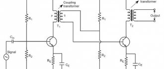
Seven circuits of push-pull tube amplifiers (EL84, 6P14P, 6P6S, 6F3P, 6N6P)
Let me make a reservation right away - this anthology in no way claims to be a manual on tube circuitry. Schemes (including historical ones) were selected based on a combination of technical solutions, with, if possible, “highlights”; And everyone has different tastes, so don’t blame me if you didn’t guess right... In the old...
1 268 0
Impromptu - 50 Watt tube UMZCH (6S41S, 6ZH9P)
The tube power amplifier circuits in the articles presented by the authors (see the list of references) are distinguished by their originality, thoughtfulness and good parameters. So in this article, a simple 50-watt UMZCH is proposed, in which you can use ready-made output and unified network ...
4 9283 0
Three-tube stereo audio amplifier for 6N23P and 6P14P (ECC88, EL84)
Circuit diagram of a homemade stereo low-frequency power amplifier, assembled using a 6N23P tube and two 6P14P tubes. Foreign analogues of these lamps are ECC88 and EL84. The proposed tube ULF has the following characteristics: Reproducible frequency range - from 20Hz to 80kHz; Output power in triode mode - 2 x 2.75 W; Output power in pentode mode is 2 x 4.5 W.
1 7655 3
Tube audio amplifier for 6S2P, 6P18P (12W)
Good afternoon, dear radio amateurs. As you know, history develops in a spiral, and the history of the development of audio technology is no exception to this. If you look at the playback amplifier market, you will notice that in the last few years there has been a reincarnation of tube amplifiers, and some manufacturers have resumed production of radio tubes. Today we would like to offer you the design of a simple tube amplifier designed...
3 7200 1
Single-stage tube UMZCH 4W (6P9), diagram and description
The article describes the design of a single-stage low-power tube UMZCH, used by the author in conjunction with speakers built on the basis of high-sensitivity broadband heads. The amplifier uses parallel connection of two 6P9 pentodes, characterized by high gain. This made it possible to obtain an output power of up to 4 W when working with a signal source providing a signal voltage of up to 1.5...2 V, i.e. from any CD player or smartphone...
1 9120 1
Home tube vinyl corrector (EF86, 6N2P)
This article is intended for vinyl lovers who have at least basic knowledge of radio engineering and know how to hold a soldering iron in their hands. Despite the abundance of digital audio sources, many of us still have a large collection of vinyl records. Moreover, the sound quality is decent for the recorded...
1 8499 0
Tube amplifier with transformers TPP-258-127/220-50 (6N8S and 6P3S)
Schematic diagram of a homemade tube power amplifier for 6N8S and 6P3S, which uses factory transformers of the TPP-258-127/220-50 type. The author tells how he made the amplifier and what changes he made to the UMZCH circuit; photos of the disassembled and finished device are also provided.
1 9171 5
Circuit of a push-pull tube power amplifier for 6P14P (8 Watt)
The push-pull output stage of the stereo amplifier is distinguished by the use of a common current generator on the microcircuit in the cathode circuit, thanks to which paraphase control of the 6P14P pentodes is ensured. By choosing the load resistance transformation ratio you can change to some extent...
2 12088 17
Simple tube power amplifier for 14-20 Watts (6N2P, 6P14P)
The AF power amplifier, the circuit of which is shown in the figure, is made using lamps from old black-and-white TVs or radios. This is a pre-amplifier with a bass reflex on a 6N2P double triode and a push-pull output stage on two 6P14P tubes. The use of such old components is often...
14 26526 23
1 …
↑ Scheme from my project
As a result, I assembled a hybrid circuit with a higher current driver relative to the original and the original terminal, but without feedback.
In the diagram you can see the vinyl corrector block, which I will talk about a little later.
The high-resolution diagram is in the archive below. Resistors from 0.5 to 2 Watt MF 5%, 5 Watt Chinese ceramic. I would like to note that in my version of the driver, anode resistors (R30 in the diagram) should be used with a power of 5 Watts (2 Watt resistors will turn black). I used film capacitors for all interstage capacitors for a voltage of 400 Volts.
Assembly
Let's start the assembly with the pre-amplifier. Its installation follows a fairly simple scheme. It is also necessary to provide power control and a separator for tone control. It should be tuned to low and high frequencies. To increase shelf life, you need to use a multi-band equalizer.
In the laughter of the preamplifier you can see similarities with the common 6N3P double triode. The element we need can be assembled in a similar way, but use the final cascade. This is also repeated in stereo. Remember that the structure must be assembled on a circuit board. First it needs to be debugged, and then it can be installed on the chassis. If you installed everything correctly, the device should turn on immediately. Next you should move on to configuration. The value of the anode voltage for different types of lamps will differ, so you will need to select it yourself.
Housings
As it turned out, making a housing for a tube amplifier that is pleasing in appearance and suitable in all respects is not a trivial task. The walls of the housing must be thick so as not to sag under multi-kilogram transformers, of which there are as many as 5 pieces. Holes for lamps, connectors and switches must be calculated and cut to the nearest millimeter. You also need internal screens, ventilation slots, etc. As a result, we had to create a 3D model so that all the details could be finalized.
3D model of the amplifier
After making the case from steel and the front panel from aluminum, all the holes were cut using laser cutting. Next, the body was sent for painting. With the phono stage everything turned out to be somewhat simpler. The only thing was that we had to adjust its appearance and height to the amplifier body so that they looked in the same style. To make it even more beautiful, arms, legs and other little things were ordered ready-made from Aliexpress.
There was one more important thing left - putting inscriptions on the front panels. Because I initially wanted the case in black; the option of applying laser engraved inscriptions was out of the question. I had to look for companies that could handle this. The first logical option was silkscreen printing. But no one wanted to take on a couple of panels, and with a minimum order of 20 pieces, the price was no longer quite adequate. The next option was companies producing all kinds of advertising with their advanced printers. Most places I've applied to have turned me down, either because the surface of the panels is rough and the paint will float, or because the panel needs to be flat to print and not have pins protruding from the back. But fortunately, an organization was found that agreed to take on the order and completed it at the proper level.
Front panels after labeling
Capacitors
In a tube amplifier setup, you should use different types of capacitors for the system itself and the power supply. They are usually used to adjust the tone. If you want to get high-quality and natural sound, you should use a coupling capacitor. In this case, a small leakage current appears, which allows you to change the operating point of the lamp.
This type of capacitor is connected to the anode circuit, through which a large voltage flows. In this case, it is necessary to connect a capacitor that maintains a voltage greater than 350 volts. If you want to use quality parts, you need to use parts from Jensen. They differ from analogues in that their price exceeds 3,000 rubles, and the price of the highest quality radio elements reaches 10,000 rubles. If you use domestic elements, it is better to choose between the K73-16 and K40U-9 models.
Removing Interference
Later, you need to eliminate the low-frequency background, if, of course, it is present. Another important point is the choice of grounding point. In this case, you can use one of the options:
- The type of connection is a star, in which all “ground” conductors are connected to one point.
- The second method is to lay a thick copper busbar. It is necessary to solder the corresponding elements onto it.
In general, it is better to find a grounding point yourself. This can be done by determining the level of low-frequency background by ear. To do this, you need to gradually close all the grids of lamps that are located on the ground. If, when the subsequent contact is closed, the low-frequency background level decreases, then you have found a suitable lamp. To achieve the desired result, it is necessary to experimentally eliminate unwanted frequencies. You should also apply the following measures to improve the quality of your build:
- To make filament circuits for radio tubes, you need to use twisted wire.
- Tubes used in the preamplifier must be covered with grounded caps.
- It is also necessary to ground the housings with variable resistors.
If you want to power the preamp tubes, you can use DC current. Unfortunately, this requires connecting an additional unit. The rectifier will violate the standards of a Hi-End tube amplifier, since it is a semiconductor device that we will not use.
↑ Fighting the background
I assumed that there should be no background, because I made the printed circuit board according to all the rules for wiring the ground in tube amplifiers.
But there was a background. Comrades from our forum gave a lot of advice on how to eliminate it, but the result was still the same. The solution was the article “On the installation of signal circuits in a tube amplifier,” which was posted by Igor Kotov several years ago. (I highly recommend reading it and bookmarking it - it will save you a lot of nerve cells). I performed the so-called double shielding of the interconnect cable and the background disappeared. The problem was interference in a fairly reliable (as I myself assumed) cable from the computer to the amplifier.
Unique device
Hi-End tube amplifiers are a special class of household appliances. What is this connected with? Firstly, they have some pretty interesting design and architecture. In this model, a person can see everything he needs. This makes the device truly unique. Secondly, the characteristics of a Hi-End tube amplifier differ from alternative models that use transistor integrated circuits. The difference between Hi-End is that a minimum number of parts are used during installation. Also, when evaluating the sound of this device, people trust their ears more than nonlinear distortion measurements and an oscilloscope.
Parameters and description of the kit
- Rated power: 25W RMS
- Input sensitivity: 1.5V
- Input impedance 100 kohms
- Input Connector: Linear RCA
- Speaker output: 4 and 8 ohms
- Distortion: Less than 0.5% half power, 1% full power.
- Frequency range: 8 Hz - 20 kHz +0/-1dB at rated power
- Signal to noise ratio: less than 80dB
- Lamps: Gold Lion KT88, NOS JAN Philips 5751
- Power consumption: 80 W (each monoblock)
- Weight: 6 kg (each monoblock)
- Dimensions: 200 mm (W) X 220 mm (H) X 300 mm (D)
↑ Settings for the balance of the arms and anode current of the output stages
As I already said, the amplifier is assembled according to the Nobu Shishido circuit, which many have seen and perhaps heard more than once. I want to dwell on the settings for the balance of the arms and the anode current of the output stages.
Due to the fact that the phase inverter arms are unbalanced, load resistors R34 and R35 have different values - 24K and 27K, respectively.
To establish symmetry, you need to apply a signal to the amplifier input (in my case it is 1 kHz from the generator) and use a 1 µF 400 V film capacitance to measure the voltage level on resistor R35 with a tester, then discharge the capacitor and perform the measurement on R34.
Then take additional resistors from 100 Ohms to 3 kOhms and connect them in series with resistor R34, each time measuring the voltage values, first discharging the capacitor. On my board, resistor R34 is composite for ease of setup.
Next, you need to set the anode currents of each 6P3S lamp; for this, by adjusting the voltage with construction resistors on the power boards, we achieve a voltage drop across the cathode resistors of +0.05V.