The next topic for my research on the LLC resonant converter power supply on the FAN7621 chip was the topic of powering a tube amplifier.
Nevertheless, in radio amateur circles, interest in lamps does not subside, and there are fewer and fewer copper transformers left. Naturally, I am driven by a purely research interest, and I’m unlikely to make the amplifier itself - we’ll see what happens and how it works.
↑ Terms of reference
I’ll try to create a technical specification, and at the same time I’ll dig into the transformer. Most tube amplifiers for home use have approximately the same power characteristics. I will take as a basis the RR on 6P3S, automatic bias, standard circuit. This is usually 3 cylinders in a channel - pre/phasic - double triode type 6N8S and a pair of 6P3S at the output. We just need an anode - 250-280V 0.5A-0.8A. And the heat is 6.3V 3-4A. Approximately. Since we don’t have a large window where we can screw many turns of the secondary, I’ll start small, with something that will definitely fit.
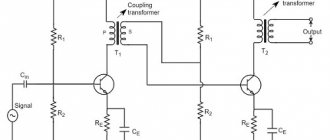
↑ So, there is a diagram:
Fragment excluded. The full version is available to patrons and full members of the community.
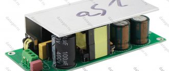
And the fee:
Fragment excluded. The full version is available to patrons and full members of the community.
In general, it’s nothing complicated, just recalculate the transformer and that’s it.
But when I sat down to do the calculations, I realized that the problem could not be solved head-on.
The calculation shows that there is only one secondary voltage, the current is fixed, and no load change is planned. I have at least two voltages, one adjustable, the second trailer. The power is also different. In general, according to calculations, the required number of turns of the primary turned out to be from 24 to 26.5, depending on the minimum operating frequency for a given transformer.
I did the calculations on a piece of paper, I was already ready to do the work, but I decided not to bother and just follow the calculated data for the resonant circuit. We'll deal with the tension later. Therefore, I wound it by analogy with the transformer from the previous description - more precisely from the datasheet, with adjustments to the secondary windings.
Namely:
Primary – 36 turns – litz 60×0.1 mm. Self-feeding – 3+3 turns – single-core 0.4 mm. Secondary – 6.3V – 1+1 turns – litz 85×0.1 mm Secondary – 250V – 40 turns – 0.4 mm single-core wire. The core is ER3542, sectioned into two sections.
Winding order: I wind the primary onto the “long” section. It turns out to be approximately 3.5 layers. Between the layers there is a spacer of adhesive tape. On top of the primary is a self-supply winding. On the “short” section I wind the anode, also with interlayer insulation, followed by the incandescence. Everything fits, the lid fits with a large gap.
Assembled and tried on:
Tight is normal!
Now the leakage inductance - it turns out to be higher here - since there are fewer turns on the secondary... Let's check it in operation...
All that remains is to select the gap and you can start. To organize the required inductance in this transformer, it turned out to be enough to lay a standard sheet of 80 g/m2 in one layer along the central core and on the sides.
Well? Are we starting? Naturally, the first switching on is through a light bulb!
Load - car lamp 12V 21+5W for filament, refrigerator lighting lamp 220V 15W for anode.
The launch was successful, unfortunately nothing exploded, the voltage is regulated, and so is the frequency.
Well, any fool can work on a refrigerator light bulb, and a car lamp is not a load. Let's load you up, shall we?
As a load, I decided to use “heavy” incandescent lamps, from those found in supplies - 6N13S. The filament current per cylinder is 2.8-3A, almost like four 6P3S. There are no problems with the anode, there are a bunch of 220V 40-60W light bulbs. That is, 100W of load is enough for the anode - even with a strong margin for an “average” home push-pull. I try to turn it on - start - and then stop!
The protection, which is indicated in the datasheet as OVP (Over-Voltage Protection), does not sleep and honestly fulfills its function! As I already said, when operating in resonant mode, the voltage increases proportionally on all windings of the transformer. Therefore, the self-power of the controller also increases.
Now I need to think about how to make the power supply pull the load I need without falling into OVP. Maybe I can wind the trance closer to my calculations? That is, reduce the number of turns in the primary? I unwind 6 turns from the primary. I bite off the tail, realizing that I won’t be able to wind it back. I'm collecting. The inductance decreased, it was necessary to remove the gaskets from the side parts of the magnetic circuit.
I'll try it with a light bulb. It started. I turn off the light bulb and turn it on directly. Silence! That is, there is not even a launch! Although the controller’s power supply is 15.4V – it’s normal for starting... I put the lamp back into the 220V circuit – there’s a start! What kind of nonsense is this?
At my own peril and risk, having placed minimal loads, I try to start with a short-circuited current protection. There is a launch! Strange... With a smaller number of turns of the primary, with a sharp increase in power, apparently there is a surge in the current circuit, which “locks out” the controller completely... And through the lamp there is a kind of “soft start” on the high side, and if there is any surge, then it is not sufficient to trigger the current. I haven’t found out why this happens, maybe the wiring of the PP has some effect... It’s interesting, but the device doesn’t have time to detect it, no matter how I tried... But the fact is a fact - if you short the current, everything works.
And this is not normal! This means we need to return everything back and then wind up the filament winding in order to get 6.3V under the required load, and not go beyond the OVP on self-supply.
I rewind the primary - now there are 36 turns again. And I use 2×1.5 turns for the filament. Since it is impossible to wind a whole number of turns for such a low voltage, we have to collectively farm the output of the midpoint to the top of the trance.
Launch with new data - everything starts - great!
Load - 6N13S lamp and a pair of lamps - 220V 15W and 220V 60W.
I poke another 6Н13С - and oops, OVP again! ...
Yes. For a small PP amplifier everything is fine. The total load is about 100W. But I need to understand where its limit is? When will the current trip not from the short circuit, but from the load? And so the current-measuring resistor already consists of two 0.33 Ohm resistors... Still, you will have to make a stabilizer to power the controller... And abandon OVP. For powerful solutions. Switchable stub, if necessary. Something like this…
Well, for now I’m hanging my nose... I don’t like breadboards and surface-mounted installations. But before making a new PCB, you need to check everything! Including the thermal regime of the stub. I'm using LM317. This stabilizer is easy to configure and quite reliable. It would be possible to hang a resistor and a zener diode, but this is for those who like to take risks. Especially with such a range of input voltages on the zener diode. There it is 15.6 at the start, and at 23.5 the power supply turns off - which means it can and will be clearly higher!
Why am I thinking about OVP? In principle, this is a useful feature. Unlike OLP (Overload Protection), which monitors current through power switches, OVP allows you to track problems in the OS. After all, if you turn off feedback, the controller will begin to reduce the frequency, which will cause an increase in voltage on all secondary devices. Is it good if the current “catch” it? And if not, the electrolytes will be the first to go and then with all the consequences...
But on the other hand, the datasheet circuit initially contains a stabilizer and OVP is needed only to protect the controller from overvoltage when powered from its own trance.
In general, I sculpt a knee stub at 17-18V and try it!
And this is happiness! :) The load is about 40W.
And then the load is 2×6N13C+ auto lamp, 220V 60W+40W+15W.
Now, at any load, the pulse range is the same, as can be seen in the blue oscillogram. Pay attention to the dependence of frequency on load - this is clearly visible here.
Well, and most importantly, I finally got the current to work! The fact is that the power supply starts up on cold lamps, and after a second it falls into defense. If you disconnect either the 40W lamp from the anode or remove one 6N13S, the start is normal. Then, after the lamps warm up - you can plug in anything on the go - it no longer turns off. This can be seen on the yellow line at maximum load - the swing approaches the calculated 0.6V for current protection to operate.
But it doesn't matter. The current resistance is set to 2×0.33 Ohm, which corresponds to a current of about 4A, at which the protection can operate. For modern field workers, this is not even a working current, let alone an emergency one. And it’s not so easy to “push” a cold lamp - this is the biggest problem.
And in a real circuit, even if you do not use a delay in the supply of the anode, the current will flow through the lamp only after the cathodes have warmed up, and therefore at the time of start the anode winding will only work on the filter capacity, and an emergency situation with an overload simply will not arise.
Well, if you want more, nothing prevents you from installing resistors of lower resistance. But if you really need it...
↑ Hollywood Happy End
Fragment excluded. The full version is available to patrons and full members of the community.
This circuit is built on the principle of separate power supply for the filament and anode circuits. This solution has a number of advantages; previously it was implemented on transformers of the “TN” and “TA” series, respectively.
First
.
The separation of “responsibilities” provides a good margin, since there is no need to include losses in the power as in the “reversal”, where two transformers are also indispensable, but they are used ineffectively. Second.
It is worth remembering that a transformer with a small amount of copper and steel, at rated load, emits noise that is different in intensity from a transformer in which copper and steel were not saved.
Therefore, the current reserve will not hurt. Third.
You can, without touching the anode supply, change the filament voltage from 6 to 12 Volts.
In the second case, if the device is hybrid, we can power the operational amplifier and filament from one circuit. Fourth.
Unlike a multiplier, a doubler has a better load characteristic, less ripple and a different spectrum. I deliberately did not build a tripler, quadrupler, etc. As the number of links increases, the internal resistance of the power source and losses increase. All this casts doubt on the feasibility of building multipliers. Maybe members of the forum, using my work, will build a block with other characteristics, it will be interesting! I needed 120 Volts at a current of 2 mA, and without background, the power supply coped with this task.
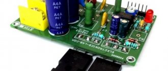
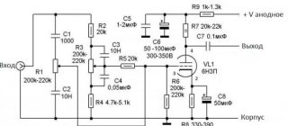
↑ So, the final scheme:
Fragment excluded. The full version is available to patrons and full members of the community.
Since when making changes to the wiring, the board was forced to increase in width, I decided to add a bias winding with a rectifier. What if it comes in handy when? The launch with the new board went without incident.
In general, everything is fine. I measured the pulsations under load at the anode and filament.
Blue - anode. Yellow – glow. What was surprising is that there is one conductor in the anode - a 1 uF 630V film - no electrolytes and the ripple is only 1V! Well, never mind, an electronic throttle will easily cure this!
The only thing that confuses us is the thermal regime of the filament rectifier diodes. For this purpose, I placed two dual STPS3045 in parallel. At 7A current, after 15 minutes it is no longer comfortable to hold your hand on the radiator. Well, that’s understandable, the voltage is already low, and it also drops by 0.5V on the diodes. For such a current, more than 3W per case is obtained. It is more profitable to power the filament from 12V and the lamp as a last resort, but this is of course a perversion. It’s better, if everything is really bad, to install a larger radiator.
But the power section breaks the pattern!
The radiators did not heat up. At all. It’s as if the power supply doesn’t work, but just lies on the table. Even the stabilizer radiator feels 35 degrees to the touch, and these are cold! The thought creeps in about the advisability of using radiators there in general. This is what soft switching means!
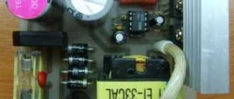
For the final test, I decided to bring the conditions as close to real as possible. I applied heat to 4×6P3S-E and 2×6N8S. I also assembled an electronic choke on my knee, it can be seen in the lower right corner, loading it onto 60W and 15W lamps in parallel. Anyway, after 20W the anode of the 6P3S starts to turn red.
I drove it for a bit until the paper began to smolder under the 60W lamp and smoke started pouring out. The power switches are cold, the Schottkis are heated up, but not so much, but the heating is stable, about 60 degrees. There was also a lamp shining directly on the radiator, and this seemed to distort the picture a little, but in general, the task was completed.
↑ Ways out of the situation
I will not consider well-known methods, since they are all well described on the “net”.
I will limit myself to a simple listing indicating the main pitfalls. Reverse switching on of the transformer, the so-called “reversal”.
The “step-up” transformer works inefficiently, the losses are high. The secondary winding, which has now become the primary winding, consumes a significant current, loading the first transformer, on which the glow is already “hanging”. However, the solution is common and quite acceptable.
Multiplier.
To obtain a low level of ripple, capacitors of significant capacity are required, as a result of which an increase in the “living area” of the power supply unit is required. The appearance of “uncharacteristic” contamination of the supply voltage, due to an increase in the number of transient processes, does not have the best effect on the sound. And, probably, the main drawback is the low load capacity of the power supply. At the same time, it is very difficult to accurately calculate how much the voltage will decrease under load and how much interference will increase. I never participate in debates on the topic: “Which Ohm’s Law is the most correct,” and therefore let me remind you that only cheese in a mousetrap is for nothing. In other words, by how many times you multiply the voltage, you will lose in current, plus losses, where without them.
Further presentation will take place using the example of building a power supply for a hybrid (op-amp + electron tube) Overdrive for a guitar. The principle can be used for any other devices, it is general. As a result, I got a floor-standing tube guitar preamp. At first I perceived it simply as a model and wanted to take it apart, but I liked it so much that I left it “alive.” For clarity, we will consider its power supply.
↑ Results and conclusions
Well, in conclusion, some impressions and conclusions about the work of the power supply.
As I already said, when the resonant circuit operates, the voltage changes on all windings. This is not fatal, but you need to pay attention, for example, to the operating voltage of the electrolytes. At startup, while the filaments are cold and the current through them is much higher than the rated value, the voltage on the anode winding can be 10-15 percent higher than the nominal value, and then smoothly, as the filaments warm up, decreases to normal. Naturally, it will be necessary to use a smooth supply of the anode, this is obvious for such a power supply arrangement.
Overload protection also works very well. Sometimes it is simply not clear why the block does not start, but the controller does not sleep and turns off before generation begins.
Therefore, there is no way to overload it with normally working protection. LLC resonance topology requires operation under load - then efficiency is maximum. Therefore, powering lamps with it is just a normal use. Only a long warm-up of the filament delays the start of the power supply in loaded mode, but this is not a problem, then everything returns to normal.
Class A, work on screen backlight drivers, ultra-bright diodes, any other active and constant load - these are the direct applications of this topology.
Among the shortcomings
– relative complexity of winding the transformer. Although, what prevents you from sectioning the coils yourself? I didn’t - I ordered ready-made ones. I haven’t tried winding the primary with a single-core wire - it’s still difficult to deceive the laws of physics, and it seems to me that the result will be predictably bad. Transformer inductance measurement is required. Without this, there’s no way – there’s no way to get into the desired range by eye. Although maybe someone will try.
Otherwise, I really liked it and can recommend repeating it!
I'm happily waiting for the delivery of FSFR2100 and FSFA2100, the latter, judging by the datasheet, is also interesting, but this is PWM.
↑ The essence of the problem
The prospect of winding a compact transformer for a tube device can cool the ardor of the most diligent radio amateur, and there are several reasons for this. A number of requirements are imposed on power transformers for lamp devices, which are not easy to comply with. A winding with good dielectric strength, capable of delivering relatively low current at high voltage, and a winding for powering the filament are required. The current consumed by the filament is usually in the range of 300-600 mA. First, you need to acquire a core with low overall power, and this first problem may become the last. But let’s assume that the core has been found and there is also a thin wire with good insulation. All the same, winding the transformer will be very difficult. Small cross-section wire must be handled delicately, avoiding kinks, much less damage to the insulation and breaks. The hardware window will not allow you to choose a thicker wire.
↑ PS
When the article was already written and posted on the portal, I asked myself a number of questions: “So what? What's next? On the shelf? For analysis?“ And yet I decided. We need to finish it to the end. And if normal people select a lamp, a circuit on it, and build power, transformers, and layout around it, then for me it all started from the other end. From food. I rummaged through the bins, found a couple of trances, and rewinded them with the remains of the wire.
RR. Gu-17+ ECC88. Ability to operate in ultralinear and pentode modes. Select mode using jumpers. The bias is fixed, since in the second version I added a bias winding.
The choice of lamps is not accidental. I needed to fit into “my” standard size in width and depth, so that it would fit into the rack and not bulge out in height. From what was there - 6E5P, 6P1P and Gu-17. The latter are more powerful - so they went into action. At the same time, I rewound the filament to 12.6V, this makes it easier for the diodes in a dense arrangement. 25W tube audio into 5 ohms with resonant power supply. At UL. There is more in the pentode. I think I've had enough.
The speakers are quiet. No disturbances or artifacts with the conversion frequency were noticed. Here's a practical application for you. The circuit is similar to that published in my article about an amplifier using TAN transformers. And most importantly, the goal has been achieved, the process has been completed successfully.
Well, that's all for now.