It just so happened historically that the apartment building in which I live, with two elevators, a bunch of light bulbs and other electrical appliances, has been powered for the past ten years using a temporary power supply scheme using a cable more than 200 meters long. In this regard, in the evenings, when the residents of the house are relaxing and receiving guests, when loads, such as an elevator, are turned on, the voltage in the network drops quite noticeably. In the sound of my single-ended tube amplifier, this appears as a brief (a few seconds) appearance of AC hum. The electronic power filter I used, also called an “electronic choke,” does not help in this case. I think it will be useful to understand what is happening and what to do.
Anode voltage stabilizer. Diagram and description
When assembling tube-based devices, we regularly encounter significant differences between the output voltage of the anode power supply and the actual requirements of the circuit.
Eliminating scatter using a series-connected resistor has a number of disadvantages, including voltage sag from the load. The circuit presented in this article is able to provide the required voltage with a deviation of 4-5% with reduced ripple. Below is a diagram of an anode voltage stabilizer.
Diode VD1 at the input protects the circuit from polarity reversal. Zener diodes VD2, VD3 and resistor R1 create a reference voltage. Accordingly, by selecting these elements, we set the output voltage we need.
The reference voltage is supplied to the gate of transistors VT1 and VT2. The use of MOSFET transistors instead of bipolar transistors is dictated by the absence in them of the phenomenon of secondary breakdown, which limits the flow of current at high voltages. The use of two transistors promotes better heat dissipation from them.
Resistor R2 and capacitor C2 prevent the occurrence of parasitic oscillations. Resistors R3 and R4 are designed to eliminate differences in the characteristics of transistors VT1 and VT2. Resistors R5 and R6 and transistor VT3 limit the output current to a specified value.
If the voltage drop across R6 is large enough, transistor VT3 opens, causing the source of transistors VT1 and VT2 to close with their gates. This reduces the output voltage and conserves load current. Resistor R5 protects the base of transistor VT3 from damage by high current. Capacitors C1 and C3 are designed to eliminate impulse noise, which is extremely undesirable in tube circuits.
The anode voltage stabilizer is assembled on a single-sided printed circuit board measuring 105 mm by 40 mm. The printed circuit board for the Eagle program can be downloaded at the end of the article.
If the stabilizer is intended for a small load (up to 20 W), then you can refuse to connect the transistor VT2 and resistor R4. Before installing resistors R1 and R6, you should calculate their resistance from Ohm’s law:
- Uin – stabilizer input voltage, (V)
- Uz – sum of voltages of zener diodes D1 and D2, (V)
- Imax - maximum output current, (A)
For proper operation of zener diodes, a current of at least 5 mA is required. The possible maximum output voltage is limited by the drain-source voltage of transistors VT1 and VT2, the operating voltage of capacitors C1...C3 and the strength of connectors CON1 and CON2.
Its value is determined by summing the voltages of the zener diodes VD2 and VD3, and it is not recommended to raise more than 300 volts, since this is quite enough for a preamplifier and other low-power circuits. Zener diodes should be mounted slightly above the board due to the heat generated. It is advisable to select zener diodes with the highest possible power so that overheating can be avoided.
For output current exceeding 150 mA, resistors R3, R4 and R6 must be of higher power. The actual values of the output voltage and maximum current obtained may differ from the calculated ones due to tolerances of the parameters of individual elements.
This circuit is designed for a supply voltage of approximately 260 V, with an output voltage of approximately 220 V (200 V + 24 V zener diodes in series) and a maximum output current of approximately 70 mA.
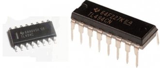
Transistors VT1 and VT2 must be the same. Their type can be any, however, they must meet the minimum requirements in terms of parameters: a MOSFET transistor with an N-type channel and a maximum drain-source voltage of at least 500 V. For example, the IRF820 transistor meets these requirements.
Download PCB drawing (3.6 KiB, downloads: 1,295)
Source
↑ The essence of the problem
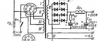
You should start by analyzing the electronic filter circuit and the processes that occur in this circuit when the supply voltage changes. A typical circuit of an electronic filter and network simulator is shown in Fig. 1 .
Rice.
1 Briefly about the operation of the circuit: - Elements R4 and C2 determine the rate of rise of the output voltage and, with the values indicated in the diagram, the rise time is T = 23 sec; — Resistors R2 and R3 form a voltage divider that sets the operating point of transistor VT1. The choice of this operating point is made from the condition that the instantaneous voltage at the drain of transistor VT1, at no value of the supply voltage, should be less than the voltage at the gate of transistor VT1. And since in the steady state of operation of the circuit, the current flowing through resistors R4 and R5 is negligible and, in practice, is determined only by the leakage current of capacitor C2, the voltage at the gate is equal to the voltage at the connection point of R2 and R3.
Why is that?
Yes, because when the voltage at the drain is less than the voltage at the gate by the value of the saturation voltage of the field-effect transistor, this transistor goes into the saturated switch state and ceases to perform the function of a source follower. The load voltage becomes equal to the filter input voltage. The filter disappears, as if it never existed, until either the input voltage increases or until capacitor C2 is discharged through resistor R4 in a time of T = 23 seconds.
Theoretically, it is possible to determine the minimum value of the network voltage based on the requirements of GOST 13109-97 “Electric energy quality standards in general-purpose power supply systems.” This GOST uses the concepts of “voltage deviation” as a slow, over a day or more, change in network voltage from the nominal value and “voltage fluctuations”, defined, as I understand it, as the number of voltage fluctuations over a certain time interval with a duration, as a rule, less than 1 minute. It is indicated that the maximum voltage deviation from the nominal value can reach ± 10%, and voltage fluctuations are also possible, the magnitude of which can also reach values of up to 10% of the nominal value. Probably, energy specialists know the subject better, and if I’m wrong, one of them will correct me. Until then, we will consider this as initial data, namely: taking into account the permissible deviation, the voltage in the network can be 198 - 244 V, and, taking into account also permissible fluctuations, the voltage in the network can be in the range of 176-264 Volts
.
I think it's HORRIBLE!!! But GOST allows this.
Anode power supply for tube amplifiers
Formulation of the problem
I prefer to stabilize the anodic rather than auto-bias with “our” electrolytes. To power the anode of lamps, you usually need a stable, adjustable constant (especially for loftin) = 300-400 V, 150-220 V with currents (without fanaticism) up to 20 and 350-400 mA. About air heaters - this is not here. A minimum of details - not exotic. And so that all this works stably, and does not burn the lamps by exceeding the current consumption. And, perhaps, the most important thing is that even a pensioner can afford it (sometimes).
Reining in Needs
Calculate the currents of your circuit and accept the power factor of the power supply as no more than x2, this will be enough.
Selection of parts and diagrams. Fortunately, GOOGLE gives unlimited (reasonable) limits... to the flight of fancy of the authors, don’t stumble upon the Moses - may the confessions forgive me. I recommend studying it as a basis.
Translation for those who don’t want to read = we get decent stabilization of the fixed voltage up to a reasonable 450-500 V, above that it will break through the insulation, with uncontrolled maximum currents depending on the transformer + fuse insert + rectifier diodes + radiator for the field worker and the diameter of the core of your home protection / wiring alternating 220 V.
Scratching the back of my head, which was leaving behind gray hair, I made a decision (may the author forgive me):
- abandon the idea of a step change in the output voltage by substituting zener diodes into the cathode (3) SE;
- introduce the possibility of some adjustment of the voltage output;
- introduce current limitation/protection (smoothly adjustable) = see “Problem Statement”.
Composition of the device
- transformer;
- protection against overcurrent (short circuit) and inrush current due to alternating current (such as varistor R1 and fuse link FU1);
- rectifier (preferably with fast diodes);
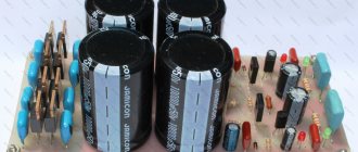
- smoothing C1 (about 4 µF per 1 Watt of power, otherwise the large capacitance at the moment of switching on “shorts” + the diode bridge to the body with all the consequences...);
- VT1 key on a powerful field switch (with 12 V gate-source protection);
- controller/amplifier (mosfet control) error DA1 – output voltage;
- smoothly adjustable current limiter on VT2, R3,4;
- OS voltage divider R5-6-7.
Here's what happened, without the calculated denominations yet:
Datasheet on SE for calculations:
“Internals” of SE for understanding:
This means (already marked on the diagram):
- for normal operation of the SE series 012-040, the anode-cathode voltage (VCGO) must be 50 V, for the rest 070-140 = 150 V;
- in this case, the current consumption (Ic) is exactly 20 mA, this is all for calculating R2;
- OS divider current R5,6,7 is about 2 mA for heater reasons;
- “current limiting” voltage = VT2 response about 0.7 V = this is for calculating R3;
- The “normal-operating” voltage drop (the difference between the input and output for the field device) should be more than 8 V, its excess, multiplied by the device current, is the heating of the field device.
Arithmetic (primary school)
EXAMPLE 1:
Output needed = 144 V no more than 20 mA, input 155 V (such a transformer). I have SE103N.
R2 = (input 155 V – operating SE 150 V)/current SE 0.02 A = 250 Ohm, power on it = 5x0.02 = 0.1.
R5+R6+R7 = output 144 V/divider current 0.002 = 72 kOhm.
R7 + 1/2R6 = operating SE 103 V/divider current 0.002 = 51.5 kOhm, let’s take the adjustment % to be about 10, which means 72x10% = 7.2 kOhm.
R7 = 51.5 – 7.2 = 44.3 kOhm = 43 kOhm.
R6 about 10-12 kOhm.
R5 remains 72-43-12 = 17 kOhm = 18 kOhm, power on all R5, R6, R7 = 144x0.002 = 0.288 W.
R3 = VT2 threshold 0.7 V/limit 0.02 A = 35 Ohm (it is necessary to take into account the rating of R4), this means with such a resistance (R4 slider to the left = Uke = maximum) the device will limit the current to 20 mA, slider to the right - less "resistance/voltage" = more current needed to limit = increased limiting current.
EXAMPLE 2:
The output is needed 215 V no more than 350 mA, the input is 250 V, there is SE 130. Just numbers, for simplicity and to eliminate errors I print out the bare circuit + sign GIVEN and press the buttons on the slide rule.
R2 = (250-150)/0.02 = 5000, power = (250-150)x0.02 = 2 W.
R5, R6, R7 = 215/0.002 = 107500
R7 + 1/2R6 = 130/0.002 = 65000
R6 = 65000×10% = 6500
R5 = 107500 – 65000 – 6500 = 36000
Power R5, R6, R7 = 215×0.002 = 0.43 W
R3 = 0.7/0.35 = 2 Ohm
IMPORTANT! Measure the voltage drop across the field switch and multiply it by the current you need = don’t forget about a small radiator. Further explanation I consider “chewing fingers” as my mentor said
Tested, it works! There may be typos, thanks for the correction. Good luck to all.
Source
Tube amps are not bad. Let's add some common sense, part 5
Continuation of the article based on materials from the Internet electronic network with reflections from Yuri Ignatenko’s “Notebook” , as well as my comments and amendments
Rectifier diodes
Below are pictures with the results of the laboratory work. These results allow us to close the topic of interference allegedly created by diodes.
As you can see from the pictures, there is no interference. There are no impulses that are terribly convincingly described on websites. That they say the interference extends hundreds of kHz up the range from 50Hz. If the diode really created interference, then radio receivers and transceivers with a sensitivity of 0.5-1 μV would make noise and whistle. And reception would be extremely difficult. Therefore, confidently use silicon diodes in power supply rectifiers for ULF. CC diode assemblies are very convenient; place them where you want and how you want. This does not affect the sound.
Kenotron. Question. Tell me, is there a difference between a kenotron and diodes, other than a slower supply of power to the lamps and a voltage drop across the kenotron?
Answer. The kenotron is an outdated age. But “audiophiles” hear how it sounds. They hear a lot of things. The fact is that there is a marketing component to the answer to this question. For a person who is convinced of delusion, a kenotron can be used for some money. Exoticism is a matter of taste. In addition, an increased amount of hot glass in a technical project often evokes positive emotions, especially when it is done tastefully. It’s beautiful and you can warm up from the increased heat generation.
The harsh reality is that I don’t hear the kenotrons, my friends don’t hear. And having wiretapped the “audiophiles” in the dark, I realized that they couldn’t hear either. We could never guess the interstage capacitor. Neither the speaker cable. An absolutely accurate result was obtained, called: a finger in the sky. We didn’t guess when with a kenotron, when with diodes.
Question. How real, in your opinion, is the threat, which is written about in almost every book, of a decrease in the reliability of the lamp in the event of a sudden supply of anode voltage with cold cathodes, every time it is turned on? Especially relevant when you recommend such a high (in my opinion) anode voltage of 340V? Although almost all serial receivers after 57-59 already came with semiconductor anode voltage rectifiers? The threat of supplying a cold anode seemed to have been “neglected”?
Answer. They did the right thing, everything had its time. Progress led to the creation of ABC80 selenium rectifiers. ABC120ma. Then there were germanium diodes and finally silicon D226B. And old receivers and televisions with diode bridges worked. The lamps were heated in them for 10 years until they turned black. Actually, the devil is not as scary as he is painted. After all, no one measured the effectiveness of using old lamp technology in shaggy prehistoric times or counted how many lamps broke down at what time. People lived in a simpler way in those days; human life was worth nothing. All reliability reserves were provided by GOST standards and “Glory to the CPSU”. The operation of modern lamp equipment in extreme conditions requires caution and attention from a person. An elementary sense of responsibility for the written lines obliges us to warn every television viewer about the dangers of high voltage. When it comes to officials, it is very easy for them to go to jail for an accident with injured or dead people. I think that such an argument will bring some sense to anyone.
If you really want to take care of the lamps, you can install an “anode” toggle switch. In this case, the toggle switch contacts are bridged with a 100 kOhm resistor. After turning on the glow, the rectifier electrolytes will slowly begin to charge. After a minute, you can turn on the anode voltage. Kenotrons are installed by audiophiles who do not listen to music, but listen to how the kenotron sounds. It is extremely important for a paranoid person to know what a capacitor or normalizer wire sounds like when irradiated at an accelerator in Dubna with a beam of high-energy electrons. The word threat should not be used in this context. But a reasonable person always has a fear of lamp failure. However, as well as the fear of being left without eyes in the event of an explosion of lamp hardware. You need to remember that human life and health are an invaluable gift for a specific person. Therefore, just throw any bravado and mischief in high-voltage lamp technology into the trash. And any author who writes the opposite is simply a mossy idiot. If you enjoy regularly flicking the switch, knowing that 800 volts is coming to the anode at this time, then the flag is in your hands and the adrenaline is in your brain. And if age, experience or mental characteristics warn you, then you can entrust this task to a relay that works with a time delay and live more comfortably.
Question. So do you still need to install a toggle switch to turn on the “anode” power supply or not?
Answer. It is necessary to distinguish between show-off and common sense. Therefore, everyone solves the problem with toggle switches and delays independently. Old lamp technology never had anode delays or anode toggle switches, and TVs worked for 10-15 years without replacing lamps. “Anode” toggle switches were found in military communications equipment. The equipment, which was in standby mode, with the heat switched on, was supposed to enter into communication at any moment, without a warm-up delay. Tube amplifier layouts can apparently be done directly. And regularly operated high-voltage equipment, especially those operating in extreme conditions, can be made more careful. Look back at yourself. As a pedestrian, you don't always walk on the green. You often run into red lights. To make the example clearer, change the level of your own responsibility, get behind the wheel and try to pass the same traffic light with the same frequency. Sooner or later, the most stubborn person will receive the required answer on his own.
The kenotron and diode bridge work the same way. The myth is that the kenotron takes longer to warm up and supplies the anode to the lamps when they have already warmed up. The kenotron warms up in just 2-4 seconds and already supplies voltage. And the output lamps warm up for 30 seconds and begin to take current. Below are pictures from the recorder, which show the measured transients in the kenotron rectifier. As you can see, after 2 seconds, the anode voltage began to increase. What kind of delay could there be? The lower scale is divided into seconds from the moment of switching on. The red line shows the increase in voltage after turning on the amplifier on the first electrolyte of the filter.
Power transformer
The power transformer can be used from any tube receiver or TV. Provided that the anode voltage and current after the inductor under load will be at least 310 volts and 120 - 240 mA (120 mA for a single-cycle stereo, 240 mA for a two-cycle stereo on weekends 6P6S, 6P3S, 6P14P). If 240-260 volts then distortion will be at increased volume. Since the ULF power is only 2 watts, the amplifier goes into limitation. There will be no dynamics, transparency and depth. There will be a normal sound like from a radio.
When you increase the anode voltage to 300-320 volts everything will be fine. I already wrote to you that 300 volts at the anode is no less (the voltage at the anode is measured relative to the cathode). Power supply 320-340 volts. Only then does the SOI drop and the power increases. And the anode has not yet become hot in any lamp. And not a single lamp failed. I don’t use less than 300 volts. You should start with at least the original vehicle that has not been rewound. Then TVK -110 can be installed and this will increase the anode voltage to 300 volts without rewinding the vehicle. When you rewind the silovik, always make a couple of taps at the end, 50 and 100 turns. To select the anode more precisely.
You'll never guess what the tension will be. This depends on the resistance of the anode winding, load, and inductor resistance. Two half-wave rectifier. 305 x 1.41 = 425 volts on the first capacitor without load. You will find out what will happen to the load on the second filter capacitor when you connect everything. It's not hard to make bends when you're shaking. And then just select.
Question. Is one power transformer from TV Record-67 enough for a 6p14p push-pull circuit for two channels?
Answer. No, not enough. It is designed for one single-cycle ULF. The main current is taken by the output lamps or amplifier lamp. The preliminary stage and the receiving path lamps consume insignificant current. Therefore, 4 output lamps whose total current consumption will be 180mA and + the remaining lamps 10mA require a 200-220mA rectifier for two channels. You can find the data on the secondary winding of this power transformer and estimate. The diameter of the wire is simply considered to be 0.7 X root of I. For example, a current of 0.25 a is required. Square root from 0.25 = 0.5 Multiply by 0.7 = 0.35 the wire must be in the winding. The diameter of the wire of any transformer winding can be determined by the formula: d = 0.8 x root of I = d equals 0.8 times the root of the current. (if the trans is large, you can take 0.7 multiplied by the root of the current). where I is the current strength (A) passing through this winding; d is the diameter of the wire (copper) in mm.
Question. Is one power transformer from Rigonda 102 enough for a push-pull stereo amplifier, since there were several more tubes in the radio that we don’t use?
Answer. In the receiver, the ULF always consumes the most current of all stages. And in a high-quality ULF operating in pure class A, we also increase the operating current of the output lamps. Therefore, it is incorrect to assume that the secondary current is enough. The factory designed 1 power transformer for 1 channel, which means it must be installed on one. At the factory they counted back to back. The formula for determining the wire diameter from the current consumed is known. 0.8 square root from the current consumed. The current consumed will be 110mA for each amplifier. 0.22a two channels. Taking into account the conversion of alternating voltage to direct (1.2) 0.265a winding current. 0.53x0.8=0.46 secondary diameter is needed to power two channels from one transformer. And we have a secondary diameter of only 0.29 mm, which is why the silovik from Rigonda 102 push-pull stereo amplifier will not handle it. For example, the silovik from Symphony Stereo has a secondary with a diameter of 0.44 mm and a larger iron cross-section. Here he will pull two push-pull channels on 6P14P. Therefore, for a push-pull stereo amplifier, you will need two power transformers from Rigonda 102.
Question. Is it possible to use one power switch for two channels? Is it possible for a signal from an adjacent channel to penetrate through the power circuits?
Answer. One security officer can be used. If the electrolyte capacity is sufficient and there are two chokes, one per channel, then the separation will be excellent and there will be no signal penetration. It will be more accurate, but at a level of -80 -100dB, and this is not -30dB like with American vintage amplifiers. But in those days they did not strive for good channel separation, because the best media was vinyl and the best head only had 25dB channel separation. And now CDs and Flakes have 60 - 90dB channel separation.
Question. How to determine the power of a vehicle based on the cross-section of the core?
Answer. By power transformer. Approximately the cross section of the core in a square gives power. 10cm.sq. = 100W. 8cm.sq. =64W. Or you can look it up in the directory.
Question. I have two filament windings. What is the best way to divide the heat - through cascades or channels?
Answer. It is desirable to have output stages from one winding and one output to ground. Pre-stages are fed from another winding and make a virtual midpoint. Two resistors of identical 100-300 Ohms are soldered to the filament winding and the connection of the two resistors is to ground. There will be no background.
Question. If all the amplifier tubes are connected to one filament winding of the transformer (the cross-section of the wire allows it), will this affect the sound quality?
Answer. No it won't affect it. Just make the middle point with two resistances of 100-300 Ohms.
Question. Is it possible to use a half-wave rectifier with voltage doubling?
Answer. If you have a transformer with a secondary voltage of 130-150 volts and a winding current of 300-500 mA, you can make such rectifiers. Or a lamp, let’s say, you have a G807 or GU50 at the output - they are high-voltage and your trans with 250 volts can be turned on according to this circuit and get 600 volts of anode voltage.
Question. What current should the secondary be rated for if it is connected to a rectifier with doubling the voltage? You need 145 volts of alternating power for a two-stroke monoblock on 6P41S. What should we do with the secondary wire? The current through two 6P41S is about 140-150mA. should the cross-section of the power trans secondary wire be selected based on the calculation of 0.15 mA or 0.3A? I think it's under 0.3. I am now winding the anode trans with a wire of about 0.4 mm.
Answer. I order 145 volt 0.4a from TOR; 25v 0.1a; 6.5v 0.8a;6.5v 3.6a. Sometimes I use two universal TS, one for monoblocks and two-stroke units and the other for single-stroke units.
I make all push-pull amplifiers using 6P41C only as monoblocks (valve current is 70-80mA) and never use 6N8S. I already wrote that with 6N8S and OOOS there is not enough gain. And without entering OOOS, you cannot get excellent bass and drum beat. There will be a blurry sound.
I make full push-pull stereo amplifiers only on 6P3S and 6N9S and install these TS. One TS for 4 6P3S and two 6N9S lamps. This unit threshes all day without overheating. For 6P3S at 250 volts 60 mA current. At 300 volts 50mA at 330 - 350 volts 40-45mA.
Question. What to do if a power transformer covered with a casing is humming?
Answer. Until you focus your attention on the hum of the power transformer, you usually cannot hear it. Having installed the trans on an iron chassis, they attach a resonator and panel to it. The chassis increases the hum. Covering the trans with an iron cap also increases the buzz. Apparently the magnetic stray field interacts with the cap and causes additional vibrations of the walls and lid. We have to cover the insides of the caps with tape to reduce the vibration of the walls. You can apply car noise insulation.
Question. How to make power transformers quiet? I have two TS-180 (from a black and white TV) - both hum.
Answer. There is some experience in using TC180. Most of them usually buzz. You can show recommendations on how to fix this. You need to apply dipping the iron into liquid oil paint for a week. Using paint, the plates are tightened with clamps, two clamps for each iron horseshoe. Dry in the sun for a week. When ready, without removing the clamps, clean the ends by placing sandpaper on the glass and rubbing the ends for half an hour. The filament windings are wound three turns on each coil. Then two horseshoes are inserted into the coils. Dropping glue onto the ends, quickly insert two other horseshoes and tighten the trans with the original fastener. When ready, they are connected to the network by connecting the primary devices in series at 240-250 volts of voltage. The transformer will stop humming. And the current XX decreases. But this is labor-intensive and a long rigmarole. You need equipment, conditions and ventilation. To put it simply, you can switch the primary of the TC180 and TC270 to 254 volts. Then the current XX is minimal and the transformer does not hum. The incandescent ones are wound in 3 turns each, without disassembling the transformer. To reduce the hum of the transformer, it can be installed on the chassis through rubber gaskets, and a vinyl chloride bushing can be placed on the bolts. If the transformer does not hum, then there is no need for bushings and gaskets. If there is a buzzing trance, then you can put it like in the picture below.
Question. I finished up the TS 180, there is voltage, it doesn’t heat up, but it makes a very loud noise. Already took it apart and tightened it up. Before this, it didn’t buzz and wasn’t too tight, i.e. The nuts came off easily. I placed the horseshoes the same way they stood. What to do?
Answer. The winding in the TC 180 secondary is wound with a thick wire and allows you to make a rectifier with doubling. 40+60+40 volts = 140 volts. With doubling, you get 330 volts of anode under load. And there will also be a winding left for a fixed bias. 60+60+40 = 160 volts and with doubling you get 360 - 380 volts. Until you take it apart, it doesn’t hum, you yourself wrote about it. Therefore, it is impossible to disassemble it. Use the network connection completely. Connect two turns to the filament windings without disassembling the vehicle and you will be happy.
Note. For the general reader it is worth adding a short comment. The fact is that the use of transformers of the TC series is an extremely low-cost option for constructing a power source for an amplifier (practically for the poor). People who value their own time in the slightest degree should be wary of using TS transformers. And the quality of their manufacture and vibration-noise characteristics and large self-dissipation make them practically unsuitable for tube amplifiers. Nuggets have to spend enormous efforts to put the vehicle in order. Is this necessary? Other standard transformers, TA, TAN, TN series, are equally available. Don't waste time rewinding. Use TESTED green monolithic transformers. They have a wide selection of windings with supply voltages. Moreover, transformers designed for 127/220 volts should be used. The power transformer must be connected to the 220 volt network of the amplifier at the full voltage of the primary winding, i.e. use 127 volt terminals to further reduce the no-load current. In addition, transformers TA, TAN, TN must be carefully selected for lower no-load current. Then the problems of static interference and background noise in the amplifier, if other recommendations are followed, will be minimized. And bandage therapy is suitable for young people who have their whole lives ahead of them. It is better for mature men not to waste this time. This is especially true for building power supplies, for which everything has long been invented. It’s even better to get away from 50Hz transformers in the UMZCH power supply and use a pulsed source, for the construction of which there are simple and effective circuit solutions. Output transformers are more demanding. However, here too, skeining procedures should be carried out only as a last resort. And at the beginning of the journey of amplifier construction, the same standard transformers of the TN, TAN, TPP, TP, TTP, etc. series should be used as outputs. Evgeniy Bortnik
To be continued.
Evgeniy Bortnik, August 2015, Russia, Krasnoyarsk
7.1. Lamp reactive elements
Until now, we have not taken into account the influence on the properties of cascades of reactive elements of lamps, now it’s time to pay attention to them. We will show this with a practical example.
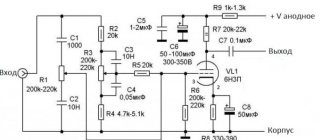
Let's consider an elementary triode amplification stage on 6N3P. Load resistance RA = 10 kOhm, slope at operating point S = 3 mA/V, µ= 36, Ri = 12 kOhm. Equivalent load. KU = 3·5.5 = 16.
However, there are still some things left out. The lamp has noticeable interelectrode capacitances. So for 6N3P:
SVH = 2.45 pF, OUT = 1.35 pF, SPR = 1.6 pF.
These are the capacitances of the lamp itself; in a real circuit, the capacitances of the installation and mating circuits are always added to them.
Modified device models
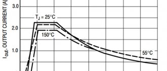
The maximum load current of this type is perceived up to 4 A. The input voltage by the capacitor can be processed to a level of no more than 15 V. The input current parameter for them usually does not exceed 5 A. In this case, the ripple is allowed to be minimal with an amplitude in the network of no more than 50 mV. The frequency can be maintained at 4 Hz. All this will ultimately have a positive effect on the overall efficiency.
Modern models of stabilizers of the above type cope with a load of around 3 A. Another distinctive feature of this modification is the fast conversion process. This is largely due to the use of powerful transistors that operate with through current. As a result, it becomes possible to stabilize the output signal. A switching type diode is additionally used at the output. It is installed in the system near the voltage node. Heating losses are significantly reduced, and this is a clear advantage of stabilizers of this type.
"COMMUNICATION FORWARD"
I have developed an open loop . I believe that it meets my requirements, and after test listening, I replaced standard feedback stabilizers in my designs, despite their high parameters.
In my topology, a stable reference voltage is first obtained, which is supplied through a buffer to a storage device (capacitor). The buffer ensures the constant output resistance of the stabilizer, and the capacitor ensures instantaneous energy supply to the amplifier during sharp fluctuations in the load current.
I simulated both topologies to test my reasoning.
It turned out that the feedback topology has a slightly higher stabilization coefficient and lower output impedance, which increases with increasing frequency.
However, based on the listening results, I preferred the topology without feedback .
Voltage stabilizer for filament circuits.
The buffer element of the stabilizer can be either a bipolar or field-effect transistor. In practice, I used field effect transistors with high transconductance, rated power and high operating voltage. Reliability was excellent!
A heat sink for the buffer transistor is required for both low-voltage and high-voltage regulators.
The capacitor in the TL431 circuit further reduces the noise level.
click to zoom
A disadvantage of the circuit can be considered the need to adjust the output voltage when replacing lamps, since due to design features, the consumption in the incandescent circuits differs for different lamps.
But that won’t stop a real audiophile!
AC voltage rectification
Today, the requirements for the quality of network voltage are quite lenient. Add to this the huge number of consumers with switching power supplies (computers, TVs, printers, DVD players, etc.) and the nonlinear characteristics of step-down transformers. As a result, the shape of the supply voltage is far from sine. First of all, a flattening of the tops of the half-waves is observed.
The figure shows the results of measuring the voltage at the output of the Ш-shaped transformer:
Click to enlarge
I was surprised, to be honest, I expected the worst.
Note from the editor-in-chief of RadioGazeta : keep in mind that the author lives in the UK!!! In the Russian power grid the picture will not be so rosy.
I use W-shaped transformers because I like their sound better. They are not as fast as tori, but I find they provide better detail and detail in the sound.
The previous figure also shows the output voltage spectrum of the bridge rectifier .
Terrible! Even worse than at the transformer input. Now harmonics with a frequency of 2 kHz have appeared, with a level of about 60 dB relative to the 50 Hz voltage ripple.
12.5. Triodes with sparse grid
However, you can retain the useful grain of the previous idea if you simply transform the problem on a large scale: at more familiar voltage levels, compress the anode characteristics of the lamps to the left. Then we come to a special type of triode.
This class of triodes, due to the sparse winding of the grid, is characterized by a very low µ value (from 2 to 5) and a proportionally low internal resistance of tens to hundreds of Ohms. The figure shows the characteristics of one of the triodes of this class - 6S19P. With a load line corresponding to 4.75 kOhm and an anode supply of 250 V, the residual voltage, as we see, is very low: approximately 40 volts.
In addition to high efficiency, a very low output impedance of the amplifier is achieved here, which is another plus. And operation at an equivalent load many times greater than Ri ensures high linearity.
But there is also a drawback: small µ requires the supply of a large amplitude of oscillations to the grid. The characteristics show that to drive the 6S19P lamp you will need about 100 V. Again, difficulties with the driver: it must be able to produce undistorted oscillations of a very high level.
The triodes in question were originally produced for electronic stabilizers (where the same problem exists: passing a large current with a small voltage drop). However, a number of types of lamps have found their real recognition precisely in their use for audio amplifiers: these are the domestic 6C4C and the foreign 300V, which has now gained particular popularity.
↑ Thoughts on using an electronic throttle
What conclusions can be drawn from this in relation to the “electronic throttle”?
1) The “electronic choke” cannot maintain the output voltage at a certain level; it repeats, with its own time constant, the input voltage. 2) For an “electronic choke”, the deviation of the voltage from the nominal one is not significant because a slow change in the mains voltage does not lead to a situation where the filter transistor goes into saturation. In this case, constant power is released at the transistor, independent of the supply voltage. 3) “Electronic throttle” copes well with the situation when the network voltage fluctuates upward. 4) The voltage divider of the “electronic choke” must have a transmission coefficient of no more than 0.9 plus a gate-to-source voltage drop (from 2 to 5 Volts) for normal operation of the transistor in source follower mode. As a consequence, in my opinion, the use of an “electronic choke” in circuits with low voltages of the order of 30 V is energetically unprofitable, since taking into account the same gate-source voltage drop (up to 5 V) leads to the fact that it is necessary to provide The voltage drop is quite large, up to 30% of the circuit supply voltage, and, at high operating currents, a good heat sink is indispensable. As a result, the simplicity of the circuit design (3 resistors, a capacitor and a transistor) is leveled out and replacing it with a voltage stabilizer (maybe even with the ability to adjust) seems like a justified step.
10.6. External load
When dealing with driver circuits, you should never forget that the load is not just the one at the anode. In parallel to it, the input of the next stage almost always operates, at least in the form of a grid leakage resistance connected through a capacitor. However, the load resistance may turn out to be quite small - for example, if the final stage operates with grid currents.
The presence of an external load will naturally reduce the output voltage, and at the same time the operating range of output voltages.
Let us assume that a calculation is first carried out at “idle speed”, as a result of which the maximum amplitude value uAmax at the anode is obtained. When taking into account the external load RH, both the gain and the maximum amplitude will decrease in proportion to the ratio between RA and RARH/(RA + RH). No amount of increasing the input signal will increase the output signal: it will begin to be limited. However, the connection of an external load itself will not affect the signal distortion in the pentode, since it will not change the anode-grid characteristics.
However, for a triode the situation is completely different.
Transistor stabilizers
In the 1st picture there is a circuit based on the 2SC1061 transistor.
The output of the device receives 12 volts; the output voltage depends directly on the voltage of the zener diode. The maximum permissible current is 1 ampere.
When using a 2N 3055 transistor, the maximum permissible output current can be increased to 2 amperes. In the 2nd figure there is a circuit of a stabilizer based on a 2N 3055 transistor; the output voltage, as in Figure 1, depends on the voltage of the zener diode.
- 6 V - output voltage, R1=330, VD=6.6 volts
- 7.5 V - output voltage, R1=270, VD = 8.2 volts
- 9 V - output voltage, R1=180, Vd=10
In the 3rd picture - an adapter for a car - the battery voltage in the car is 12 V. To create a voltage of a lower value, the following circuit is used.
Voltage stabilizer connection diagram
Watch this video on YouTube
Negative voltage stabilizer
It is clear that for negative voltage polarity the circuit must undergo changes, since there is no complementary analogue for the TL431 chip.
However, I also used the TL431, but in conjunction with a composite transistor (Darlington):
This stabilizer is usually used to power auxiliary circuits, for example, cathode sources of stable current. Therefore, exemplary parameters are not needed here and I did not complicate the circuit.
DIY adjustable power supply
A power supply is a necessary thing for every radio amateur, because to power electronic homemade products you need a regulated power source with a stabilized output voltage from 1.2 to 30 volts and a current of up to 10A, as well as built-in short circuit protection. The circuit shown in this figure is built from the minimum number of available and inexpensive parts.
Scheme of an regulated power supply on an LM317 stabilizer with short-circuit protection
The LM317 IC is an adjustable voltage regulator with built-in short circuit protection. The LM317 voltage stabilizer is designed for a current of no more than 1.5A, so a powerful MJE13009 transistor is added to the circuit, capable of passing through itself a really high current of up to 10A, according to the datasheet, a maximum of 12A. When you rotate the knob of the variable resistor P1 by 5K, the voltage at the output of the power supply changes.
There are also two shunt resistors R1 and R2 with a resistance of 200 Ohms, through which the microcircuit determines the output voltage and compares it with the input voltage. 10K resistor R3 discharges capacitor C1 after the power supply is turned off. The circuit is powered by voltage from 12 to 35 volts. The current strength will depend on the power of the transformer or switching power supply.
I drew this diagram at the request of novice radio amateurs who assemble circuits using wall-mounted installations.
Scheme of an regulated power supply with short-circuit protection on LM317
It is advisable to carry out the assembly on a printed circuit board, so it will be beautiful and neat.
Printed circuit board of the regulated power supply on the LM317 voltage regulator
The printed circuit board is made for imported transistors, so if you need to install a Soviet one, the transistor will have to be unfolded and connected with wires. The MJE13009 transistor can be replaced with the MJE13007 from the Soviet KT805, KT808, KT819 and other npn structure transistors, it all depends on the current you need. It is advisable to reinforce the power paths of the printed circuit board with solder or thin copper wire. The LM317 voltage stabilizer and the transistor must be installed on a radiator with sufficient area for cooling; a good option is, of course, a radiator from a computer processor.
It is advisable to screw a diode bridge there. Don't forget to insulate the LM317 from the heatsink with a plastic washer and a heat conductive gasket, otherwise there will be a big boom. Almost any diode bridge can be installed with a current of at least 10A. Personally, I installed the GBJ2510 at 25A with double the power reserve, it will be twice as cool and reliable.
And now the most interesting part... Testing the power supply for strength.
I connected the voltage regulator to a power source with a voltage of 32 volts and an output current of 10A. Without load, the voltage drop at the output of the regulator is only 3V. Then I connected two series-connected halogen lamps H4 55 W 12V, the lamp filaments were connected together to create a maximum load, the result was 220 W. The voltage dropped by 7V, the nominal voltage of the power supply was 32V. The current consumed by four halogen lamp filaments was 9A.
The radiator began to heat up quickly, after 5 minutes the temperature rose to 65C°. Therefore, when removing heavy loads, I recommend installing a fan. You can connect it according to this diagram. You can not install the diode bridge and capacitor, but connect the L7812CV voltage stabilizer directly to capacitor C1 of the regulated power supply.
Connection diagram of the fan to the power supply
What happens to the power supply if there is a short circuit?
In the event of a short circuit, the voltage at the output of the regulator is reduced to 1 volt, and the current is equal to the current of the power source, in my case 10A. In this state, with good cooling, the unit can remain for a long time; after the short circuit is eliminated, the voltage is automatically restored to the limit set by the variable resistor P1. During the 10-minute short-circuit test, no parts of the power supply were damaged.
Radio components for assembling an adjustable power supply on LM317
- Voltage stabilizer LM317
- Diode bridge GBJ2501, 2502, 2504, 2506, 2508, 2510 and other similar ones designed for a current of at least 10A
- Capacitor C1 4700mf 50V
- Resistors R1, R2 200 Ohm, R3 10K all resistors with a power of 0.25 W
- Variable resistor P1 5K
- Transistor MJE13007, MJE13009, KT805, KT808, KT819 and other npn structures
Friends, I wish you good luck and good mood! See you in new articles!
I recommend watching a video on how to make an adjustable power supply with your own hands
Listening.
If you usually listen to amps with stabilizers like LM317s and the like, then listening to an amp with a stabilizer without feedback may be a bit of a shock at first!
The first thing that will surprise you is the apparent loss of dynamics. I believe that the LM317 adds “extra speed to the sound,” thereby distorting the true sound of the soundtrack. Closed listening showed that non-OS stabilizers remove all the garbage that the LM317 brings from the sound.
Take some time to get used to the new sound. This will take no more than an hour. But I'm sure you'll be delighted with the end result .
For me, it was comparable to the first time I tried raw fish .
Just forget about your prejudices!
Now some comparative tests. I compared a stabilizer based on LM317, on tubes, and a stabilizer without feedback.
1. LM317 as a filament circuit stabilizer and LM317 with a two-section interference filter. The latter option gives a more detailed sound.
2. LM371 as a filament circuit stabilizer versus a non-axial stabilizer. The second option gives greater dynamics and increases detail in the upper range, which leads to an expansion of the stereo base.
3. A rectifier on a kenotron and a stabilizer on lamps versus a non-axial anode voltage stabilizer. The second option gives greater dynamics and detail in the sound. The tube stabilizer gave a fatter sound.
a separate stabilizer to power each lamp . This makes the design somewhat more expensive, more complex and heavier. But trust me, it's worth it!
In addition, I did a lot of comparison auditions for capacitors. As a result, I settled on WIMA film capacitors. I heard clear differences in sound between film and electrolytic capacitors . Film ones are much preferable.
In my system, I can tell by ear which capacitors are used - film or electrolytic, even in the incandescent circuits of lamps.
If you want to get a decent result , be prepared to use quality materials !
The article was prepared based on materials from the AudoiXpress magazine.
Happy creativity!
Note from the editor-in-chief of "RADIOGAZETA": the opinion of the editors may partially or completely differ from the opinion of the authors of the articles.
Since questions arise regarding the implementation of the described circuits on available elements, as an example I present a circuit assembled and tested in work .
Here, the J310 integrated current source is replaced with a more affordable LM317L microcircuit, connected according to a current stabilizer circuit. You can also use current sources based on field-effect transistors .
Resistor R3 sets the output voltage (selected). The quality of stabilization of this circuit strongly depends on the parameters of transistor T1. Here you need to select a transistor with maximum transconductance and open channel resistance performed well . Of the more affordable ones, IRFZ44 is worth trying.
It is important to keep in mind that the control voltage on the transistor is about 3.5-4V and for normal operation of the current source a voltage of about 3.5V is required. Therefore, the difference between the input and output voltages of such a stabilizer must be at least 8V ! This somewhat reduces the efficiency of this circuit and, at high load currents, requires the use of decently sized radiators. Such difficulties will not stop a real audiophile