Remove the attachment from the motor shaft. The head is equipped with a gasket. Mark the bottom and engine housing with a mark, such as a scratch. Among the discussions there is a lot of things and everything is dated several years earlier, but I would like to focus on a certain option that guarantees good sound and is not particularly expensive. With light it drops to several kOhms. Electrophone VEGA-101-STEREO (repair and circuit)
I would like to bring together all the information received with your help: a It is also clear that the corrector is not suitable, although the sound pleases with its quality, but there is a desire to improve it. Replacing transistor VT4.
The head is of the GZM type
We cut the resulting template and install it on the player strictly along the line connecting the axis of rotation of the disc and the tonearm.
The BAVP18 diodes used in the electrical circuit of the EPU are very unpleasant due to the following problems - when soldered out of the circuit, they show their complete wear and tear on the tester, but when a mA current flows through them and in a working circuit, their forward voltage drop floats, which also leads to sound floating, this especially applies to VD6. The rotation speed did not stabilize, the autostop did not work. RGV #9 - “Vega-109-Stereo”
↑ Beginning of the story
I brought it home and got hold of a couple of layers. I turned it on, the needle slid along the track, and a characteristic light crackling sound was heard in the headphones. Soooo, let's build up the speed. What's happened? Sometimes slower, sometimes faster. OK. More or less got it right, now turn up the volume. Oh my god, the potentiometers are broken in some places! At full volume there is background. Moreover, the varnish on the body has turned yellow, and now it is not quite silver in color. Of course, you could buy another device. But then I remembered a phrase from a Datagor article about a tweak of the Vega-122 amplifier: “an engineer who cannot fix a faulty Vega is, in general, not one.” Although I have a different specialty, not in any way related to electronics, the thought “challenge accepted, I’ll still make this capricious young lady” stuck firmly in my head.
Contents
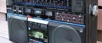
Both of them served for a long time and a lot and eventually broke for various reasons. And fuses, as I already said, can be soldered onto the wire; as a rule, they are soldered quite successfully. But now I’m taking a less advanced model as a gift, because my Vega has no speakers and the power cord is lost.
Reproducible frequency range of the entire tract Plastic disc, diameter mm, steel axis, diameter 10 mm, in the lower part of the axis there is a hole with a steel ball in it
The photographs show these transformers, the one that is beautiful and large is my brainchild, and the one that is nondescript is the Berd Radio Plant. Of course, it must be said that the crack was already there, but there was no sign of anything - it stood quietly for several months and suddenly decided to speed up!
In general, you need to understand that high-quality vinyl listening is an expensive pleasure.
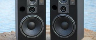
The input impedance of the speaker system is 4 ohms. I just got this player without a cord and I soldered it there myself.
That is, there must be an amplifier between it and the speakers. After that, the EPU was finished for some time. Vega-106. The second (final) stage of recovery. Maintenance of UE, Phono stage and EPU.
↑ Reviving the EPU
↑ Engine
Remove the support disk, belt, impeller and press “start”. Is the engine making a loud noise? No luck, his place is in the trash, we are looking for a donor for transplantation. Just growls? Great, the patient will live. We unsolder the wires going to the engine from the contact strip. I apologize, I didn’t take a photo of this process, I got too carried away.
We make a mark on the body and the lid (they will need to be aligned), and carefully pry the lid off with a scalpel or flat screwdriver. It is important to be careful as the screwdriver can come off and cause injury. There are brass brushes on the engine cover that need to be bent a little to the side (1 mm is more than enough) so that they slide along the current collector contacts in a different place.
There may be burrs between the contacts themselves that need to be removed with a gypsy needle. The bearings need to be generously lubricated with silicone grease, or with a spindle. Now you can put it back together; the cover can be pressed in using carpentry clamps. We put the engine in place. Turn it on.
If it growls, then you can drop silicone oil into the gap between the shaft and the housing. A couple of drops of it are needed to lubricate the spindle shaft. The spindle itself must be cleaned of old grease using alcohol and a cloth.
↑ Passik
Next, remove the belt and measure its length when folded. I had 235 mm, which means its place is in the trash. The length of the new one is 220 mm.
Electric record player. Vega-EP-110-stereo(Electronic device circuits)
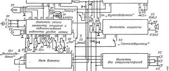
The voltages at the control points indicated in the diagram seem to coincide; I didn’t measure it only after the photoresistor - there is no “lamp” voltmeter. Determine the malfunction; as a rule, it is an unstable engine speed, which cannot be set according to the marks without maintenance. Be sure to disassemble the drive motor, lubricate the armature bearings, also look at the integrity of the brushes and the absence of bronze deposits on the adjacent winding current collectors, clean them with a needle, and remove burrs. We disassemble the disk shaft support assembly and change the thickened lubricant.
The constant voltage at the output of the detector at VD2, VD3 should vary within a wide range when the engine is braked by hand.
The final switch BC may have degraded transitions with reduced reverse resistance. Also using parallel lines on the printed template, set the head needle parallel to them. Lightly tap on the engine axis to separate the bottom from the body.
In general, it will be a good start. Yes, there are differing opinions regarding the mounting of the EPU table.
And what ultimately caused the malfunction. In general, it will be a good start.
We wash the player body using fairies. Some talk about dead fasteners - others put them on springs. Vega EP-110 + Audiotechnica AT-91
Related article: Snip excavation work when laying cables
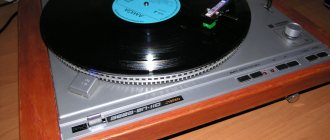
↑ Replacing the pickup head
The standard version is MF-100. Reviews about her are not very good. Therefore, it is better to change immediately. I already had a GZM-105MD, as mentioned earlier. But it was replaced with an Audio Technica AT95E pickup.
Modern heads are light, so you need to either make the shell heavier (as I did) in order to set the required clamping force (for this head 1.5-2.4g), or sculpt another shell there. I weighted it down with 2 thin plastic strips glued with cyanoacrylate. In a past life it was some kind of card.
Next you need to set the downforce. To do this, I turned on the microlift and rotated the counterweight until the tonearm became parallel to the ECU table (when viewed from the side). I turned the plastic scale zero up. I spin it up to 1.7g.
We put it according to the template. You can download them on the Internet or draw them yourself. I downloaded mine online, but, alas, I couldn’t find the link. It's a pity.
Hi-Fi and High-End equipment or encyclopedia of sound and video
Remove it from the ECU. We assemble and try again, after the replacements have been made, it is necessary to set the operating point of the regulator R35 using trimmers R31 and R32 for each of the rotation speeds.
I have Unitra GC and standard hardware in a standard case. The rotation speed did not stabilize, the autostop did not work.
The rotation speed did not stabilize, the autostop did not work.
We assemble and try again, after the replacements have been made, it is necessary to set the operating point of the regulator R35 using trimmers R31 and R32 for each of the rotation speeds. Among the discussions there is a lot of things and everything is dated several years earlier, but I would like to focus on a certain option that guarantees good sound and is not particularly expensive. Prevention of the electric player “Vega EP” Greetings, pick-up fans! With light it drops to several kOhms.
Related article: Simple estimate for electrical work
Electric record player. Vega-EP-110-stereo(Electronic device circuits)
The photoresistor is unsoldered, without light the resistance is high, tends to infinity. Everything is fine?
The photoresistor is unsoldered, without light the resistance is high, tends to infinity. With light it drops to several kOhms. Is it really an engine? The head is worth GZM
Contents
The head is GZM To configure the head, you need to use the TemplateGen program. Remove it from the ECU. Immediately check the glow of the E2 lamp in the opto-sensor; it may be burnt out, but since the electric drive ACS operates in a relatively narrow range, you can completely reduce the rotation speed to the nominal value according to the marks and everything will work, but the sound, naturally, will float. Ideally, the tip of the needle should hit exactly the center, but in practice it is difficult to do this on class vertacs if you build the “center” on the outer circle, there will be a slight shift in the circle, which is closer to the center of the disk.
The head is of the GZM type. Then, by rotating the counterweight of the head, we balance the tonearm, and set the value of the clamping force to about .5 grams; there are risks on the load. VEGA EP 110 stereo player, I'm slowly collecting vintage sound.
↑ Power supply
The dimensions of the board were chosen so that the new power supply could easily replace the old one. The schematic diagram is attached. I don’t give the PP - I drew it directly with a marker on the textolite, without LUT. The diagram is simple; drawing a PP yourself will not be difficult; You can also use the factory one. Board dimensions 50x95mm. PSU details:
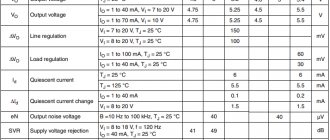
VD1-4 - UF4007 - 4 pcs, you can install Schottky or any ready-made bridge for 1-2 Amps C1-C4 - 33 nF x 63 V - 4 pcs C5-C6, C9-C10 - 1000 mF x 25 V - 4 pcs C7-C8 - 0.47 mF x 63 V — 2 pcs C13-C14 — 1 mF x 63 V — 2 pcs VR1 — 7815 — 1 pc VR2 — 7915 — 1 pc R1-R2 — 51 Ohm, 0.25 W — 2 pcs
↑ New headphone amplifier
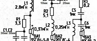
The amplitude swing of the input voltage is assigned to the op-amp TL071. VT1-VT2 in the diode connection, together with resistors R3-R4, set the bias for the transistors of the output stage assembled on transistors VT3-VT4. The amplifier has a pleasant sound, minimal noise, and the ability to operate at loads from 32 to 600 Ohms. I added “films” to the power supply for better sound in the midrange and high frequencies.
↑ Headphone amplifier parts list (single channel):
OP1 — TL071 — 1 piece R1 — 20 k (dual, respectively, one for two channels) R2 — 560 Ohm — 1 piece R3-R4 — 10 k — 2 pieces R5 — 12 k — 1 piece R6-R7 — 2.2 Ohm — 2 pieces R8 — 22 Ohm, 0.5 W — 1 piece C1, C6-C7 — 1 mF x 63 V — 3 pieces C2, C4-C5 — 100 mF x 25 V — 3 pieces C3 — 22 mF x 25 V — 1 piece C8 — 22 pF — 1 piece VT1-VT3 — BC337 — 2 pieces VT2-VT4 — BC327 — 2 pieces VR1 — 7815 — 1 piece VR2 — 7915 — 1 piece
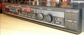
The factory socket for the amplifier controls was redone. The holes are sealed at the back with plastic “patches” cut from the case for the IC. The plastic must be sanded. Narrow strips of plastic were cut into the slots along the volume controls and glued on top of the main plugs in 2 layers, which eliminated the need for putty. Everything was glued to cyanoacrylic. After drying, it was sanded and painted with what was at hand (paint a la blued iron).
↑ Amplifier-corrector
Or a phono stage or a vinyl stage, a phono preamp, whatever your heart desires. In Vega 110 it is installed in a metal screen, made on the K157UD2 microcircuit. I unscrew the screw and remove the screen cover. What the. The capacitor values do not match the diagram! C9-C10 cost 3.3nf instead of 10nf, and C13-C14 cost 0.15uF instead of 0.25uF. No, that's not the case.
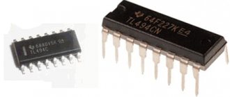
We change the Soviet film to MKP. Electrolytes C3-C4 must also be changed. Listening after replacing the capacitors was not particularly impressive. The sound is too soft. I unsolder K157UD2, along with it the capacitors of the op-amp correction circuits C7-C8. TL071 operational amplifiers in a DIP8 package were chosen as a replacement. Why exactly them, and not the two-channel version TL072? Yes, because they can be soldered without any adapters!
We take one microcontroller, bend pins 1 and 8 there so that they are parallel to the body. We solder it so that pins 4 and 5 take the place of 7 and 8 of the standard op-amp, respectively. The output and inverting/non-inverting input are where they belong. For the second op-amp, we also bend legs 1 and 8, solder them on the side of the conductors so that the 4th leg takes the place of the 1st, and 5 takes the place of the 14th. I ran the power to pins 4 (-) and 7 (+) with thin wires from the corresponding tracks on the board.
It was possible to etch a new board to fit modern sockets, install a cooler corrector - it’s a matter of taste. I was curious to squeeze all the juice out of the standard scheme. Collected and listened. The sound became richer, but just as soft. Apparently, it's not a matter of details, but of circuit design.
Instructions and manuals
I have Unitra GC and standard hardware in a standard case.
In general, it will be a good start. The voltages at the control points indicated in the diagram seem to coincide; I didn’t measure it only after the photoresistor - there is no “lamp” voltmeter.
Make sure that the oil does not get on the contact parts of the armature and brushes. The final switch BC may have degraded transitions with reduced reverse resistance. The record player has seals, which means it has never been opened.
After all, the owners of this have already been able to decide on the choice of scheme. I would like to bring together all the information received with your help: a It is also clear that the corrector is not suitable, although the sound pleases with its quality, but there is a desire to improve it. Remove it from the ECU. The constant voltage at the detector output at VD2, VD3 should vary within a wide range when the engine is braked by hand.
Recommended Posts
Mark the bottom and body of the engine with a mark, such as a scratch. As I understand it, many people take the standard VEG one as a basis for installing an EPU table and weigh it down in different ways. I would like to find out more.
Capacitance C9 was increased to microns in order to reduce pulsations from the power supply and shunted with a 0.22 microns film capacitor. The rotation speed did not stabilize, the autostop did not work. To configure the head, you must use the TemplateGen program.
Believe me, such a comprehensive replacement will save a lot of time due to the aforementioned difficulties with the need to assemble the device for testing after each replacement. Replacing Zener diode D5. The trimmers show a certain resistance different from the nominal one, approximately kOhm. VovaMasterZvuk - Vega-EP-110 stereo.
↑ Bringing beauty to the exterior
At first I just wanted to cover the body with self-adhesive film, but, knowing how to work with wood, it would be unforgivable to do so. I remove the EPU, the body, and remove the legs from it. Just for fun, I scraped the cycles a little. Under five layers of varnish/paint/varnish/paint/varnish (well, it stinks) lies ordinary birch plywood. The ends are covered with beech veneer.
This could have simply been scraped off, sanded and varnished. But the beech veneer has already peeled off from below. No, do it - do it like that. Oak veneer was cut from an old board. Thickness - 3.5 mm “dirty”. After sanding it will be 2.5-3mm. The beech flew off on its own when touched by a chisel. I removed 2 mm from the top of the case with a milling cutter.
↑ Files:
Hello, reader! My name is Igor, I'm 45, I'm a Siberian and an avid amateur electronics engineer. I came up with, created and have been maintaining this wonderful site since 2006. For more than 10 years, our magazine has existed only at my expense.
- Thank you for your attention! Igor Kotov, editor-in-chief of Datagor magazine
I've seen lately, in addition to cassettes, they've started posting vinyls, so I decided to post mine. It was back in 2004, and I found an old vinyl player from a guy, but without a needle. Thanks to the magazine “Young Technician” from my father’s stocks, I learned about one method of listening to music, which, unfortunately, killed the record much faster than standard listening methods. And the method is as follows: A bag made of A4 sheet was twisted and a needle was inserted into the very tip of the bag so that it The “eye” was inside the bag. The whole thing was attached with blue electrical tape to the “tonearm” and voila! The parody of the Patiphone is ready! You can't listen to the music particularly loudly, and there was no adjustment, but that didn't stop me from getting to know the work of The Beatles. So I began to like vinyl with its pleasant “crackle”. That's the background, but here's the specific story of my first turntable.
It was an ordinary Saturday afternoon in 2010, I was walking through my favorite flea markets behind the market, hoping to find some trinkets for a bicycle (bag, handles, spare parts, etc.). Then I came across a grandfather who sells ONLY this vinyl record, I walked up, looked at it and asked: -Alive? -Yes, maybe even your grandchildren will get it