Problems solved by anode-heat transformer
An electronic transformer for powering a tube amplifier is responsible for heating the tubes. If there are some design flaws - for example, a drop in output power and the need to warm up the tubes - the presence of the device in the tube amplifier circuit provides:
- Reducing the sensitivity of equipment to changes in supply voltage.
- Signal distortion, the sources of which are the stages of the tube amplifier, is reduced.
- The anode voltage component (300 V), which is dangerous for humans and the elements of the amplifier circuit, is eliminated.
- There is no bias in the circuit.
- Sound quality improves.
These positive features are realized against the background of the power of a tube amplifier, which reaches 4...6 W (and more if the speaker system used has good sensitivity). The gain varies due to the use of lamps with different characteristics. An anode-filament transformer does not require shielding, but it increases the requirements for the quality of insulation of the windings of the primary and secondary windings: there is life-threatening voltage there.
To realize the benefits, it will be necessary to connect the amplifiers in a symmetrical bridge circuit, which simplifies the requirements for the transformer: in particular, there is no need to filter the anode voltage, and the requirements for lamp synchronization are reduced. The transformation ratio of the device is assumed to be no more than 1:2. Then power transformers for tube amplifiers will provide not only phase inversion, but will also play the role of matching ones, guaranteeing that very galvanic isolation, the absence of which often causes unpleasant interference and background.
Important! To warm up the circuit elements, it is better to start listening to music and sound fragments after 60 minutes.
↑ Out of 36 “changes” - 136 are “constant”, this is real!
The reader will exclaim: “I just criticized multipliers, talked about Ohm’s Law, and on you!”
But first things first. Sometimes you can take advantage of shortcomings, everyone knows this from life experience. Based on this postulate, I began to design my own power supply. My presentation would not be complete without describing the portrait of my main character, or rather anti-hero, a modern small-sized transformer. A little trip into the past. Of course, the best available were transformers of the TAN series, military grade. There were also transformers with a power of about 15 watts from the indicator circuits of machine tools with winding voltages of 6.3 and 120V. They powered incandescent and neon bulbs. The quality was also quite good, reliable screed, impregnated with bakelite varnish. Or maybe they were made specifically for preamps? Joke. Unfortunately, they went down in history along with the Soviet past. This is where I finish with the lyrics and proceed to physics.
It all started with the appearance in the distant twentieth century of “T” series transformers with built-in voltage “sags”. Back then they were affectionately called “transformers with reduced copper and steel consumption.” Do you feel where the wind is blowing? Nowadays it has become politically incorrect to write about reduced copper consumption, so it seems that the voltage drop under load is a matter of course, like the rising of the Sun. We know where the Sun rises; this is where transformers are supposedly made that overheat at the stated rated load. To protect against a very likely fire, all the “dregs” with built-in fuses were invented. The presence of this “protection” is positioned as an advantage when they “focus” on you about transformers with “unique” characteristics. But if we consider the transformer from the standpoint of the quality and reliability of the power supply, then the voltage drop in its windings should be minimal, and the idle speed should approach zero. Everything else is deceit. Naturally, if these requirements are met, the transformer cannot get very hot, and it needs a thermal fuse, just like in a ski bath.
You may ask why I have been “poisonous” about transformers for so long? Here's why. The transformer is the basis of the power supply. The quality and safety of the device as a whole depends on it. Therefore, it is necessary to approach the assessment of the parameters of a transformer quite consciously; this saves nerves, money and protects health.
I carried out financially and mentally expensive laboratory work on the topic “electricity”. I won’t bore the reader with all the details, I’ll just say that several “patients” finally became indecently heated while idling. When connecting the rated load, the voltage “happily sagged” to the declared level. However, due to the appearance of an ominous stench, at the urgent request of the wife, the tests were curtailed and one transformer “received a residence permit” in the trash can.
Features of design and calculation of anode-heat transformer
How to make an electronic transformer for a tube amplifier? For a successful solution, it is worth remembering some of the operating features of tube amplifiers. These amplifiers are considered lower level devices than single-ended amplifiers, but still provide the necessary output power.
The problem with a two-stage amplifier is the non-ideal attenuation of emerging distortions with suppression of even harmonics. But, if it is possible to keep the level of distortion at a low level, then this circumstance will not further affect the operation of the circuit.
Another characteristic of two-stage tube amplifiers is high overall feedback, which is used to obtain the required damping factor values. This is important because anode transformers are often used to increase output power for low-ratio tube amplifiers. They also strive by any means to reduce the number of intermediate components that ensure the passage of the signal, for example, to use only one interstage capacitor, and not to use electrolytic capacitors at all.
The winding data of the power transformer for a tube amplifier is determined from the considerations that lamp filaments often operate at high DC voltage and require windings with high voltage insulation.
It is usually not possible to combine high voltage windings with low voltage windings when the high voltage exceeds 3000 volts DC due to the danger of insulation breakdown. Therefore, large rectifier filaments must be heated by separate transformers. The exception is multiphase rectifiers, where the tube filaments are at high voltage and some of the secondary windings may be combined.
↑ Details
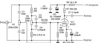
For assembly you will need a pair of radio tubes. You can use lamps of the 6N1P, 6N2P, 6N23P
.
Very good results are obtained with a 6N3P
, but it has a different pinout, and if you want to build an amplifier on it, pay attention to the location of the pins.
You can use a more powerful 6N6P lamp. When using it, you need to pay attention to the power of the filament transformer. It must provide a voltage of 6V at a current of at least 2A or 12V at a current of 1A. All of these lamps, with the exception of 6N6P
, are always available on any old tube TV, so there will be no problems with the acquisition.
Features of the location of incandescent windings
Low capacitance filament windings are sometimes required for high frequency circuits. at small rated voltages, for example, for low power amplifiers. Here, air occupies most of the space between the windings. At larger ratings the problem becomes more complex because the capacitance increases directly as the average coil turn length for a given winding spacing increases.
As the voltage increases, there comes a point after which leakage effects will require an oil-insulated winding, after which the capacitance increases. There is a capacitance limit below which the anode-heat transformer cannot be used.
Apart from the differences just mentioned, the winding design of power transformers for tube amplifiers is not much different from the design of small conventional AC frequency power transformers. The load is constant and has a unity power factor. Leakage reactance does not play a role due to its quadrature relationship to the load. However, the input voltage must be precisely sized to ensure proper filament life on the amplifier tubes.
In high-power tube amplifiers it is often necessary to protect the filaments from the high initial current they draw at rated filament voltage. This is achieved by automatically reducing the starting voltage through the use of a current limiting transformer, which has a magnetic shunt between the primary and secondary windings.
Important! When choosing a lamp design, you must remember: when the tubular filament is cold, the resistance of the filament is a small fraction of its operational value.
↑ SRPP Scheme
It is based on the so-called SRPP
cascade (Shunt Regulated Push Pull, in Russian the name sounds like this - cascade with dynamic load). So we have already begun to cast magic spells! A double triode lamp is used as an amplification lamp (two radio tubes independent of each other are placed in one glass container).
The lower half of the circuit is responsible for amplifying the signal, and the upper half plays the role of a dynamic load. The positive features of this connection are the high gain and low output impedance of the cascade. The amplifier copes with both low-impedance headphones with a resistance of 32 ohms and studio monitors with a direct current resistance of 250 ohms or more.
Setting up the circuit is no problem. After turning on and warming up the lamps (about 5 minutes), you need to check the voltage at the anode of the lower lamp or the cathode of the upper one. It should be equal to half the supply voltage (anode of the upper lamp). If this voltage differs from the norm by more than 5-10%, we adjust it by selecting the resistor Rk in the cathode of the lower lamp. It is recommended, during the setup period, to put there a chain of a 100 Ohm permanent resistor and a 330-470 Ohm resistor connected in series. After setting up the amplifier, we measure the resulting resistance with a tester and install a constant resistor of the closest possible value.
Reducing electromagnetic interference from other windings
Often, instead of using multiple anode power transformers, a single similar device is used that contains several independent windings for the various components of the tube amplifier.
The main one is the winding of the power supply in the lamp filament circuit. In these cases, interference occurs between individual parts of the circuit. For example, when using switching power supplies, the presence of short but intense current pulses complicates the operating conditions of the primary and secondary windings.
Such pulses have a frequency of 50 Hz or 100 Hz, depending on the type of rectifier used. They are very short and intense, and also contain a fair amount of high-frequency components that create electromagnetic interference. This interference further propagates through the main sections of the transformer. When noise reaches the filament winding, it simultaneously creates noise in the cathode circuit. Outwardly, they are perceived as low-frequency noise, which was already mentioned at the beginning of the article.
Interference can be reduced by shorting it to ground using low capacitance capacitors connected at both ends of the device. The winding data of the power transformer for the tube amplifier does not change.
Interestingly, any type of transformer built into a tube amplifier circuit is capable of setting a different sound frequency by simply adjusting the ohmic resistance values of the speakers.
↑ Element base
Mounting is mounted, capacitors are mounted in clamps.
All details are the most common. Transformers TP-132-3 and TP-132-14 were used; I do not indicate the manufacturer, because I can’t be completely sure of their origin, the appearance is visible in the photo.
The transformer supplying the filament heats up noticeably at less than half the load, the anode supply transformer is slightly warm, although it was purchased in 2006. Of course, you can use toroidal or sealed transformers. In any case, a fuse is required, which is dictated by compliance with fire safety measures. Just don’t be alarmed, this requirement simply must be met by default; when using the specified transformers, the margin is more than 50%. The “D3SB60” diode bridge was selected according to the mounting method and housing type.
Stabilizer “7806” for 6 Volts. It makes no sense to add extra parts to get 6.3 Volts; the optimal filament voltage is exactly 6 Volts. It is no longer possible to make it even lower, the lamp gain drops, and all other parameters will “float”. If the filament voltage is 12 Volts, then a “7812” stabilizer is used, the datasheet is similar to “7806”. Don't forget to increase the operating voltage of C4 and C5!
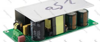
The transformer can be taken TP-112-12. The 1N4007 diodes far exceed the reliability requirements; they were just at hand. Modern technologies make it possible to make good diodes, the voltage drop across them is minimal, and there is no heating at all. C1 and C2 are taken with a significant margin because The load characteristics of the doubler depend on them. C3 also has the highest possible capacity (I have C3 220 uF, resistor R1, 10 kOhm). If you are limited by the size of the power module, then you can recalculate the capacities based on your needs. It is better to take a domestic MLT of 1 Watt for resistance R1; if the resistor is from an unknown manufacturer, use 2 Watt. Now a few words about editing. The installation is quite compact, but the temperature conditions allow it.
The bridge and stabilizer are installed on
KPT-8
(I prefer domestic paste and consider it generally the best). The stabilizer chip is isolated from the chassis, this makes subsequent ground wiring easier. If you are firmly convinced that there will be no interference, you don’t have to isolate it. I always insulate if the radiator is electrically connected to the housing. Thus, the negative low and high voltage buses in the power supply are separated.
Capacitors C4 and C5 must be connected in close proximity to the terminals of the stabilizer, otherwise it may work unstable or not start at all.
Diode D3 (in the stabilizer circuit) performs a protective function and if an abnormal load disconnection is excluded, it can not be installed.
I do not recommend powering the indicator LED with a stabilized voltage; it is better to make a separate output, as indicated in the diagram. Take an economical LED, this is especially important if the op-amp is also powered from the low-voltage channel. Current limiting resistor R2 of the LED, calculate after measuring the voltage with the main load connected. As a bauble, I have a Standby switch, you can eliminate it, although to preserve the “health” of the lamp I would leave it.
PS About the clamps for fastening capacitors, you can read in my message: “Dedicated to fans of wall-mounted mounting of lamp ultrasonic units.”
Good luck to everyone, Mikhail.
↑ Assembly
Next, using a specific example, I will describe my version of the implementation of the circuit of this amplifier. Once upon a time, I saw a photo of a PC case modding project created by an Arsgera modder called “Poet”. In this computer case, made in the form of a wooden box with the profile of A. S. Pushkin on the top cover, an antique silver candlestick was used as a decorative element. I liked the idea then, but I would like to use the candlestick not just as a decorative element. This idea came to mind when I was thinking about how to externally design the future amplifier.
I took a trip to souvenir and antique shops and ended up purchasing a pair of (albeit not antique, but beautiful) candlesticks and a small wooden box from a wine set. This is how it supposedly should have turned out.
I measured the internal dimensions of the box and used them to make a metal chassis on which I placed transformers and electrolytic capacitors. There is also a block with terminals on which all other parts will be soldered. The base was a steel plate cut from a waste side of a computer case.
It was necessary to make a hole in the back wall of the box to install a power connector, a power switch, and jacks for headphones and a signal cable. Big trouble awaited me here. When I was drilling the box, the drill accidentally became skewed and the box cracked. The beautiful red piano varnish that covered the box fell off in several places and the appearance was ruined, as I thought, completely.