The Hitachi company released a new modification of the interconnect cable SAX-102 in 1984. In its production, Oxygen Free Copper (OFC) technology was used, using oxygen-free copper. After this, many companies began to develop this technology, trying to obtain the purest possible material that can be used in various production processes. Why is this material interesting?
Historical background, characteristics of copper
Copper belongs to the group of basic chemical elements. In its natural (pure) form, it is a metal with a red-orange tint. It is used for the manufacture of a very large number of products, which include electrical wires, dishes, pipes, car radiators, etc.
Archaeological information suggests that copper began to be used more than ten thousand years ago. Thus, a copper pendant discovered in the northern regions of modern Iraq was made around 8700 BC.
Copper has high thermal and electrical conductivity and is easily processed both hot and cold. It has very high corrosion resistance. This is due to the fact that copper creates a very thin protective oxide layer on its surface as a result of its reaction with oxygen.
Copper has found wide application in the production of acoustic, electrical and other wires, present there as a high-purity metal or with small additions of silver, arsenic, phosphorus, tellurium, and sulfur.
Receiving process
Highly purified oxygen-free copper is obtained through a process called electrical refining. It deposits on the cathodes of electrical cells, as a result of which it has another name - cathode copper. Purity reaches about 99.99%. This metal is also called oxygen-free copper, which has a high degree of purification (OFC - Oxygen-Free Copper).
Molten pure copper is subsequently poured into special molds that have square or rectangular cross-sections. This process occurs in a vacuum, in the absence of oxygen, which prevents it from penetrating the molten metal. The absence of oxygen impurities in such copper significantly increases its electrical conductivity and strength.
Development of oxygen-free copper production technology
The metal that conducts electric current consists of granules that have a crystalline structure. In places of transitions, structural disturbances occur. This occurs due to the presence of impurities in the metal. Oxides are most often an “obstacle” to the passage of electric current. Therefore, the less oxygen, the less oxides. Standard copper has 5000 oxide granules per 1 meter of cable.
The development of oxygen-free copper technology can be divided into three stages
- OFC technology and its varieties
- OSS - Professor Ono's method
- Production of conductors based on composite materials
Purity
Oxygen-free copper OFC has different degrees of purity. The purity of the metal is indicated as follows: “*N”. In place of the asterisk (*), insert a number that reveals information about the number of nines after the decimal point. Thus, the OFC 6N grade of oxygen-free copper reports that it contains 99.999999% pure metal. The amount of foreign impurities is 0.000001%.
The first production of 6N grade copper was carried out in 1985 in Japan by Nippon Mining Co. Highly purified oxygen-free copper went into mass production in 1987. The main areas of application then became acoustic wires and interconnect network cables.
Currently, such pure copper is produced by quite a lot of manufacturers in the world, including in the Russian Federation.
Some companies claim that they have achieved a degree of purification higher than 6 -7N, 8N, etc. But it should be taken into account that at present there is no unity in determining standards for the purity of oxygen-free copper and its quality. In some cases, the presence of any impurities is simply not taken into account. Typically, such foreign inclusions include silver.
Recommendations for the selection and use of speaker and audio cables.
March 30, 2009, 09:50
Recommendations for the selection and use of speaker and audio cables.
“Considerable interest in recent years has focused primarily on the very complex and complex task of producing high-quality cables and accessories, which was previously not deservedly forgotten. Unfortunately, contradictory statements from a huge number of manufacturers have led to serious contradictions. As a result, there are exceptional difficulties in separating the real facts from the fiction, which really frustrate the potential buyer, especially when it is obvious that significant material costs in order to improve the sound quality arise even when choosing a suitable interconnect or speaker cables.”
For the precise interaction of Hi-Fi components, in accordance with the characteristics of their use, the requirements for interconnect cables increase, taking into account the need to unconditionally take into account the subjective assessment through listening, which is ultimately the decisive factor in the final selection of a suitable cable, regardless of sometimes to the highest characteristics of one or the other.
We are absolutely confident that our recommendations will help the reader to obtain basic information about the relationship between construction, cable design and sound quality, thereby helping in the selection of suitable speaker and interconnect cables according to their intended purpose.
There's more to the sound quality than just the characteristics of the wires themselves.
The following three types of wires are commonly used in Hi Fi systems:
- Network cables
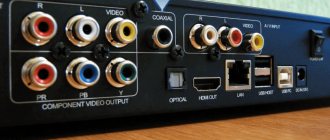
- Interconnect cables for precise audio signal transmission.
- Speaker cables for transmitting signals from amplifiers to speaker systems.
While network cables affect quality, the two most important for great sound are the latter two, interconnects and speaker cables. In cable design, there are three fundamental factors that determine sound quality:
- Characteristics of the material from which the conductor is made.
- Characteristics of the insulator material.
- Cable design characteristics.
Appropriate selection of quality conductor materials contributes to improved resolution, bass clarity, sound imaging, depth and height, while selection of insulating materials, together with cable design, is responsible for tonal fidelity and fidelity.
Type of conductors
TPC (Coarse Copper) TPC is a common copper conductor widely used as electrical wires such as network and low-cost audio wires. Electrolytic copper is brought to the melting point, and then cooled, turning it into an electrical cable by drawing, by repeated rolling, to the required dimensions. Coarse copper, which undergoes this heat treatment (melting and cooling) in air, contains about 300~500 oxygen impurities per mole.
OFC (oxygen-free copper) OFC is obtained by processing in an inert gas, this process in the absence of oxygen, produces a very low content of oxygen impurities, about 10 particles per mole (10ppm). The conductivity of OFC is 0.5% to 2% higher than that of TPC. OFC can also be annealed to produce a less grainy structure.
PCOCC (Pure Ono Continuous Casting Copper) PCOCC is a 'state of the art' process excellence in conductor technology. PCOCC is produced by an exclusive and patented continuous casting method developed by Professor Ohno of the Chiba Institute of Technology. The PCOCC process is a hot casting process that produces a homogeneous or single-crystalline conductor from ultrapure copper, with a low content of oxygen and hydrogen impurities. This material transformation has an additional significant advantage, it reduces the level of stress and strain in the copper, thus the PCOCC has greater flexibility, the PCOCC has a higher so-called gravity and a higher “Q”, hence the PCOCC has mechanical insulation or resistance to induced electromagnetic vibrations inside the conductors are excellent.
The PCOCC mono crystal copper conductor has no grain boundaries in the direction of signal travel, therefore PCOCC does not interfere with even the most delicate audio signal, and has the lowest distortion of any conductor material possible. Since its introduction in 1986, continuous research and development into the PCOCC method has resulted in ever greater purity of copper produced. PCOCC copper with a purity of 99.99999%, known as “7N” because of the seven nines, will in the future be a hallmark of the highest quality cables.
Chemical and physical properties of copper taking into account inclusion
| PCOCC | OFC | TPC | ||
| Purity | >99.997 | >99.99 | >99.9 | |
| Density | × | 8.938 | 8.926 | 8.75 |
| max | 8.940 | 8.932 | 8.88 | |
| Presence of gas | O2(ppm) | <5 | <10 | 200~500 |
| H2 (ppm) | <0.25 | <0.5 | >0.3 | |
| Hydrogen embrittlement | Complete absence | No | Yes | |
Properties of starting materials
| PCOCC | LC-OFC | TPC/OFC | ||
| Conductor diameter | 5mmψ | 15mmψ | 1.6mmψ | 0.9mmψ |
| Grain length | >500mm | >50mm | <0.5mm | <0.05mm |
| Grain length after rolling to 0.1mm¢ | >1,125.00m | <13cm | <4mm | |
| Number of grains in a 2m length cable | 1 | >15 | >400 | |
Differences in Cable Design The cable used in the design has either a solid or multi-core conductor configuration, in accordance with the purpose for which it was designed. A stranded structure usually has three configurations, each of which has its own characteristics and, accordingly, advantages.
- Bundle-shaped structure of the conductor
The bundle-shaped structure is a production method in which the cores that make up the conductor itself lie as if in a bundle in one direction. Typically, this bundled design is used in network cables and, occasionally, in some Hi-Fi and audio systems. The cross-section of such a stranded conductor is not perfectly round, therefore, the cable used to transmit the signal of this design is subject to the influence of the reflected signal due to fluctuations in the resistance characteristics in the longitudinal direction of the cable, ultimately affecting the sound quality.
- Concentric arrangement of conductors
Concentrically located conductors usually consist of a large number of concentrically twisted strands that form the conductors themselves. The center located in the middle of the conductor lies on the same straight line with the center of the diameter of all other conductors. Adjacent strands within a conductor are usually twisted in opposite directions. The identical arrangement of conductors in the longitudinal direction gives an ideal circle in cross-section along the entire length, which ensures good signal transmission characteristics and stable resistance characteristics of the entire conductor.
- Rope arrangement of conductors
Rope arrangement is one of the varieties of concentrically twisted conductors that have the same number of internal conductors, which, in turn, consist of bundle-shaped or concentrically twisted strands. The rope arrangement is a very good design for use in good quality speaker cables that require a large cross-section while maintaining their flexibility.
- Monolithic conductor
Unprecedented quality when using PCOCC conductor. It should be noted that all compromises in the designs of the three production methods mentioned above are completely removed in the case of a perfectly round conductor having a monolithic structure, which can have a wide variety of sizes, in accordance with your needs. Such materials are Super PCOCC, the so-called original “AS CAST” and are not processed or stretched repeatedly to obtain the desired dimensions. FS-2T15S speaker cable and FA-11S interconnect cable, an example of the so-called “AS CAST” conductors, are the most advanced conductors that Furutech makes, and they are used in the best cables.
Various conductor characteristics
Conductor resistance The drop in signal level is directly dependent on the conductor resistance. This drop characterizes the amount of energy consumed when the signal passes along the cable, and the smaller the drop in level, and, therefore, the lower the resistance of the conductor, the better.
Another important detail is in the case of speaker cables, when high conductor resistance causes a decrease in the damping factor. The speaker coil generates its own electromagnetic force, which in turn causes back movement in the speaker cable and, in extreme cases, can damage the power amplifier.
Direct current resistance is directly related to the cross-section of the conductor and depends on the material from which it is made; the larger the diameter and purer the material, the lower the direct current resistance.
When transmitting high frequencies with alternating current, many extraneous factors play a role, and the resistance of the conductor increases due to the skin effect, the attraction effect and the actual loss of current. The figure shows the frequency response of three Furutech speaker cables. FS-2T20P, FS-2T35P and FS-2T15S, the first two, multi-core design, 2 square meters in diameter. mm and 3.5 sq. mm, respectively, and the third, a conductor made of monocore with a diameter of 1.5 mm. It should be noted that we are considering the audio frequency spectrum from 20 Hz to 20 kHz, where the frequency characteristics of all three cables remain practically unchanged, however, as frequencies increase from direct to alternating current, the conductor resistance increases accordingly. It could be argued that these frequencies are outside the audio audible spectrum, but this is not the case, these high frequencies affect timbre, sound presentation and contribute to the clarity and uncoloration of high frequency audio reproduction, thus being constructed from the highest quality material, with incorporating the most advanced technology, along with efficient processing, is the key to hi-fi excellence.
Skin effect Current flow tends to concentrate on the surface of a conductor as frequency increases. The situation requires study, due to losses in the metal of the conductor, high-frequency electromagnetic waves or the reaction inside the conductor when current passes.
In practice, when high frequencies are transmitted to the peripheral surface, they do not pass through the central part of the conductor, and the reduction in effective cross-sectional area leads to an increase in the resistance of the conductor, which leads to a drop in signal level, and, as a result, deterioration in sound quality.
Attraction effect When conductors are close to each other and a high frequency current flows in each conductor, the currents will flow as long as the distance between the conductors remains constant if the directions of movement of the currents are the same. On the other hand, currents flow while attraction is maintained if the directions of their movement are opposite. In this case, the resistance of the conductor increases if the current flow is not uniform.
Types of Absorbers
Materials The materials most commonly used for electronic cables are PVC (Polyvinyl chloride) and LDPE (Low Density Polyethylene). In commercial applications, PVC is commonly used in cables for low voltages, typically less than 600 Volts. LDPE, with its good dielectric properties, is commonly used as the insulation material in communication cables for telephones and the like. for high voltage network cables and for video and digital interconnect cables.
The best materials are FEP (Teflon) and PP (Polypropylene). Teflon has excellent dielectric properties. Teflon is heat-resistant, and is known to be used as a surface for frying pans and irons, which means that the temperature to insulate the conductor material must be of a higher order, usually from 400 to 500 degrees Celsius, and at this temperature, the surface of the conductor can oxidize.
Polypropylene is a clean, stable material with excellent insulating properties, including dielectric constant. PP also exhibits better mechanical properties such as vibration resistance and is the material of choice for Furutech's speaker and analog interconnect cables.
Currently, rubber is used as insulation, a rarely used material in electronics, because... PVC (polyvinyl chloride) is more flexible and exhibits better qualities in terms of wear resistance and resistance to various reagents, etc. in particular, when used as the outer sheath of wires.
Basic insulating materials and their electrical characteristics
| Material Properties | Low Density Polyethylene (LDPE) | PVC | Polypropylene | Teflon FEP |
| Volume resistance (Ohm*sq.cm) | >1017 | 1012 ~1015 | 6.5 X 10¹⁴ | >1018 |
| Dielectric constant (50~106 Hz) | 2.3 | 4~8 | 2.25 | 2.1 |
| Tangential dielectric loss (50~106Hz%) | 0.02~0.05 | 8~15 | 0.02~0.06 | 0.02~0.07 |
* Teflon is a trademark of Du Pont.
Electrical characteristics of insulating materials Insulating materials have four electrical characteristics that are very critical to the design of cables.
Volume resistance is the resistance per unit area, for direct current, and is an index of insulation quality.
Dielectric force is the voltage at which dielectric failure occurs when applied to a material with a diameter of 1 mm.
Dielectric constant (described below) and dielectric derating are fundamental characteristics in cable design.
Tangential dielectric loss is the main characteristic of the loss of dielectric quality when alternating current passes through a conductor coated with insulating material.
Relative dielectric constant
The relative dielectric constant is the most important parameter in cable design. The relative dielectric constant (Es) is defined as the ratio of the electrostatic capacitance for capacitors with parallel plates in a vacuum (Co) and the electrostatic capacitance in the presence of insulating material (C) and is defined as: Es=(C/Co). Thus, it can be interpreted as the degree of vacuum polarization (Es=1). An insulating material containing a large number of ions, for example PVC, polarizes when exposed to electrical voltage.
The changing structure of such an insulator around a current-carrying conductor causes a loss of dielectric properties, leading to loss of signal and a decrease in transmission speed, changing the relative dielectric constant of the insulator.
Figure 9 shows the frequency response of the relative dielectric constant (Es), between two types of cables, Furutech VVF, a network cable with PVC insulator and Furutech FS-2T20P speaker cable with PP insulation and PVC outer shield
Capacitance The electrostatic capacitance of a cable is determined by the location of the two conductors and the dielectric constant of the insulator. Impregnated polyethylene and propylene are used in low-capacity cables such as Furutech FD-11, FV-11 and FA-21 because... impregnation reduces the dielectric constant and, therefore, stabilizes the frequency characteristics.
In the audio range, the amount of capacitance, together with the resistance of the conductor, controls the level of signal attenuation, and the lower the level of attenuation, the better the cable.
Resistance characteristics
There is a fundamental pattern that for the transmission of high frequency signals, such as from video, digital sources, the transmitted signal corresponds to the resistance of the cable. The correct type of cable is a 75 ohm coaxial design and if a different conductor is used the signal will be partially reflected at the connection such as RCA connectors and cannot be transmitted pure due to the fact that either the rising or falling the square wave is deformed or the waveform is distorted, causing errors which in turn degrade the sound quality.
Shell
Cables for interconnection are placed in a sheath to protect the signal from external noise. There are two types of protection, one includes protection against electrostatic noise, the other against magnetic noise. To prevent electrostatic interference, a highly conductive metal such as copper wire or aluminum foil is usually used. Since the protective effect is in inverse proportion to the resistance of the shell from which this protection is made, it is necessary to reduce the resistance of this protective material in order to increase the current flowing through the protective shell, which creates a protective barrier against external noise.
Ferrites (iron, etc.) must be used in cables to combat magnetic fields. But, this type of protection is not used in audio cables due to the fact that the cable becomes thick and hard. In layman's terms, twisting insulating conductors can have the effect of suppressing magnetic fields.
However, cable designers do not call this magnetic shielding. The concept of magnetic protection applies exclusively to the use of ferritic materials.
Recommended use of interconnect cables
Balanced and Unbalanced Interconnect Cables Interconnect cables can be classified into two categories according to their type of construction and connection, they are balanced and unbalanced. Balanced type has an equivalent conductor with the same capacitance, resistance, and endurance characteristics, such as the Furutech FA-11S and FA-21, which have a pass-through and return path for the signal. Electrically, these conductors are at the same potential as ground. These cables, in addition to the conductors, contain a separate protective sheath, which can be considered as a necessary barrier to external noise by connecting the sheath to the housing. The free solder (end) should be connected to ground or the ground connector at the end of the wire that connects it to the signal source. This connection configuration in the interconnect cable is called balanced.
A non-balanced design has a forward and return line that are not equivalent in terms of design features or electrical parameters, such as the Furutech FV-11 and FD-11s cables.
These are cables that have a coaxial design, and the protective shield, or sheath, is used as the return line. In general, the resistance of the protective shield is lower than that of the conductor itself.
Balanced and Unbalanced Signals Signals used in audio technology can be classified into two types, balanced and unbalanced. The voltage generated in the coil or piezoelectric element of a cartridge or microphone is essentially a balanced signal, described as a modulated alternating current electromagnetic wave.
The signal used in CD players is an unbalanced high-frequency signal that is transmitted with a reference ground potential (0 volt).
Suitable interface between source signal and interconnect cables For optimal signal flow, it is necessary that the interconnect cables meet the requirements of the source audio signal, i.e. balanced interconnect cable for analog and unbalanced for digital signals.
Unfortunately, in practice these prerequisites are usually completely ignored, as stated above in the chapter on impedance characteristics, the interconnect cable for transmitting video or digital signals is required to have a resistance of 75 ohms.
In order to get rid of external noise and EMI (electromagnetic interference) in particularly significant analog signals, it is necessary to use balanced cables between the amplifier and preamp, deck and preamp, turntable and preamp, etc.
Selecting Cables Make sure the cables you use meet the following requirements:
- Conductor material.
The materials from which the conductor is made are usually the major contributors to improved audio resolution, hence, check the purity of the material, grain sizes, crystal length, mono or polycrystalline structure, PCOCC, LC-OFC or OFC, these are the factors that determine the degree of purity, and hence the sound resolution.
2. Conductor design. When stranded conductor construction is used, especially in speaker cables, check the cross-section to see if it is a perfect circle in diameter. When the cores lie in clusters in the longitudinal direction, they do not have a perfect circle shape, therefore, the resistance characteristics of the cable cannot be guaranteed unchanged, as a result of the reflection of the signal as it passes, causing deterioration in sound quality.
3. Insulating material Frequency fluctuations, in accordance with the parameters of the dielectric constant of the insulating material, is the characteristic that determines the speed of signal transmission. All Furutech cables have low dielectric loss and stable frequency response across the entire audio spectrum.
4. Protective shell The outer shell is necessary to absorb mechanical and electromechanical vibrations, at the same time being sufficiently flexible, i.e. soft and pleasant to the touch for ease of use.
Guide to using cables An audio cable, consisting of a conductor, insulation... is a very delicate design, a science-intensive product, and, therefore, certain requirements must be observed to maintain it in proper condition.
- Do not twist, bend or break the cable
- Don't squeeze
- Don't bend too much
- Do not place the audio cable parallel to the network
- Do not run the audio cable parallel to ferritic structures.
- Do not leave either end of the cables exposed. Never connect the positive and negative conductors to avoid a short circuit.
- Disconnect cables that are not in use
- Do not try to connect the cables to each other
- Clean contacts periodically to protect against oxidation
- Do not use unreasonably long cables
Enhancing your listening pleasure Appropriate cables, properly selected according to their purpose and the Hi-Fi system being used, will transmit without any distortion all the wonderful world contained in the original source, making a significant and usually effective contribution to the sound quality of the system, to your complete enjoyment. satisfaction. Before any upgrade to your Hi Fi system, simply test the possible improvement without changing the components of your system, by using the correct speaker and interconnect cables, taking into account all the recommendations outlined above. An authorized dealer will be happy to help you understand your system, giving you the opportunity to experience significant improvements in sound quality using our designs, free of charge.
Advantages of metal
The benefits of oxygen-free copper OFC include the following:
- in a vacuum, when heated, it does not break and does not become brittle;
- capable of easily changing shape during cold deformation (when exposed to pressure at room or close to room temperatures);
- does not change color when exposed to different conditions;
- the average electrical resistance of such a metal is constant;
- electrical conductivity is always high;
- this metal is homogeneous in its structure;
- Can be easily processed by high-temperature soldering and welding.
Use in home audio
The high-quality speaker wire industry markets oxygen-free copper as having increased conductivity or other electrical properties that are supposedly favorable to transmission horns. In fact, the conductivity characteristics for the conventional C11000 oxygen-free (OF) boiler (ETP) and the more expensive C10200 are identical;[12] and even the more expensive C10100 has only one percent higher conductivity, which is not significant for audio applications.[12]
OFC is, however, sold for both audio and video signals in audio and home theater systems.[12]
Areas of use
Due to its qualities and properties, oxygen-free copper has found application in a variety of products, namely:
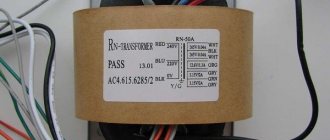
- transformer windings are made from it;
- used in the production of coaxial cables;
- used in electronic systems and devices;
- an essential metal in superconductors and linear accelerators;
- it is an important structural element of telecommunications wires and cables intended for use under water;
- is part of the current transformer wiring.
Oxygen-free copper is also used in vacuum technology. It is indispensable in the design of vacuum distribution systems and semiconductors.
It is widely used in the manufacture of products for the space industry.
Other areas where oxygen-free copper is used include: radio electronics, microelectronics, radio and instrument making, nuclear energy, jewelry and construction industries.
Wires and pipes designed to operate in strong electromagnetic fields are made from it. Oxygen-free copper is the basis for the manufacture of electrochemical anodes.
Copper cathode cables: application
Modern cable products made using oxygen-free copper are characterized by increased conductivity. This makes it possible to carry out high throughput electrical signals with smaller wire cross-sections.
However, it is worth noting that oxygen-free copper cables have not found widespread use. And all because wires made of this metal are highly expensive. To achieve the required parameters, they use simple copper ones with a large diameter, preferring not to spend money on expensive products made of oxygen-free copper.
But there are also areas in which high conductivity in combination with a small wire diameter is preferred. This is necessary to ensure, among other things, an aesthetic appearance. These areas include the production of musical equipment, high-quality headphones, as well as those where it is necessary to obtain devices that reproduce high-quality professional-level sounds.
When using such copper, its advantages in resisting internal corrosion are noted. Thanks to this property, oxygen-free copper wires do not lose their characteristics over time. For this reason, cables filled with this metal are used in conditions where there is high humidity.
Standards
Electrical conductivity is usually stated relative to the 1913 International Standard for Annealed Copper of 5.8×10⁷/. Advances in the refining process now produce OF and ETP copper that can meet or exceed 101% of this standard. (Ultra-pure copper has a conductivity of 5.865×10⁷ S/m, 102.75% IACS.) Please note that OF and ETP boilers have the same conductivity requirements.[5]
Oxygen plays a beneficial role in improving the conductivity of copper. During copper smelting, oxygen is deliberately introduced into the melt during the process to remove impurities that would otherwise impair conductivity.[6]
There are advanced purification processes such as the Czochralski Process than can be used to reduce impurity levels below the C10100 specification by reducing the copper grain density.[7][8][9][10] There are currently no UNS/ASTM classifications for these specialty boilers, and IACS conductivity data for these boilers is not available.
