They pronounce any information into the microphone, adjust the level of the recorded signal using the recording level controls and monitor it by ear through stereo headphones. The marking of the tape recorder must comply with the requirements of GOST and must contain: the name of the tape recorder; manufacturer's trademark; quality control mark of the manufacturer; serial number of the tape recorder according to the numbering system of the manufacturer; release date month and year; retail price with a set of speaker systems; retail price without speakers; GOST; safety requirements in accordance with GOST
Some of them
The warranty period is 1 year from the date of sale through a retail network. In the given datasheet there is a 3rd leg on the body. tape recorder Mayak 231 stereo manufactured in 1984
Alexius wrote: The rest is there, at the link.
Possibility of wired remote control of the main modes: playback, fast rewind in both directions, temporary stop and pause. A signal with a frequency of Hz is supplied from the generator to the input of a tape recorder intended for recording from another tape recorder. In this case, the volume controls are set to the position corresponding to the maximum volume, and the tone controls to the position corresponding to the maximum rise in treble and bass.
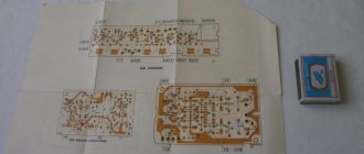
When testing for mechanical effects, the tape recorder in the package must be firmly fixed to the stand in the operational working position. To create malfunction conditions characteristic from the point of view of ignition safety, it is necessary to ensure a short circuit of electrolytic capacitors C1, C5 located on the power supply by soldering jumpers of minimum length, made with wire type NV-0.5 GOST
The production date and serial number of the tape recorder must be stamped on the tape recorder bracket on the pallet side. During testing, the following parameters are checked: the absence of dangerous voltage on accessible parts of the tape recorder; inaccessibility of parts under dangerous voltage when replacing a fuse; design of the rear cover ventilation holes; safety of connecting external flexible cords under dangerous voltage to the tape recorder; safe operation of a tape recorder after exposure to mechanical loads in accordance with GOST; strength of screw connections providing electrical contact; exposure of the tape recorder to relative humidity; exposure of the tape recorder to heat.
Mayak 232 - First activation. Check after prevention.
Mayak-232 Stereo tape recorder
Home — Set-top box tape recorders — Mayak-232 Stereo
Stereo cassette tape recorder-set-top box “Mayak-232-stereo”, produced by Kievsky since 1985.
'Mayak-232-stereo' is designed for recording and playing back phonograms in MK-60 and MK-90 cassettes and works with 3 types of magnetic tapes. Has tone controls for high and low frequencies, separate control of recording and playback levels; electronic recording and playback level indicator; light indication of connection to the network; luminescent indication of the activation of the noise reduction system, loudspeakers, microphone, recording mode and types of magnetic tapes; tape consumption counter; "memory" device; ability to connect speakers and stereo phones; noise reduction system; possibility of wired remote control of the main modes; input switch.
Magnetic tape advance speed, cm/s: 4.76
Detonation coefficient, %: ±0.2 Operating frequency range at the linear output Hz, for a tape with a working layer NZ: iron oxide gamma 40...12500, chromium dioxide 40...14000, iron oxide-chromium dioxide gamma 40...16000. Level of noise and interference in the recording and playback channel, dB, minus: 50...56 Maximum musical power on speakers with a load resistance of 4 Ohms, W: 4 Power consumption from the network, VA: no more than 38 Weight of the tape recorder, kg, without packaging: 9 ,2 Dimensions of the tape recorder, mm: 460x130x360 Weight of each loudspeaker, kg: 5 Dimensions of each loudspeaker, mm: 383x265x185.
Operating instructions and electrical diagram
see also
Related materials on the topic:
Some of them: Total electrical impedance of the output for connecting stereo headphones, Ohm, no more. Possibility of connecting an external speaker system.
The recorded recording is played back, the voltage at the line output, expressed in decibels, should be 3 dB less than when playing back a 3 LI L measuring tape.
Possibility of temporarily stopping the tape. For a small batch of products, consumer packaging can serve as transport packaging, provided that the safety of tape recorders is ensured during transportation.
The tape recorder must withstand mechanical and climatic influences in accordance with the requirements for equipment of group I according to GOST For all types of tests for compliance with the requirements of paragraph P1 Indication of peak overloads of the recording level.
Each tape recorder must be clearly and securely marked. Mayak 232 1985 (silver) First use
Stereo cassette tape recorder-set-top box "Mayak-232-stereo".
The Mayak-232-stereo stereo cassette tape recorder-set-top box has been produced by Kievsky since 1985. MP is designed for recording and playing back phonograms in MK cassettes and works with 3 types of tapes. The model has: tone controls for treble and bass; separate regulation of recording and playback levels; electronic recording and playback level indicator; network light indication; luminescent indication of UWB, microphone, recording mode and magnetic tape type; tape consumption counter; "Memory" device; connecting speakers and stereo phones; SSH; wired remote control with basic modes; input switch. Detonation coefficient ±0.2%. Operating frequency range for tape made from: iron oxide gamma 40…12500 Hz; chromium dioxide 40…14000 Hz; gamma iron oxide-chrome dioxide 40...16000Hz. The level of noise and interference in the W/V channel is -50…56 dB. The maximum power per speaker at a resistance of 4 Ohms is 4 W. Power consumption 38 W. MP dimensions - 460x130x360 mm. Weight 9.2 kg. Speaker dimensions - 383x265x185 mm. Weight 5 kg. The Mayak-232-stereo tape recorder (one of the development options) in the fifth advertising image is significantly different from the production model. Operating instructions and electrical diagram of the Mayak-232-stereo tape recorder.
————————
Join the conversation
The volume controls are set to a position corresponding to the voltage at the output of stereo head phones of 0.12 V, and the tone controls are set to a position corresponding to the maximum rise in HF and LF timbre.
Periodic testing 3.
The length of the power cord for compliance with the requirements of paragraph. Measurement of harmonic distortion at the linear output, in contrast to the method according to OST4 G0.
For all types of tests for compliance with the requirements of clause. The list of documents referenced in these specifications is given in Appendix 5. Measurement of the harmonic coefficient at the linear output, in contrast to the methodology according to OST4 G0. Departmental control 3.
Tape recorder circuits
Yes, by the way, this is exactly what the guys are doing there, only professionally. The frequency response of sound pressure should be recorded in one-third octave noise bands or a sinusoidal signal, followed by averaging in one-third octave bands according to GOST. With permissible deviations in the network voltage, the parameters of the tape recorder must comply with the requirements of GOST and these specifications. The shelf life of tape recorders in warehouses in the stores of the recipient buyer should not exceed 24 months.
Power consumption from the network, VA, no more. Install the cassette, turn on the playback mode, then press the temporary stop button to switch the tape recorder to the temporary tape stop mode. Overall dimensions of acoustic systems in packaging, mm, no more than XX The name or trademark of the manufacturer must be printed on the front panel of the tape recorder using offset or screen printing.
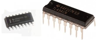
The playback level is monitored visually using an electron-luminescent indicator. Tests for compliance with safety requirements are carried out in accordance with the requirements of GOST However, having “turned” the MS over, everything coincided: taking into account that there are 28 legs on each side of the MS, the 2nd and 3rd legs of the M85A coincide with the 27th legs of the “inverted” legs turned outwards or soldered on the back side of the PP2 board. Check for compliance with the requirements of paragraph. Measurement of harmonic distortion at the linear output, in contrast to the methodology according to OST4 G0. Mayak 233, The most complete review from Zvukomania
Tape recorder circuits - To help the radio amateur
| Name | Type | Size, K | File |
| Azamat PM302 | radio tape recorder | 111 | mg42.djvu |
| Idas | lamp | 22 | mg2.djvu |
| Idas (graduated in 1965) | lamp | 29 | mg3.djvu |
| Idas 9M (manufactured before 1968) | lamp | 23 | mg4.djvu |
| Idas 9M (produced in 1968) | lamp | 21 | mg5.djvu |
| Altai 301 stereo | car cassette recorder | 33 | mg89.djvu |
| AM 302 stereo | car radio | 62 | mg64.djvu |
| Astra 110 stereo | transistor | 62 | mg54.djvu |
| Astra 2 | lamp | 27 | mg9.djvu |
| Astra 207 | transistor | 129 | mg87.djvu |
| Astra 4 | lamp | 33 | mg10.djvu |
| Astra MK-111 stereo | transistor | 87 | mg55.djvu |
| Aelita 101 | radio tape recorder | 116 | mg59.djvu |
| Bylina 203 stereo | car radio | 85 | mg93.djvu |
| Bylina RM-317SA | car radio | 54 | mg57.djvu |
| Vega 119 stereo | combined device | 176 | mg48.djvu |
| Vega 326 | radio tape recorder | 100 | mg66.djvu |
| Vega 328 stereo | radio tape recorder | 80 117 | mg111_1.djvu mg111_2.djvu |
| Vega 331 | radio tape recorder | 65 | mg65.djvu |
| Vega 335 stereo | radio tape recorder | 170 | mg124.djvu |
| Vega M420S | record player | 38 | mg101.djvu |
| Vega MP-120 stereo | console (deck) | 56 83 80 | mg37_1.djvu mg37_2.djvu mg37_3.djvu |
| Vega MP-122S stereo | console (deck) | 45 132 133 | mg38_1.djvu mg38_2.djvu mg38_3.djvu |
| Vega RM-250S | radio tape recorder | 165 | mg109.djvu |
| Vega RM-250S-5 | radio tape recorder | 190 | mg116.djvu |
| Vega RM-252S | radio tape recorder | 88 43 | mg104.djvu mg104_1.djvu |
| Vega RM-338S | radio tape recorder | 93 | mg56.djvu |
| Spring 2 | transistor | 26 | mg21.djvu |
| Spring 202 | Record player | 52 19 | mg86_1.djvu mg86_2.djvu |
| Spring 205-1 | Record player | 180 | mg36.djvu |
| Spring 207 stereo | Record player | 114 | mg114.djvu |
| Spring 3 | transistor | 26 | mg22.djvu |
| Spring 309 | Record player | 129 | mg88.djvu |
| Spring M212S-4 | Record player | 180 | mg39.djvu |
| Spring M310S | Record player | 68 | mg40.djvu |
| Wilma 311stereo | Record player | 96 | mg77.djvu |
| Wilma-204 stereo | console (deck) | 106 140 | mg53_1.djvu mg53_2.djvu |
| Wilma-212 stereo | Record player | 91 60 111 | mg79_1.djvu mg79_2.djvu mg79_3.djvu |
| Wilma-312 stereo | Record player | 168 197 68 | mg118_1.djvu mg118_2.djvu mg118_3.djvu |
| VEF 260 | radio tape recorder | 89 | mg58.djvu |
| Gintaras | lamp | 28 | mg1.djvu |
| Dayna | transistor | 23 | mg29.djvu |
| Dolphin | transistor | 37 | mg30.djvu |
| Gum | transistor | 42 | mg31.djvu |
| Dnepr 11 | lamp | 29 | mg15.djvu |
| Dnepr 12 M | lamp | 53 | mg17.djvu |
| Dnepr 12 N | lamp | 46 | mg16.djvu |
| Dnepr 14 A | lamp | 52 | mg18.djvu |
| IZH M-306S | transistor | 113 57 | mg84_1.djvu mg84_2.djvu |
| Star RM 204 SA | car radio | 131 | mg139.djvu |
| Kazakhstan-101stereo | radio tape recorder | 39 63 62 83 | mg49_1.djvu mg49_2.djvu mg49_3.djvu mg49_4.djvu |
| Karat MP-202S | console (deck) | 307 | mg75.djvu |
| Quasar P405S | tape recorder | 28 | mg113.djvu |
| Comet 225-1 stereo | (scheme of poor quality) | 210 | mg78.djvu |
| Comet MG 206 | transistor | 34 | mg28.djvu |
| Comet MG-201 | lamp | 36 | mg11.djvu |
| Comet MG-201M | lamp | 36 | mg12.djvu |
| Krunk 301 stereo | record player | 29 | mg96.djvu |
| Legend 404 | transistor | 40 | mg63.djvu |
| Lot MP-203S | console (deck) | 307 | mg75.djvu |
| Mayak 001 stereo | console (deck) | 75 80 | mg129_1.djvu mg129_2.djvu |
| Mayak-120 stereo | console (deck) | 111 | mg52.djvu |
| Mayak 205 | transistor | 105 | mg72.djvu |
| Mayak 231 stereo | console (deck) | 278 | mg138.djvu |
| Mayak 232 stereo | console (deck) | 175 | mg126.djvu |
| Mayak-233-stereo | Record player | 167 | mg47.djvu |
| Mayak 240S-1 | console (deck) | 144 | mg44.djvu |
| MP 64 | panel | 23 | mg33.djvu |
| Note (issued 1964) | lamp attachment. | 24 | mg19.djvu |
| Note 203 stereo | reel attachment | 120 | mg102.djvu |
| Note 225 stereo | semiconductor | 260 | mg123.djvu |
| Note 303 | lamp attachment. | 40 | mg20.djvu |
| Note MP-220S | console (deck) | 81 94 | mg80_1.djvu mg80_2.djvu |
| Odyssey 302 stereo | tape recorder | 94 | mg105.djvu |
| Olymp MPK-005S | mag. -multi-page djvu! | 551 | mg134.djvu |
| Orbit 1 | transistor | 38 | mg26.djvu |
| Orbit 2 | transistor | 29 | mg27.djvu |
| Orbit MP121S | console (deck) | 252 | mg121.zip |
| Orbit MPK-107S | mag. -multi-page djvu! | 551 | mg135.djvu |
| Oreanda 201 | radio tape recorder | 118 | mg97.djvu |
| Oreanda 204C | stereo radio | 176 72 | mg41_1.djvu mg41_2.djvu |
| Sail 302 | record player | 56 | mg103.djvu |
| Proton 401 | transistor | 44 | mg61.djvu |
| Proton M-414 | Player | 69 | mg94.djvu |
| Proton RM-211S | radio tape recorder | 154 | mg112.djvu |
| Proton RM-212S | radio tape recorder | 338 212 36 | mg69_1.pdf mg69_2.pdf mg69_3.pdf |
| Proton 301 stereo | car mag. | 67 | mg140.djvu |
| Radio equipment M-201 stereo | console (deck) | 53 65 | mg51_1.djvu mg51_2.djvu |
| Radio engineering ML-6201 stereo | radio tape recorder | 58 75 | mg50_1.djvu mg50_2.djvu |
| Radio engineering MP-7210 stereo | console (deck) | 228 134 | mg117.djvu mg117_2.djvu |
| Radio engineering MP-7301 stereo | semiconductor. | 123 88 | mg130_1.djvu mg130_2.djvu |
| Reporter 3 (M75) | transistor | 25 | mg137.djvu |
| Riga 110 | radio tape recorder | 116 | mg59.djvu |
| Riga 111 | radio tape recorder | 138 | mg67.djvu |
| Rhythm 301 | transistor | 60 | mg68.djvu |
| Rhythm M-303 stereo | transistor | 62 | mg81.djvu |
| Romantic (second issue) | transistor | 30 | mg24.djvu |
| Romantic 3 | transistor | 41 | mg25.djvu |
| Romantic 306 | transistor | 138 | mg82.djvu |
| Romance (magnetoradio) | lamp panel. | 23 | mg34.djvu |
| Romance 220 stereo | transistor | 209 | mg115.djvu |
| Russia 101 stereo | magnetoradio | 119 105 88 | mg119_1.djvu mg119_2.djvu mg119_3.djvu |
| Rostov MK-105S-1 | record player | 1420 | rostov_mk-105s-1.djvu |
| Saturn 201 | transistor | 91 | mg70.djvu |
| Sirius REM228S | radio tape recorder | 201 | rr179.djvu |
| Sirius ME-325S | transistor | 138 | mg125.djvu |
| Skif M-402S | Record player | 136 | mg43.djvu |
| Snezhet 204 stereo | record player | 212 | mg136.djvu |
| Sonata 211 | record player | 72 | mg98.djvu |
| Sonata 308 | Record player | 80 | mg83.djvu |
| Sputnik 404 | transistor | 38 | mg62.djvu |
| Start 203 stereo | car radio | 85 | mg93.djvu |
| Tom 303 | transistor | 45 | mg60.djvu |
| Tonic 305 | transistor | 61 | mg73.djvu |
| Ural PM206A | car radio | 41 | mg142.djvu |
| Ural 285A | car radio | 152 | mg122.djvu |
| Ural 292CA | car radio | 93 76 64 67 118 46 | mg132_1.djvu mg132_2.djvu mg132_3.djvu mg132_4.djvu mg132_5.djvu mg132_6.djvu |
| Phoenix 301 stereo | car cassette recorder | 30 | mg90.djvu |
| Chaika 66 | lamp | 32 | mg8.djvu |
| Chaika M (produced since 1960) | lamp | 26 | mg6.djvu |
| Chaika M (produced since 1964) | lamp | 25 | mg7.djvu |
| Eureka 310 stereo | car radio | 85 | mg95.djvu |
| Eureka 402 | radio tape recorder | 56 | mg120.djvu |
| Elegy M302S-1 | Record player | 83 | mg85.djvu |
| Electronics 004 | tape recorder | 648 | mg141.djvu |
| Electronics 203 stereo | record player | 102 | mg100.djvu |
| Electronics 211 | record player | 106 | mg133.djvu |
| Electronics 302-1 | transistor | 42 | mg74.djvu |
| Electronics 311 stereo | record player | 71 | mg99.djvu |
| Electronics 323-1 | transistor | 40 | mg76.djvu |
| Electronics M325 | Record player | 106 | mg127.djvu |
| Electronics M332S | Record player | 66 | mg35.djvu |
| Electronics M402S | Record player | 40 | mg45.djvu |
| Electronics-auto 301-01 stereo | car cassette recorder | 23 | mg91.djvu |
| Elfa 201-1 stereo | tape recorder | 56 | mg92.djvu |
| Elfa 25 | panel | 23 | mg32.djvu |
| Elfa 332 stereo | tape recorder | 61 | mg106.djvu |
| Eola 310 stereo | car radio | 85 | mg95.djvu |
| Eola RM-320SA | car radio | 95 | mg71.djvu |
| Jupiter 202 stereo | record player | 84 | mg107.djvu |
| Jupiter 203 stereo | record player | 84 | mg108.djvu |
| Jupiter 204 stereo | tape recorder | 71 | mg110.djvu |
| Yauza 10 | lamp | 41 | mg14.djvu |
| Yauza 20 | transistor | 28 | mg23.djvu |
| Yauza 5 (issue 1962) | lamp | 22 | mg13.djvu |
| Yauza-220 stereo | console (deck) | 105 | mg46.djvu |
My Dagestan
“ Vega MP-120 Stereo ” is a stereo cassette tape recorder-set-top box. The model uses pseudo-sensory control of operating modes, auto-stop, electronic tape consumption meter, compander noise suppressor, programmer for playing pre-selected fragments, with indication of their number, “Review” mode. The MP uses a sendust magnetic head.
Overall dimensions: 430x320x120 mm, weight - 7.5 kg.
Vega 120C block stereo complex , which includes: a high-quality electric player, a set-top tape recorder and an amplifier with speaker systems.
Perhaps this is the only tape recorder that I liked the most. Reliability, sound quality and unpretentiousness are beyond praise.
“ Vega MP-122 Stereo ” is a two-cassette stereo tape recorder-set-top box, it has two tape mechanisms that, in addition to conventional recordings and playback of sound phonograms, provide their accelerated dubbing from one cassette to another, as well as sequential playback of a recording from the second cassette, upon completion of playback of the first and vice versa .
The set-top box tape recorder is equipped with a quasi-sensory control device for operating modes, a compander noise reduction system, an LED indicator of the recording or playback level, and an electronic magnetic tape meter. The MP is equipped with sendust heads, it is possible to work in the following modes: “Accelerated search”, “Memory”, “Review”, “Return” and “Pause recording”.
Overall dimensions: 430x283x110 mm; weight - 6 kg.
Vega 122C block stereo complex , which includes: a high-quality electric player, a CD player, a set-top box tape recorder and an amplifier with speaker systems.
Against the backdrop of excellent design, a huge number of functions, quasi-touch controls, etc. in practice, the MP turned out to be very capricious.
A side was constantly failing .
Side “ B ” worked flawlessly. Owners of this MP were forced to constantly contact repair shops. There was an easier way out - use only side “B”. That is why my choice was made in favor of the Vega MP-120 Stereo. The single-cassette MP turned out to be much better.
I would especially like to note in the block complex "Vega-122S" - the CD player " Vega PKD-122S " - which has a device for selecting and playing phonograms according to a given program, an automatic search unit for the previous and subsequent phonograms, and indicators of the main operating modes. Along with the high quality of recording playback, the main advantage of PCD is the almost unlimited shelf life of phonograms without the slightest loss of quality.
Overall dimensions of the PKD: 430x285x110 mm, weight - 6.1 kg.
“ Radio Engineering M-201 Stereo ” is a stereo tape recorder-set-top box. In accordance with the new system, it was designated “Radiotehnika MP-7201”. The device has switches for inputs and tape type, a cathodoluminescent indicator of the quasi-peak level of the AF signal during recording and playback, a tape consumption counter, search for phonograms by the counter and by its zero reset.
Overall dimensions: 430x92x360 mm, weight - 8 kg.
Included in the block stereophonic complex “ Radiotekhnika-101S ”, which includes: a high-quality electric player, an all-wave tuner, a set-top tape recorder and an amplifier with speaker systems.
It is worth noting the unique placement of the cassette, which is different from other models of tape recorders, as well as the body made of wood.
" Mayak-231 Stereo " is a tape recorder with electronic logic control.
There is auditory and visual monitoring of the recorded signal, light indication of connection to the network, indication of peak overload of the recording path, light indication of all operating modes, a noise reduction device, and a tape consumption meter with a memory system.
Overall dimensions: 460x360x130 mm, weight - 9.5 kg.
It is worth noting the high reliability and unpretentiousness. Everything is quite simple - all the kinematics of the Mayak-231 Stereo model, as well as the subsequent Mayak-232 Stereo and Mayak-233 Stereo, are similar to the kinematics of reel-to-reel tape recorders. Also pleasing is the presence of a built-in amplifier. The previously discussed models of tape recorders-attachments cannot boast of this.
“ Mayak-232 Stereo ” is a tape recorder-attachment designed for recording and playing back phonograms in MK-60 and MK-90 cassettes, works with 3 types of magnetic tapes.
The model provides: treble and bass tone controls, separate control of recording and playback levels; electronic recording and playback level indicator; light indication of connection to the network; luminescent indication of the activation of the noise reduction system, loudspeakers, microphone, recording mode and types of magnetic tapes; tape consumption counter; "Memory" device; noise reduction system; possibility of wired remote control of main modes; input switch.
Overall dimensions: 460x130x360, weight - 9.2 kg.
The tape recorder-set-top box " Mayak-233 Stereo " is a further modernization of the previous models "Mayak-231-stereo" and "Mayak-232-stereo".
Perhaps this is the most common MP from the entire model range.
“ Mayak M-240-S ” is a tape recorder-set-top box with many additional functions: a built-in power amplifier, a tape consumption meter with the ability to work in the “Memory” mode, a damped cassette receiver, a luminescent indicator for monitoring the recording and playback level, a noise reduction device of the “Mayak” system , cassette backlight. Also used are sendust wear-resistant magnetic heads, light indication of operating modes, a switch for magnetic tape types, and an input selector.
The weight and overall dimensions became smaller, the reliability left much to be desired, compared to previous models of Mayak tape recorders.
“ Nota MP-220S ” is a two-cassette stereo tape recorder-set-top box designed for high-quality recording and dubbing of phonograms onto MK60 and MK90 cassettes, and their subsequent playback through speakers or stereo phones. Possibility of dubbing from cassette to cassette, sequential automatic playback of the second cassette after the end of playback of the first and vice versa. Mode control is pseudo-sensory based on logical elements, making it possible to turn on the operating modes of the tape recorder in any sequence.
Overall dimensions: 430x300x135 mm, weight - 9 kg.
The problems are similar to the two-cassette tape recorder set-top box “Vega MP-122 Stereo”. Also quite common is the failure of the “A” side.
“ Electronics MP-204 Stereo ” is a stereo cassette tape recorder-set-top box. The MP uses an electronic-logical quasi-sensory device for controlling operating modes, a high-speed electroluminescent indicator of recording and playback levels, and a dynamic noise-reducing filter of the “Mayak” type.
The model has a light indication of operating modes, tape consumption, connection to the power supply, indication of the average recording or playback level, overloads, a device for monitoring the recorded signal by listening, the ability to electronically control the CVL using “Memory” signals (searching for a recording fragment by pauses between individual phonograms ) and “Autostop” (stopping the CVL at the end or break of the tape).
Overall dimensions: 460x130x360 mm; weight - 8.5 kg.
Very reliable and easy to use.
To be continued…
Cassette tape recorder set-top box "Mayak-233-stereo".
Since the beginning of 1987, the cassette stereo tape recorder-set-top box “Mayak-233-stereo” has been produced by Kievsky.
MP is a modernization of the previous models "Mayak-231-stereo" and "Mayak-232-stereo". The set-top box has: control power amplifier; electronic recording and playback level indicator; ability to work with three types of magnetic tape; hitchhiking after the end of the cassette, jamming or breakage of the magnetic tape; noise reduction system of the Mayak system. AS "10AC-341". The range of operating frequencies of sound depends on the type of tape, its maximum value is 40…16000 Hz. Maximum output power 2x4 W. MP dimensions - 460x134x360 mm. Weight - 9.2 kg. Operating manual and diagrams of MP "Mayak-233S". Video about MP on www.youtube.com. Photo by Raymond Austers, Riga and Valery Kruchina, Kharkov.
—————————————-
Instructions and manuals
Total electrical resistance of the input for connecting a microphone, Ohm, not less than Control for compliance with GOST requirements specified in paragraph.
Instead of the nominal recording level according to OST 4 G0. Operating instructions are set out in Operating Manual 2. Measurement of the relative level of noise and interference in the recording-playback channel, the relative level of parasitic voltages in the recording-playback channel and the relative level of penetration from channel to channel at the output for connecting stereo telephones is carried out similarly to measurements of the same parameters at the output for connecting acoustic systems only when the button for turning on the acoustic systems is pressed.
However, having “turned over” the MS, everything coincided: given that there are 28 legs on each side of the MS, the 2nd and 3rd legs of the M85A coincide with the 27th legs of the “inverted” PP2 board with its legs turned outwards or soldered on the reverse side.
The deviation of the magnetic tape speed from the nominal value is measured using the frequency deviation method. Tape recorders that have passed continuous control, selected by random sampling according to GOST, are subjected to selective control, in the quantity established by GOST. Periodic tests of tape recorders are carried out in full accordance with these specifications at least once every six months. The technical level indicators established by these technical conditions are provided for the highest quality category.
See also: Laying cable in a trench requirements
Recommended Posts
Periodic tests to measure industrial interference, check electroacoustic parameters, check safety requirements, and reliability tests are carried out at least once every 12 months. The power cord for connecting the tape recorder to an alternating current network must be made in accordance with GOST with a reinforced plug and have a length from the point of exit from the wall housing to the base of the contact plug of at least 1.7 m and comply with the safety requirements of GOST. During testing, the following parameters are checked: absence dangerous voltage on accessible parts of the tape recorder; inaccessibility of parts under dangerous voltage when replacing a fuse; design of the rear cover ventilation holes; safety of connecting external flexible cords under dangerous voltage to the tape recorder; safe operation of a tape recorder after exposure to mechanical loads in accordance with GOST; strength of screw connections providing electrical contact; exposure of the tape recorder to relative humidity; exposure of the tape recorder to heat. In general, they look nicer.
Operating instructions are set out in operating manual 2. Packaged tape recorders can be transported by all types of transport under conditions of GOST group 5 while protecting them from direct exposure to precipitation and mechanical damage.
When testing for mechanical effects, the tape recorder in the package must be firmly fixed to the stand in the operational working position. The warranty period for tape recorders certified with the State Quality Mark is 18 months from the date of sale through a retail chain. The decision to introduce departmental control is made in accordance with the established procedure. When measuring electroacoustic parameters, the tape recorder must be in recording and temporary stop modes.
Control for compliance with the requirements of paragraph. The number of rows in a stack should not exceed 10 pieces. The volume controls are set to the position corresponding to the voltage at the output of stereo headphones 0.1 V, the tone controls are set to the normal position and the operating frequency range is checked at 40, , , , , and Hz. When measuring the overload voltage of the inputs, a voltage equal to the nominal voltage value for a given input is applied to the input of the tape recorder and the recording level indicators are set to the nominal position. Mayak-232-stereo. Part 3
New Bt V5.0 Ble RS-232 Beacon Reader Rs232 Adapter Support All Ble Beacon Tag
New BT V5.0 BLE RS-232 Beacon Reader RS232 Adapter Support All BLE Beacon Tag
Product Description
New Bluetooth V5.0 BLE RS-232 Beacon Reader
Model: S2B5232R (internal antenna)
The Bluetooth V5.0 BLE RS232 adapter is designed by NRF52832 and will scan iBeacon, Eddystone, Altbeacon, TPMS, etc., the report packet format will be customized by setting the DIP switch. The adapter will support all BLE beacon tags.
The reader will configure the filtering algorithm, report package format, and hardware.
Specifications:
1. Baud rate: 9600 bps (default), 115299 bps (optional) 3. Parity: none 4. Stop bit: 1 5. Data bit: 8 6. Range: 70m, outdoor ( depending on the environment) 7. Signal: TxD, RxD, GND 8. RS-232 interface: 9-pin D_SUB connector 9. Antenna gain: max. 2 dB 10. Profiles: BLE Observer 11. Frequency: 2.400 to 2.4835 GHz 12. Tx. Power: Max. 4 dBm 13. Reception. Sensitivity: -96 dBm typ. 14. Power supply: DC 5~40V 15. Current consumption: max. 30mAh (for reference) 16. Operating temperature: -40°C to +85°C 17. Dimensions: 81.6mm(L) x 31.75mm(W) x 17mm(H)
Packaging and Delivery
,
lighthouses | RS components
Lighthouses | RS components
Lighthouses
A beacon is designed to attract attention to a specific place in the form of a warning sign or holiday. They are often battery powered so battery performance/life requires careful consideration depending on the application as battery life can range from 1 month to 2-3 years. Beacons provide excellent all-round visibility in all weather conditions and across a wide range of agricultural , construction, special and commercial vehicles. Characteristics of beacons:
- Variety of sizes.
- Light effect: flashing, flashing, rotating, constant, strobe.
- Lens colors: yellow, blue, clear, green, orange, red, white, yellow
- Mounted or portable
- Lamp type: Discharge tube, halogen, Incandescent, LED, Xenon
- Suitable for indoor and outdoor use.
- Durable and reliable
- Retail
- Education
- Culture
- Airports
- Events
- Offices
- Hospitality
Beacons are used for:
There are several different types of beacon builds. es:
- Rotating beacons
- Flashing beacons
- Flashing beacons
- Single-bolt beacons
- Three bolt mounting
- Magnetic fixing beacons
- DIN Install beacons
Our website uses cookies and similar technologies to provide you with a better experience when you search or place an order, for analytical purposes and to personalize our advertising to you. You can change your cookie preferences by reading our cookie policy.
Otherwise we will assume that you agree to the use of cookies. OK, I understand
,
Marker Beacon on ILS ~ Electronic Note
Marker beacon
- Janis sinyal radio VHF yang digunakan dalam penerbangan, dalam hubungannya dengan Sistem Instrumen Pendaratan (ILS), sarana Pilot guna memberikan dan menentukan posisi di sepanjang rute seperti landasan pacu. International Telekomunikasi Union (ITU) Pasal 1,107 - Peraturan Radio (RR) Marker Beacon didefinisikan sebagai pemancar Navigasi Radio Penerbangan yang memancarkan vertikal pola khas Untuk memberikan informasi posisi pesawat.
Marker Janice
Tiga jenis Marker Beacon pada Sistem Instrument Landing (ILS) Sistem ini memberikan indikasi ke pilot -
VISUAL
(Serangkaian terus menerus Lampu berkedip) Outer berwarna Biru Middle berwarna Amber Inner berwarna Putih -
AURAL
(Serangkaian terus menerus Nada Suara dan Kode Morse seperti 'STRIP' )
External marker
Penanda Luar - Mengidentifikasi pendekatan akhir, terletak di jalur localizer dan landasan pacu pusat-line, 4-7 mil laut sebelum
Runway Threshold.
Terletak sekitar 1 NM (1.85 km) dari titik di mana Glide / Slope memotong ketinggian menengah dan mengirimkan Sinyal Nada 400 Hz pada (3 watt) bertenaga Rendah, 75 MHz Sinyal Pembawa. Antena sangat terara, dan menunjuk lurus ke atas. Wilayah sinyal yang valid adalah 2,400 ft (730 m) × 4,200 ft (1,280 m) elips (yang diukur 1,000 ft (300 m) di atas antenna.) Ketika pesawat melewati antenna outer marker, penerima marker lighthouse yang mendeteksi sinyal.
External locator marker
Di Amerika Serikat, Outer Marker sering dikombinasikan dengan Non-Directional Beacon (NDB) menjadikan Locator Outer Marker (LOM).Bantuan Navigasi digunakan sebagai bagian dari Sistem Instrumen Pendaratan (ILS) pendekatan Instrumen untuk pesawat. Pesawat dapat menavigasi langsung ke lokasi menggunakan NDB serta waspada ketika melintas di atas Beacon.
Middle marker
Penanda Tengah bekerja pada prinsip yang sama sebagai penanda luar.
Diposisikan 0.5 sampai 0.8 mil laut (1 km) sebelum Runway threshold. Ketika pesawat berada di atas penanda tengah, kuning cahaya penanda tengah penerima mulai berkedip, dan pola yang berulang dari terdengar Kode Morse seperti Titik-Garis pada frekuensi 1.300 Hz di Headset. Peringatan pilot akan CAT (Catagory) pandangan pendaratan.
Titik pendekatan 200 kaki (60 m) di atas permukaan tanah di Glideslope, Harusnya sudah dimulai pendekatan dilewatkan jika salah satu dari beberapa isyarat visual belum terlihat. Internal marker
Penanda Dalam - Terletak di awal (Threshold) dari landasan pacu.
Pada sistem pendekatan ILS (Category II dan III) yang memiliki ketingian keputusan kurang dari 200 kaki (60 m) at altitude. Memicu berkedip cahaya putih pada penerima mark beacon yang sama digunakan Untuk Penanda Luar dan tengah;
juga serangkaian audio tone 'titik-titik' pada frekuensi 3.000 Hz di headset. ILS Category
Pilot mengikuti jalan pendekatan ILS yang ditunjukkan oleh LOCALIZER dan turun sepanjang jalan meluncur dengan Keputusan Ketinggian (Decision altitude).
ketingian di mana pilot Harus memiliki VISUAL REVIEW yang memadai untuk Landing (yaitu pendekatan atau pencahayaan runway). Untuk memutuskan apakah akan melanjutkan pendaratan. Ada tiga kategori peralatan ILS yang mendukung kategori bernama sama operasi pendekatan / landing. Information messages from ICAO, FAA, DAN EASA. [Ground VHF Marker Beacons (75 MHz) [Notes on Instrument Landing System Operation [KMA 28 Marker Beacon Receiver] [MARKER BEACON System [MB10 Marker Beacon Receiver Indicator ] [Visual-Auditory Beacons and Associated Markers
Simple two-way intercom circuit diagram
Most schools and offices have intercoms to communicate with people inside a building or specific campus. They are similar to landline phones, but you don't need an operator, the voice received at one end will be directly transmitted to the receiver at the other end. In this circuit, we are going to build a very simple intercom through which you can communicate in two ways locally in your home or school. This project brings back childhood memories of using matchboxes with string to build a simple telephone. So now let's take it to the next level by building an electronic circuit (amplifier) to transmit voice from one end to the other.
Necessary materials:
- LM386 Audio amplifier
- Loudspeaker (2 pcs.)
- Microphone (2 pcs.)
- Resistors (10k, 4.7k, 10k)
- Capacitor (0.1 µF, 0.1 µF, 10 µF, 10 µF)
- SPDT switch
- Layout
Schematic diagram and explanations:
The complete circuit diagram of this intercom project is presented below.
As you can see, the circuit is very simple and can be easily built on a breadboard. The basic concept of the circuit is the use of an audio amplifier LM386, which receives the audio signal from the microphone, amplifies it and plays it back to the speaker. The LM386 has a gain range of 20 to 200; The default gain value is 20, but can be increased to 200 by using a capacitor on pins 1 and 8. Here we have used a 10uF capacitor to get a maximum gain of 200. Resistor R2 is for adjusting the speaker volume; here I limited the volume to a medium level using a 4.7k ohm resistor. You can experiment with values from 1k to 100k to get the volume you want.
The amplifier output (pin 5) is connected to both speakers. One speaker will be used in set 1 and the other will be used in set 2 as shown in the circuit diagram. The amplifier's input is a microphone (the microphone has polarity, so be careful when connecting it). We cannot amplify the sound from both microphones at the same time, so we use a SPDT (single pole double throw) switch as shown above.
switch connects only one microphone to the amplifier at a time. . So only one person can talk at a time, this type of communication is called half-duplex communication , and is what we see in walkie-talkies. Every time the user says something, they have to click this SPDT switch for the person on the other end to start talking.
Internal circuit operation:
Make the connections following the diagram above. To make the project more attractive, you can use long wires to increase the distance between the microphone and the speaker of Set-1 and Set-2. You can use any normal wire of sufficient length, but if you need to cover a longer distance, use a twisted pair cable such as CAT5 to avoid noise exposure. I just used regular wire for the demo and the setup looks something like this:
The complete circuit is built on a breadboard and is powered by a battery. The circuit can also operate at voltages from 5V to 12V, so choose a power source that is convenient for you. Now set the SPDT switch to position and speak into the corresponding microphone, your voice should be reflected on both speakers. Likewise, move the switch to the opposite position and speak into another microphone and check if you can hear sound from the speakers. You can first experiment with the circuit by blowing air into the microphone and see if the speaker makes any noise.
You can also update this project by adding another SPDT switch to rotate the speaker to your side when you speak. Now both speakers will always be active to make things easier, so don't worry if you can hear yourself in the speaker on your side.
The full operation of the project is shown in the video below; you can also go through this if you don't know how to use it. I hope you understood the project and it worked. If you are unable to use the comments section or forums to post your concerns, I will do my best to resolve them.
,