Modification of UMZCH Amfiton-U-101.
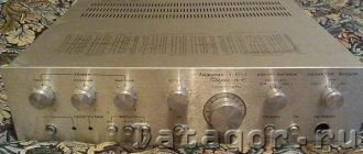
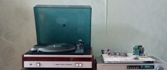
Easy adjustment of the output part of the Amfiton-U-101 amplifier. The description is intended for a trained reader. 1. Amfiton-U-101 As a donor for the body and radiators, a complete UMZCH Amfiton-U-101 was purchased and gutted
Photos were borrowed from the network, because... his mind was dismantled to the ground on the very first day. Naturally, there was no talk about restoration of the UMZCH (like “I replaced all the electrolytes with new ones”, etc.): only the final PA is needed. Initially, the plan was to leave the original power transformer, but something went wrong: upon arriving home, it turned out that the transformer was buzzing a lot. Therefore, the transformer had to be thrown out and replaced with a standard TPP-297.What goals were pursued: - throw out everything unnecessary from the UMZCH, leave only the output PA (i.e., turn a complete UMZCH into a terminal) - slightly modify the output stages (increase the rate of rise of the output voltage, Slew rate aka SR) - if possible, use existing radio components - replace the speaker protection circuit - spend some time on your hobby
2. Multisim 10 simulator program. Before taking up the soldering iron, the NI Multisim 10.0 simulator program (formerly Electronics Workbench) was called upon to help. This program has some features: - well calculates the frequency response and phase response of passive filters and cascades on transistors - well calculates the SR of cascades on transistors - when calculating the harmonic distortion coefficient Kg (THD) it is twofold: sometimes NI “guesses” everything perfectly, and sometimes it misses everything .
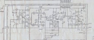
An example of a diagram when the calculated Kg (less than 0.01%) does not coincide at all with the actual measurements.
This pattern is NOT to be repeated!
Being collected live, an unsatisfactory Kg was obtained
It is this circuit that was assembled on the PP from the Amphiton-U-101 UM. But something went wrong, and this scheme had to be abandoned.
3.Offtopic. Another wish (also unrealized): I really wanted to assemble and listen to the Lanzar UM circuit, but this required manufacturing a PCB with dimensions similar to the native Amphiton-U-101 boards.
I had to “cut back on the sturgeon.” Not to mention that the experiment dragged on for a couple of years. And the disassembled amplifier, scattered around the apartment, is already quite boring.
4. An enormous amount of time was spent (see diagram in paragraph 2), but the results were not pleasing.
Therefore, a rollback was made to the original position: an analysis of the original circuit of the UMZCH AMfiton-U-101.
Typo corrected: C8. Transistors that are not on the PCB received the indexes VT17, VT18, VT19. Printed circuit board:
Since the original circuit was disassembled, we had to use the Multisim10 simulator:
The slew rate of the output voltage is 5 V/µs. Not enough.
THD test (50 W into 4 Ohm load, 1 kHz)
THD=0.007%, which is very similar to the truth.
And now the most interesting part: frequency response
Unity gain frequency f₁ = 2.2 MHz. The phase response graph shows that the phase shift at the unity gain frequency at the unity gain frequency f₁ is minus 85 degrees:
Those. The phase margin is 50 degrees. Super!
5. Changes in the scheme. Removed elements: R3, C3, R4, R8, VD9, VD10, VT10, VT11, R22..R27. Changed elements: R2 - 100 Ohm R9 - 20 kOhm (0.5 W) R11 - 1 kOhm R12 - tuning multi-turn resistor 470 Ohm R13 - 9 kOhm (i.e. the gain was reduced to 20 dB) C4 - 15 nF C5 - 15 pF C7 - 22 pF C0 - 10 pF (not indicated on the factory diagram; installed in parallel with R13) R32, R33 - 0.22 Ohm (5 W). Additionally, 0.22 µF * 63 V capacitors are installed in parallel with electrolytes C9 and C10.
The IST currents have been reduced: R7 - 300 Ohm, R19 - 200 Ohm.
Transistors: VT1..VT3, VT7, VT8, VT13 - 2N5551 VT6, VT14 - 2N5401 VT15 - 2SC4793 VT16 - 2SA1837 VT17 - KT864A VT18 - KT865A VT19 - KT815 (it is convenient to mount it on the radiator with an M2.5 screw)
The 2SC4793 (2SA1837) pinout differs from the KT814 and KT815 (VT15, VT16) pinouts, mounted on small radiators on the PCB. The radiators must be desoldered from the PCB and rotated 180 degrees. This allows them to be used without problems with a pair of 2SC4793, 2SA1837.
Power supply - as in the last picture in paragraph 9 (transformer, diode bridge with 10A diodes, a pair of KEA II electrolytes of 10,000 μF * 63 V). The total capacitance of the capacitors for each polarity is 14000 µF.
In order to somehow distinguish the factory and modified circuits, the second was called “Amfiton-U-101M”.
6. “Measurements” in the simulator (Amfiton-U-101M).
THD = 0.005%
Slew rate 13 V/µs.
Frequency response:
Unity gain frequency f₁ = 5.6 MHz. The phase shift at the unity gain frequency f₁=5.6 MHz is minus 58 degrees:
Those. The phase margin is more than 60 degrees, i.e. stability has not deteriorated.
7. Real measurements (Amfiton-U-101M). Harmonic distortion Kg (RMS=10 V, 1 kHz) without load:
Harmonic coefficient Kg (RMS=10 V, 1 kHz) at 4 Ohm load:
Slew rate 20 V/µs:
Photo of the workplace at the testing stage:
8. Selection of capacitor Co. When measuring the slew rate (10 kHz square wave from the function generator), bursts were noticed at the fronts:
A correction capacitor was added to parallel R13 (C0 in the modified diagram). Initially 4.7 pF
Then 10 pF:
This value was left for the final design.
9. Laying out the ground inside the UMZCH (Amfiton-U-101M). In the original Amfiton-U-101 UMZCH (as well as in its brother, the Amfiton-U-002 amplifier), the ground wiring is strange: there is no resistor Ra, and instead a jumper is installed on the PP:
And the power ground (from the capacitors) is connected by short jumpers to the amplifier body. But each PP has a 1 Ohm
, connecting the middle terminal of the transformer winding to the power ground on the PP.
The power ground of the output connectors (AC connection) also “sits” with short conductors on the body.
The jungle of wire harnesses, hidden in insulating casings and tied with a bow with waxed mounting thread, does not allow everything to be easily examined and copied. This land layout had to be abandoned in favor of the usual solutions. Resistor R36 (1 Ohm) is not used on the Amfiton-U-101M software.
Two schemes were used as a basis:
And
Resistors Ra, three in number, are installed as follows: - one mounted mounted in the PA housing - the other two - on the PCB instead of a jumper (photo below)
The signal ground is connected to the metal body of the UMZCH through the body of the RCA input jacks, as shown by the red arrow in the figure above. Resistors Ra installed on the boards:
10. The adventures continue. When the Amfiton-U-101M amplifier is turned on, the following transient process is observed at the output:
The green beam is the positive polarity of the power supply (1:10), the yellow beam is the amplifier output (the pictures in both channels are similar, like twins).
Naturally, when the speaker is connected, this kind of “fart” occurs.
I had to “invert” the AC protection circuit: in the original version the relay is de-energized (the AC is connected); when the output is constant, the relays are activated and both speakers are turned off. Now in normal mode the relay is energized (the speakers are connected), and when the output is constant, the relay is de-energized and both speakers are turned off.
This ensures an implicit time delay when the amplifier is turned on: the transient process ends by the time the speakers are connected.
11. Test listening
amplifier took place late in the evening of December 2, 2020. The original compositions are in flac format. Tone controls, balance, and loudness are not included in the setup as a class.
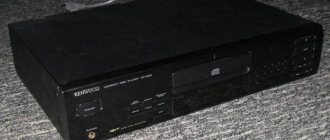
Before this, the setup used the Amfiton-U-002 UMZCH for several years, from which everything unnecessary was removed (switching, volume controls, timbres, etc., i.e., only the final PA was left). Therefore, the comparison is with this modified amplifier.
Amphiton-U-002 was disabled and moved to the side. Its place was taken by the modified Amfiton-U-101M (still without the top cover).
Assembled:
All adjustments on the front panel are a sham. ))
Subjectively, the Amphiton-U-101M is louder, with added highs. Fine (quiet) detail in the HF region has improved.
Compositions that are mixed by a competent sound engineer sound as they should, neutral. But the compositions with which the sound engineer cranked up the highs sound unusual.
To understand my subjective “measurements”, a measuring microphone was used. Moreover, in the house these microphones are like shoe polish.
About shoe polish.
Measurement microphones are available at olx.
The essence of the experiment: 1) the frequency response of the amplifier1-AS combination is taken in pink noise; 2) the frequency response of the amplifier2-AS combination is taken under the same conditions.
The results are AFC1 and AFC2 at the listening point. Then, frequency response1 is subtracted from frequency response2 (delta frequency response = frequency response2 minus frequency response1).
The meaning is simple: if frequency response 1 and frequency response 2 are the same, then subtraction results in a linear delta frequency response. Which is what was done. As usual, the SpectraLab program:
Here is the reason why the Amfiton-U-101M is a little louder: a rise of +4 dB in the 20 kHz region (relative to 1 kHz).
delta frequency response in table form
;deltaFR 20.000000 1.102917 22.400000 1.124969 25.000000 0.840706 28.000000 -0.523540 31.500000 1.905727 35.500000 -0.165012 40.00 0000 -3.232986 45.000000 -1.548897 50.000000 -1.245209 56.000000 -0.344727 63.000000 0.150932 71.000000 1.056561 80.000000 -0.6709 25 90.000000 1.210686 100.000000 0.850288 112.000000 1.448544 125.000000 2.625668 140.000000 0.174507 160.000000 0.273689 180 .000000 -0.801525 200.000000 -1.197544 224.000000 -0.526745 250.000000 -0.624901 280.000000 -1.174736 315.000000 0.940689 355.000000 0.828743 400 .000000 0.771759 450.000000 0.155586 500.000000 0.029461 560.000000 0.946098 630.000000 0.640984 710.000000 -0.228455 800.0000 00 1.206032 900.000000 1.034935 1000.000000 0.002937 1120.000000 -0.535984 1250.000000 -0.404110 1400.000000 -1.249935 1600.0000 00 0.293610 1800.000000 -0.399372 2000.000000 -1.136749 2240.000000 -0.245285 2500.000000 0.195511 2800.000000 0.044769 3150.000000 -0.251690 3550.000000 -0.408184 4000.0000 00 0.780884 4500.000000 0.255253 5000.000000 -0.155567 5600.000000 0.750320 6300.000000 -0.745819 7100.000000 -0.643879 8000.000 000 -0.572376 9000.000000 -0.796417 10000.000000 -0.346699 11200.000000 -0.497055 12500.000000 -0.358665 14000.000000 -0.595467 160 00.000000 - 0.286957 18000.000000 1.338181 20000.000000 3.746307 22400.000000 -3.135590
It’s strange, of course, that the rise at 20 kHz is so noticeable. I tested my hearing about 25 years ago; the upper limit was then determined to be about 16-17 kHz. A lot of water has passed under the bridge, you should double-check your hearing, fortunately the equipment at home allows this.
12. Conclusions:
— I like the sound quality of the converted amplifier; Personally, I don’t regret the time and effort spent - the rate of rise of the output voltage has been increased to 20 V/µs - a harmonic coefficient of 0.01% has been obtained
Happy experiments everyone!
Restoring the functionality of the full amplifier Amfiton-U-101-1 Stereo Hi-Fi
Amfiton-U-101-1, power amplifier
The amplifier was produced by the Lviv Lenin Production Association. The filling of this amplifier is almost 1:1 the same as the following models from the same company: - Amphiton-U-101, and varieties; — Amphiton A1-01, and varieties; — Amphiton 25u-101s; — Amphiton AJ-01-U.
General information is given here: https://rw6ase.narod.ru/000/rez2/amfiton_a1_01st.html
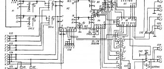
The scheme is a cross between the following schemes:
https://cp.people.overclockers.ru/cgi-bin/dl.pl?id=35407&filename=amfiton__101s.djvu
https://cp.people.overclockers.ru/cgi-bin/dl.pl?id=35406&filename=am_u101.djvu
Before updating GOST 24388-83, this amplifier was considered an amplifier of the highest complexity group.
According to information from the previous owner, this specimen had been in the closet for about 7 years, and before being put in the closet it was fully functional and had not undergone any repairs. Reality has made adjustments.
Even when purchasing, I noticed that it had obviously been opened. Upon closer examination, it was noticed that one output transistor and a heavily soldered transformer had been replaced before me. If everything is clear with the first one, then what they did with the transformer is not completely clear. I have only two options: - perhaps additional windings were connected to increase the supply voltages of the power amplifiers, and accordingly - increase the output power; — perhaps the transformer was completely changed, or one of the windings was rewound. I didn't notice any more signs of interference.
In this form, the amplifier turned on, the protection did not work (which was already pleasing), one channel worked, but played quietly, the second was silent.
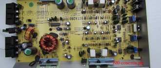
What I did in general: - replaced all electrolytic capacitors (polar and non-polar) with non-musical imported ones, in terms of power supply I replaced all 2200mF with 3300mF; — replaced all the red round film capacitors (the so-called “flags”, which often “rattling”, i.e. the capacitance floats) with modern imported ones; — replaced the output transistors: KT818GM with MJ2955, KT819GM with 2N3055; — replaced all 4 trimming resistors in the power amplifiers with multi-turn imported ones, adjusted the zero constant voltage at the outputs, and the quiescent current within 50-53 mA; — replaced the cord with a new one, with a larger cross-section and a Euro-style socket; — checked all ground connection points, soldered the broken solder contacts of the 5-pin DIN input signal sockets; — variable resistors for volume, balance and frequencies — I haven’t found them on the market yet, so I lubricated them with silicone and put them aside until better times.
Along the way, I rang the transistors that came to hand, mostly without soldering them; I rang the ones I soldered, checked the gain with a multimeter, and soldered them back (absolutely all transistors in the power amplifier units rang).
After the above steps, the device was assembled and turned on: - the second channel began to work; — the output sound power is fine (while I was repairing it I used 2 speakers of 8 Ohm, 0.5 W as a load), periodic crackling/wheezing/noise was heard; — “background” was heard in both channels; — voltage on power amplifiers is normal: 34V and 33.9V; — the constant voltage at the outputs of the left and right channels is normal: 0.04-0.05V each.
While I was setting up the quiescent current, I accidentally shorted two legs of a transistor in one of the PAs with a probe, which ultimately burned out one output transistor and one KT814 of the current amplifier node in the PA. There was little bloodshed. I restored the PA quite quickly, comparing it with the working channel.
Next, I accidentally shorted the output of one of the channels, the protection did not work - only one of the output transistors burned out.
The background and extraneous crackling disappears after the shielding cover is closed; it is mainly “caught” by the tone block board.
In general, in the end, I repaired the amplifier, set the constant voltage at the output to “0” (actually 0.0000V to 0.0040V), and adjusted the quiescent current to 50-53mA. There are no extraneous sounds to the ear at any volume (I listened to both music and test discs).
The quiescent current was set by the voltage drop across resistors R32 and R33 (in my case, 0.13 Ohm, 1 W). For those who don’t know how, I’ll describe the process: — don’t apply anything to the input, let the amplifier warm up; — set the multimeter to measure voltage in mV; - touch one terminal of the resistor with one probe, and the second with the second; — then, according to Ohm’s law, we set the required voltage using trimming resistor R18 (for example, 7 mV to get 7/0.13 = 53.85 mA).
The quiescent current from the factory is usually set to 40mA, but experts advise 50-100mA. If you tune it only by ear (in general, you should tune it using an oscilloscope, but not everyone has one) - it is necessary that the quiescent current be of such a magnitude that at low volumes no wheezing or extraneous sounds can be heard. You cannot go too far with the quiescent current value, otherwise you can burn out the PA, and keep in mind that when the amplifier warms up, the current must be checked, as it increases.
The zero voltage at the channel output is set using R5.
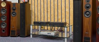
As a result, in comparison with the home Yamaha RX-V520 RDS receiver, I like the sound, there is sufficient detail, sharp and deep bass (noticeably more than on my receiver), the high frequencies are slightly raised, the background (“white noise”) is greater than that of the receiver, but insignificantly, it’s quite possible to put up with it, maybe over time I’ll try to reduce it. The volume and balance resistors also rustle, but this can be corrected over time.
The amplifier pleased with the sound quality, unpretentiousness and maintainability.
The plans include: — replacing variable resistors; — replace the power button; — replace the relay; — replace the wires.
UPDATE:
Initial capacitor values on scans:
Amfiton-U-101-1, tone block (capacitors)
Amfiton-U-101-1, pre-amplifier (capacitors)
Amphiton-U-101-1, operating mode block (capacitors)
Amfiton-U-101-1, protection unit (capacitors)
Amfiton-U-101-1, power amplifier (capacitors)
Note: 1) “+” indicates the location of the capacitor leg on the “+” board. 2) The absence of “+” means that the capacitor is non-polar.
Non-polar capacitors are found:
1) Pre-amplifier unit: - 2 pieces: 16V, 50mF
2) Protection unit: - 1 piece: 16V, 50mF
According to the wishes of the workers - photos in the process of repair:
Amphiton-U-101-1, photo in the process of repair
Amphiton-U-101-1, photo in the process of repair
Amphiton-U-101-1, photo in the process of repair
Amphiton-U-101-1, photo in the process of repair
For those wishing to discuss the article: https://forums.overclockers.ru/viewtopic.php?f=25&t=350340&sid=216e82ab35f1b8eca62a266423b86b13&start=140