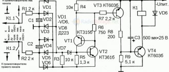
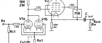
The laboratory power supply (LPS) presented in this article has a simple, but at the same time reliable and highly repeatable circuit. Bipolar transistors are used as the main components of the device. The LPS can be used for: testing power transistors, powering LEDs (LED panels), charging various types of batteries, powering electronic devices with a voltage of 0–40V and a current of up to 2.5A.
Output current stabilization is used as protection against short circuits of the laboratory power supply. The maximum current threshold can be set using a trimming resistor in the range of 0.5–2.5A. The load current is adjusted during operation from zero to a set threshold using a variable resistor.
The upper limit of the output voltage can also be set using a trimmer in the range of 10–40V. The output voltage is adjusted during operation using a variable resistor from zero to a set threshold.
⇡#Linear and switching power supplies
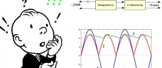
Let's start with the basics. The power supply in a computer performs three functions. First, alternating current from the household power supply must be converted to direct current. The second task of the power supply is to reduce the voltage of 110-230 V, which is excessive for computer electronics, to the standard values required by power converters of individual PC components - 12 V, 5 V and 3.3 V (as well as negative voltages, which we will talk about a little later) . Finally, the power supply plays the role of a voltage stabilizer.
There are two main types of power supplies that perform the above functions - linear and switching. The simplest linear power supply is based on a transformer, on which the alternating current voltage is reduced to the required value, and then the current is rectified by a diode bridge.
However, the power supply is also required to stabilize the output voltage, which is caused by both voltage instability in the household network and a voltage drop in response to an increase in current in the load.
To compensate for the voltage drop, in a linear power supply the transformer parameters are calculated to provide excess power. Then, at high current, the required voltage will be observed in the load. However, the increased voltage that will occur without any means of compensation at low current in the payload is also unacceptable. Excess voltage is eliminated by including a non-useful load in the circuit. In the simplest case, this is a resistor or transistor connected through a Zener diode. In a more advanced version, the transistor is controlled by a microcircuit with a comparator. Be that as it may, excess power is simply dissipated as heat, which negatively affects the efficiency of the device.
An example of a linear power supply with a stabilizer. Excess power is dissipated in transistor Q1
In the switching power supply circuit, one more variable appears, on which the output voltage depends, in addition to the two already existing: input voltage and load resistance. There is a switch in series with the load (which in the case we are interested in is a transistor), controlled by a microcontroller in pulse width modulation (PWM) mode. The higher the duration of the open states of the transistor in relation to their period (this parameter is called duty cycle, in Russian terminology the inverse value is used - duty cycle), the higher the output voltage. Due to the presence of a switch, a switching power supply is also called Switched-Mode Power Supply (SMPS).
No current flows through a closed transistor, and the resistance of an open transistor is ideally negligible. In reality, an open transistor has resistance and dissipates some of the power as heat. In addition, the transition between transistor states is not perfectly discrete. And yet, the efficiency of a pulsed current source can exceed 90%, while the efficiency of a linear power supply with a stabilizer reaches 50% at best.
The simplest circuit of an AC/DC pulse converter with a transformer
Another advantage of switching power supplies is the radical reduction in the size and weight of the transformer compared to linear power supplies of the same power. It is known that the higher the frequency of alternating current in the primary winding of a transformer, the smaller the required core size and the number of winding turns. Therefore, the key transistor in the circuit is placed not after, but before the transformer and, in addition to voltage stabilization, is used to produce high-frequency alternating current (for computer power supplies this is from 30 to 100 kHz and higher, and as a rule - about 60 kHz). A transformer operating at a power supply frequency of 50-60 Hz would be tens of times more massive for the power required by a standard computer.
Linear power supplies today are used mainly in the case of low-power applications, where the relatively complex electronics required for a switching power supply constitute a more sensitive cost item compared to a transformer. These are, for example, 9 V power supplies, which are used for guitar effects pedals, and once for game consoles, etc. But chargers for smartphones are already entirely pulsed - here the costs are justified. Due to the significantly lower amplitude of voltage ripple at the output, linear power supplies are also used in those areas where this quality is in demand.
Power
Based on the useful power supplied to the load, all laboratory DC power supplies can be divided into standard (up to 700 W) and high power (700 W or more). This division is not accidental. Standard and high power models differ quite significantly in functionality and application.
In standard power models, the maximum voltage is usually in the range from 15 V to 150 V, and the maximum current from 1 A to 25 A. Number of channels: one, two or three. There are both linear and impulse models. Design: standard instrument housing for placement on a laboratory bench. Weight from 2 to 15 kg. A typical example: the Tektronix PWS4000 series. Basically, the capabilities of such devices are aimed at the development and repair of electronic equipment, although the scope of their application is much wider.
On the other hand, high power models are always single-channel and pulsed. Models up to 3 kW are available in instrument or rack-mount versions (a typical example: ITECH IT6700H series), and models with a power of 3 kW and more powerful are mounted only in an industrial rack and are distinguished by significant weight and dimensions. For example, the weight of an 18 kW model from the ITECH IT6000C series is 40 kg.
High power places increased demands on the design: the presence of “smart” cooling fans, a full set of protections (against overload, overheating, polarity reversal, etc.), the ability to connect several units in parallel to increase output power, support for special forms of output signals (for example, automobile standards DIN40839 and ISO-16750-2).
For this category of devices, it is mandatory to support remote software control through one of the interfaces: Ethernet, IEEE-488.2 (GPIB), USB, RS-232, RS-485 or CAN, since they are often used as part of automated systems. Also, some series (for example IT6000C) can adjust their output resistance in the range from zero to several ohms, which is very useful when simulating the operation of batteries and solar panels. In addition, some high-power models may contain a built-in electronic load, which allows them not only to generate current, but also to consume it.
High power laboratory power supplies are used in the automotive industry, alternative energy, metal galvanic processing and many other industries where it is necessary to generate voltages up to 2,250 Volts and currents up to 2,040 Amps.
The characteristics of all laboratory power supplies, sorted by increasing maximum power, can be found here. And in this photo you can see the powerful output terminals of the six-kilowatt IT6533D model, which consists of two modules of 3 kW each, connected in parallel. Uniform distribution of output power between modules is ensured using a separate synchronization bus System BUS (gray cable on the left).
Part of the rear panel of an ITECH IT6533D laboratory power supply with a maximum power of 6 kW.
⇡#General diagram of an ATX power supply
A desktop computer's power supply is a switching power supply, the input of which is supplied with household voltage with parameters of 110/230 V, 50-60 Hz, and the output has a number of DC lines, the main ones of which are rated 12, 5 and 3.3 V In addition, the power supply provides a voltage of -12 V, and sometime also a voltage of -5 V, necessary for the ISA bus. But the latter was at some point excluded from the ATX standard due to the end of support for the ISA itself.
Block diagram of a pulse power supply
In the simplified diagram of a standard switching power supply presented above, four main stages can be distinguished. In the same order, we consider the components of power supplies in the reviews, namely:
- EMI filter – electromagnetic interference (RFI filter);
- primary circuit - input rectifier, key transistors (switcher), creating high-frequency alternating current on the primary winding of the transformer;
- main transformer;
- secondary circuit - current rectifiers from the secondary winding of the transformer (rectifiers), smoothing filters at the output (filtering).
Internal structure of the power supply unit (AeroCool KCAS-650M)
Complete circuit diagram of a simple ATX power supply
⇡#EMF filter
The filter at the power supply input is used to suppress two types of electromagnetic interference: differential (differential-mode) – when the interference current flows in different directions in the power lines, and common-mode (common-mode) – when the current flows in one direction.
Differential noise is suppressed by capacitor CX (the large yellow film capacitor in the photo above) connected in parallel with the load. Sometimes a choke is additionally attached to each wire, which performs the same function (not on the diagram).
The common mode filter is formed by CY capacitors (blue drop-shaped ceramic capacitors in the photo), connecting the power lines to ground at a common point, etc. a common-mode choke (LF1 in the diagram), the current in the two windings of which flows in the same direction, which creates resistance for common-mode interference.
EMI filter circuit
In cheap models, a minimum set of filter parts is installed; in more expensive ones, the described circuits form repeating (in whole or in part) links. In the past, it was not uncommon to see power supplies without any EMI filter at all. Now this is rather a curious exception, although if you buy a very cheap power supply, you can still run into such a surprise. As a result, not only and not so much the computer itself will suffer, but other equipment connected to the household network - switching power supplies are a powerful source of interference.
In the filter area of a good power supply, you can find several parts that protect the device itself or its owner from damage. There is almost always a simple fuse for short circuit protection (F1 in the diagram). Note that when the fuse trips, the protected object is no longer the power supply. If a short circuit occurs, it means that the key transistors have already broken through, and it is important to at least prevent the electrical wiring from catching fire. If a fuse in the power supply suddenly burns out, then replacing it with a new one is most likely pointless.
Separately, protection against short-term voltage surges is provided using a varistor (MOV - Metal Oxide Varistor). But there are no means of protection against prolonged voltage increases in computer power supplies. This function is performed by external stabilizers with their own transformer inside.
EMI filter (Antec VP700P)
The capacitor in the PFC circuit after the rectifier can retain a significant charge after being disconnected from power. To prevent a careless person who sticks his finger into the power connector from receiving an electric shock, a high-value discharge resistor (bleeder resistor) is installed between the wires. In a more sophisticated version - together with a control circuit that prevents charge from leaking when the device is operating.
By the way, the presence of a filter in the PC power supply (and the power supply of a monitor and almost any computer equipment also has one) means that buying a separate “surge filter” instead of a regular extension cord is, in general, pointless. Everything is the same inside him. The only condition in any case is normal three-pin wiring with grounding. Otherwise, the CY capacitors connected to ground simply will not be able to perform their function.
Additional information on this topic
We deliberately did not overload this article with technical details of the design of laboratory power supplies and a thorough description of their options. You can read all this in detail on the pages of individual series of devices. And to deeply understand this issue and improve your professional level, study documents on the basic theory of using laboratory power supplies.
If you need detailed pricing information or technical advice on choosing the optimal power supply for your application, just call us or email us and we will be happy to answer your questions.
⇡#Active PFC block
In an AC circuit with a linear load (such as an incandescent light bulb or an electric stove), the current flow follows the same sine wave as the voltage. But this is not the case with devices that have an input rectifier, such as switching power supplies. The power supply passes current in short pulses, approximately coinciding in time with the peaks of the voltage sine wave (that is, the maximum instantaneous voltage) when the smoothing capacitor of the rectifier is recharged.
Current consumption of a switching power supply
The distorted current signal is decomposed into several harmonic oscillations in the sum of a sinusoid of a given amplitude (the ideal signal that would occur with a linear load).
The power used to perform useful work (which, in fact, is heating the PC components) is indicated in the characteristics of the power supply and is called active. The remaining power generated by harmonic oscillations of the current is called reactive. It does not produce useful work, but heats the wires and creates a load on transformers and other power equipment.
The vector sum of reactive and active power is called apparent power. And the ratio of active power to total power is called power factor - not to be confused with efficiency!
A switching power supply initially has a rather low power factor - about 0.7. For a private consumer, reactive power is not a problem (fortunately, it is not taken into account by electricity meters), unless he uses a UPS. The uninterruptible power supply is responsible for the full power of the load. At the scale of an office or city network, excess reactive power created by switching power supplies already significantly reduces the quality of power supply and causes costs, so it is being actively combated.
Electrical diagram and current consumption of the Active PFC unit
In particular, the vast majority of computer power supplies are equipped with active power factor correction (Active PFC) circuits. A unit with an active PFC is easily identified by a single large capacitor and inductor installed after the rectifier. In essence, Active PFC is another pulse converter that maintains a constant charge on the capacitor with a voltage of about 400 V. In this case, current from the supply network is consumed in short pulses, the width of which is selected so that the signal is approximated by a sine wave - which is required to simulate a linear load . To synchronize the current consumption signal with the voltage sinusoid, the PFC controller has special logic.
The active PFC circuit contains one or two key transistors and a powerful diode, which are placed on the same heatsink with the key transistors of the main power supply converter. As a rule, the PWM controller of the main converter key and the Active PFC key are one chip (PWM/PFC Combo).
Active PFC block and input rectifier (Antec VP700P)
The power factor of switching power supplies with active PFC reaches 0.95 and higher. In addition, they have one additional advantage - they do not require a 110/230 V mains switch and a corresponding voltage doubler inside the power supply. Most PFC circuits handle voltages from 85 to 265 V. In addition, the sensitivity of the power supply to short-term voltage dips is reduced.
By the way, in addition to active PFC correction, there is also a passive one, which involves installing a high-inductance inductor in series with the load. Its efficiency is low, and you are unlikely to find this in a modern power supply.
⇡#Main converter
The general principle of operation for all pulse power supplies of an isolated topology (with a transformer) is the same: a key transistor (or transistors) creates alternating current on the primary winding of the transformer, and the PWM controller controls the duty cycle of their switching. Specific circuits, however, differ both in the number of key transistors and other elements, and in qualitative characteristics: efficiency, signal shape, noise, etc. But here too much depends on the specific implementation for this to be worth focusing on. For those interested, we provide a set of diagrams and a table that will allow you to identify them in specific devices based on the composition of the parts.
| Transistors | Diodes | Capacitors | Transformer primary legs | |
| Single-Transistor Forward | 1 | 1 | 1 | 4 |
| Two-Transistor Forward | 2 | 2 | 0 | 2 |
| Half Bridge | 2 | 0 | 2 | 2 |
| Full Bridge | 4 | 0 | 0 | 2 |
| Push-Pull | 2 | 0 | 0 | 3 |
In addition to the listed topologies, in expensive power supplies there are resonant versions of Half Bridge, which are easily identified by an additional large inductor (or two) and a capacitor forming an oscillatory circuit.
| Single-Transistor Forward | Two-Transistor Forward | Push-Pull |
| Full Bridge | Half Bridge | Resonant Half-Bridge |
Video
Coffee capsules Nescafe Dolce Gusto Cappuccino, 8 servings (16 capsules)
435 ₽ More details
Coffee capsule Nescafe Dolce Gusto Cafe O Le Coffee with milk, 3 packs of 16 capsules each
1305 ₽ More details
External sound cards
⇡#Secondary circuit
The secondary circuit is everything that comes after the secondary winding of the transformer. In most modern power supplies, the transformer has two windings: 12 V is removed from one of them, and 5 V from the other. The current is first rectified using an assembly of two Schottky diodes - one or several per bus (on the highest loaded bus - 12 V - in powerful power supplies there are four assemblies). More efficient in terms of efficiency are synchronous rectifiers, which use field-effect transistors instead of diodes. But this is the prerogative of truly advanced and expensive power supplies that claim the 80 PLUS Platinum certificate.
The 3.3V rail is typically driven from the same winding as the 5V rail, only the voltage is stepped down using a saturable inductor (Mag Amp). A special winding on a transformer for a voltage of 3.3 V is an exotic option. Of the negative voltages in the current ATX standard, only -12 V remains, which is removed from the secondary winding under the 12 V bus through separate low-current diodes.
PWM control of the converter key changes the voltage on the primary winding of the transformer, and therefore on all secondary windings at once. At the same time, the computer's current consumption is by no means evenly distributed between the power supply buses. In modern hardware, the most loaded bus is 12-V.
To separately stabilize voltages on different buses, additional measures are required. The classic method involves using a group stabilization choke. Three main buses are passed through its windings, and as a result, if the current increases on one bus, the voltage drops on the others. Let's say the current on the 12 V bus has increased, and in order to prevent a voltage drop, the PWM controller has reduced the duty cycle of the key transistors. As a result, the voltage on the 5 V bus could go beyond the permissible limits, but was suppressed by the group stabilization choke.
The voltage on the 3.3 V bus is additionally regulated by another saturable inductor.
Stabilizing chokes and output filter (Antec VP700P)
A more advanced version provides separate stabilization of the 5 and 12 V buses due to saturable chokes, but now this design has given way to DC-DC converters in expensive high-quality power supplies. In the latter case, the transformer has a single secondary winding with a voltage of 12 V, and the voltages of 5 V and 3.3 V are obtained thanks to DC-DC converters. This method is most favorable for voltage stability.
DC-DC converter for 5 V bus (CoolerMaster G650M)
Output filter
The final stage on each bus is a filter that smoothes out voltage ripple caused by the key transistors. In addition, the pulsations of the input rectifier, whose frequency is equal to twice the frequency of the supply network, penetrate to one degree or another into the secondary circuit of the power supply.
The ripple filter includes a choke and large capacitors. High-quality power supplies are characterized by a capacitance of at least 2,000 uF, but manufacturers of cheap models have reserves for savings when they install capacitors, for example, of half the nominal value, which inevitably affects the ripple amplitude.
How to select components
For a transformer source, first of all, a transformer is selected. In most cases, it is taken ready-made from what is available. This node must produce the required current at maximum voltage. The combination of these parameters is ensured by the overall power of the transformer. For industrial devices, parameters can be found in the reference book. For random transformers, the power can be determined by the core dimensions (in centimeters).
Core area for different types of transformers.
Power is calculated using the formula:
P=S2/1.44 where:
- P-power in Watts;
- S is the cross section in square centimeters.
For practical purposes, the power must also be multiplied by the efficiency. For example, a transformer with a core area of 6 sq.cm. at a voltage of 35 volts and a stabilizer output voltage of 30 volts (the overall efficiency can be taken as 0.75) it is capable of delivering power P=(36/1.44)*0.75=18.75 watts. The maximum current will be I=P/U=18.75/35=0.5 A.
If the transformer passes power, but the secondary winding is designed for a different voltage, it can be removed and a new one wound (if it fits). The number of turns is calculated as follows:
- the number of turns per volt is determined by the formula 50/S, where S is the core area in sq.cm;
- this value is multiplied by the required voltage level.
So, for an area of 6 cm per 1 volt there are 50/6 = 8.3 turns per volt. For a voltage of 35 volts, the winding must have 35 * 8.3 = 291 turns. The wire diameter is calculated using the formula D=0.02, where I is the current in milliamps. For a current of 5 amperes, you need to take a wire with a diameter of 0.02 * = 70 * 0.02 = 1.4 mm.
If a high-power transistor is selected for a linear regulator, the main criterion for application is the collector current. It must cover the load current with a margin. This parameter for common domestic and foreign transistors is given in the table.
| Transistor | Maximum collector current (constant), A |
| KT818 (819) | 10 |
| KT825 (827) | 20 |
| KT805 | 5 |
| TIP36 | 25 |
| 2N3055 | 15 |
| MJE13009 | 12 |
When operating in modes close to the maximum current, transistors must be installed on radiators.
You also need to pay attention to such a parameter as the maximum voltage between the collector and emitter. With an input voltage of 35 volts and an output voltage of 1.5, the difference will be 33.5 volts; for some semiconductor devices this is unacceptable.
The capacity of the oxide capacitor located after the rectifier is selected based on the load. There are formulas for calculating filter parameters, but in practice the approach is simple: the more, the better. There are two restrictions imposed on the capacity:
- capacitor dimensions;
- inrush current per charge, which can be significant with a large capacity.
The output capacitor of the power supply can have a capacity of about 1000 µF.
⇡#Standby power supply +5VSB
A description of the components of the power supply would be incomplete without mentioning the 5 V standby voltage source, which makes the PC sleep mode possible and ensures the operation of all devices that must be turned on at all times. The “duty room” is powered by a separate pulse converter with a low-power transformer. In some power supplies, there is also a third transformer, which is used in the feedback circuit to isolate the PWM controller from the primary circuit of the main converter. In other cases, this function is performed by optocouplers (an LED and a phototransistor in one package).
Transformers (Corsair HX750i)