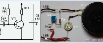
Measuring the output power of a low-frequency amplifier
In this article I will try to tell you how to objectively measure the output power of a bass amplifier. For measurements we need an oscilloscope and a low-frequency signal generator. To my regret, without these devices it is impossible to objectively measure. The sound generator can be replaced by a computer or laptop with software installed on it.
The “Generators” section contains several free programs that will allow you to turn your laptop or PC into a signal generator.
So, we need an oscilloscope, a sinusoidal signal generator, a resistor (equivalent) with a resistance of 4 Ohms, the amplifier itself and, if possible (optional), a multimeter.
As a “donkey” I use my favorite single-channel device S1-94. My generator is a Chinese function generator, capable of generating various waveforms with adjustable frequency, amplitude and offset.
The load will be a resistor with a resistance of 4 Ohms and a power of 100 W. For reliability, I installed it on a radiator using heat-conducting paste.
Now about the multimeter. Not everyone will do. It should correctly measure AC voltage at a frequency of 1000Hz-2000Hz. If it is not there, then you can do without it. I am using UNI-T UT39C.
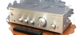
I will measure the power on the Elegia-102-stereo radio amplifier.
Before measuring the output power, it is necessary to run the amplifier at moderate power for 10-20 minutes.
I applied a signal from the generator to the input for connecting the tape recorder. You may have this as a “Universal”, “Tuner” or other line input. The signal must be a sinusoidal waveform with a frequency of 1000Hz. The amplitude on the generator must be set to zero.
Next, you need to turn the volume control knobs to maximum, and the tone and balance controls to the middle.
We connect a load in the form of a resistor with a resistance of 4 Ohms to the output of the amplifier, in the speaker system connection socket. The resistor must be lowered into water or installed on a radiator.
You need to install the probes of an oscilloscope and a multimeter in parallel with the resistor. On the oscilloscope, select the required sweep. In my case it is 0.2ms per cell and 5V per cell.
Turn on the power to the amplifier. Turn on the generator and oscilloscope.
We smoothly increase the amplitude of the signal on the generator and look at its shape on the oscilloscope screen.
The shape should be clean, sinusoidal. As the amplitude increases (on the generator), it is necessary to catch the moment when the top of the sine wave begins to be cut off. This phenomenon is called clipping.
After clipping appears, it is necessary to slightly reduce the amplitude until a pure sinusoid appears.
Now the bass amplifier is operating at maximum (clean) power.
Now you need to measure the voltage across the load resistor and, as they say: “It’s in the bag!”
You can measure voltage with a multimeter, which does not “lie” when measured at a frequency of 1 kHz, or using an oscilloscope. I will measure with both this and that.
On the multimeter display my AC voltage was 7.5V.
On the oscilloscope screen I see the sine wave swing (or double amplitude) of 4.2 cells. One cell 5V. Total, double amplitude is 21V. As we know, the swing is 2–2 times greater than the effective voltage value. Therefore, we divide 21V by 2?2.
21V/2.83=7.4V. Does it fit? It fits!
Output power calculation
Power is calculated by the formula P=U*I, where P is power, U is the voltage across the resistor, I is the current flowing through the resistor.
It is not necessary to measure current as it is known from Ohm’s law that I=U/R,
then P = U 2 / R .
We square the voltage we measured across the load resistor and divide by 4 Ohms.
P=7.5*7.5/4= 56.25/4 = 14W.
According to the operating instructions for Elegy-102-stereo, the rated output power for each channel is 6W, and the maximum power is 16W (for each channel).
Thank you for your attention!
Amplifier classification
All amplifiers can be classified according to the following criteria:
By frequency of the amplified signal:
- low frequency amplifiers (LF) for amplifying signals from tens of hertz to tens or hundreds of kilohertz;
- broadband amplifiers that amplify signals of units and tens of megahertz;
- selective amplifiers that amplify signals of a narrow frequency band;
By type of signal being amplified
- DC amplifiers (DCA), amplifying electrical signals with a frequency of zero hertz and higher;
- AC amplifiers that amplify electrical signals with a frequency other than zero;
By functional purpose
- voltage amplifiers, current amplifiers and power amplifiers depending on which parameter the amplifier amplifies. The main quantitative parameter of the amplifier is the gain.
Depending on the functional purpose of the amplifier, amplification factors are distinguished by voltage KU, current Ki or power KR:
КU = Uin / Uout
КI= Iin/ Iout
КP= Pin / Pout
where Uin, Iin are the amplitude values of the variable components of voltage and current at the input, respectively;
Uout, Iout are the amplitude values of the alternating components of the voltage and current at the output, respectively;
Rin, Rout - signal powers at the input and output, respectively. Gain factors are often expressed in logarithmic units - decibels:
KU (dB) = 20LgKu
KI(dB) = 20LgKi
KR (dB) = 10LgKp
An amplifier may consist of one or more stages. For multistage amplifiers, its gain is equal to the product of the gains of its individual stages: K = K1 K2 ... Kn
If the gains of the stages are expressed in decibels, then the total gain is equal to the sum of the gains of the individual stages:
K (dB) = K1 (dB) + K2 (dB) +... + Kn (dB).
Typically, the amplifier contains reactive elements, including “parasitic” ones, and the amplification elements used have inertia. Because of this, the gain is a complex quantity:
ЌU = КU ejφ
КU = Uout / Uin
where KU is the gain module; φ is the phase shift between the input and output voltages with amplitudes Uin and Uout.
In addition to the gain, an important quantitative indicator is the efficiency:
η = Pout / Pist
where Rist is the power consumed by the amplifier from the power source.
The role of this indicator especially increases for powerful, as a rule, output stages of the amplifier.
Quantitative indicators of the amplifier also include the input Rin and output Rout resistance of the amplifier:
Rin = Uin / Iin
Rout = |∆ Uout | / |∆ Iout |
where Uin and Iin are the amplitude values of voltage and current at the amplifier input;
∆Uout and ∆Iout are increments in the amplitude values of voltage and current at the amplifier output caused by changes in load resistance. Let us now consider the main characteristics of amplifiers.
Watch an interesting video about the amplifier parameters below:
Amplifier amplitude response
The amplitude characteristic is the dependence of the amplitude of the output voltage (current) on the amplitude of the input voltage (current) (Fig. 2.2).
Point 1 corresponds to the noise voltage measured at Uвx = 0, point 2 corresponds to the minimum input voltage at which the signal can be distinguished from the background noise at the amplifier output.
Section 2 - 3 is the working section in which the proportionality between the input and output voltages of the amplifier is maintained.
After point 3, nonlinear distortions of the input signal are observed. The degree of nonlinear distortion is estimated by the nonlinear distortion factor (or harmonic distortion):
KG = √(U22m + U23m + … + U2nm) / Ulm
where Ulm, U2m, U3m, Unm are the amplitudes of the 1st (fundamental), 2nd, 3rd and nth harmonics of the output voltage, respectively. The value D = Uin max / Uin min characterizes the dynamic range of the amplifier. Let's consider an example of the occurrence of nonlinear distortions (Fig. 2.3).
When a sinusoidal voltage ube is applied to the base of the transistor relative to the emitter, due to the nonlinearity of the input characteristic of the transistor ib = f(ube), the input current of the transistor ib (and therefore the output - collector current) is different from the sinusoid, i.e. a number of higher values appear in it harmonics
From the above example it is clear that nonlinear distortions depend on the amplitude of the input signal and the position of the operating point of the transistor and are not related to the frequency of the input signal, i.e., to reduce the distortion of the output signal shape, the input signal must be low-level.
Therefore, in multistage amplifiers, nonlinear distortions mainly appear in the final stages, the input of which receives signals with large amplitude.
News
Date: 0000-00-00Conversation accidentally overheard in the parking lot: “Do you have an amplifier?”
-Well.
-What the hell. Which one then?
-Four pieces. Fifty watts. - A little weak... I have four of them! And all for seventy-five!
-Cool, though!
-And then!
To be honest, what prompted me to write this article was the general illiteracy of those who sell audio equipment, and it sometimes goes beyond all boundaries. It happens that people advising you to choose this or that product are well versed in the functionality of the devices, they can memorize all the indicators that are in the instructions, but, unfortunately, only a few have a good idea of what these numbers mean. It’s not even worth mentioning that they can competently explain their essence to the client (on the other hand, they can always give advice on buying the coolest device). Naturally, it would be unfair to brand everyone with the same brush, but exceptions, unfortunately, are becoming increasingly rare.
Although, these are emotions (it’s boiling, sorry). Of course, I do not urge you all to sit down right now with specialized literature and take an exam in the subject: “Theories of Electric Circuits.” But knowing even the most simple things, you can well protect yourself from bad or unqualified advice when buying equipment.
First, you need to decide what amplifier power is in general, and how it is measured in general. Where do these Watts come from, and can an amplifier on which, for example, “75 W” is written, be much more powerful than an amplifier on which the number “100 W” is emblazoned. If we look ahead a little, we can say that it can. But let's take our time and tell you about everything in order.
PHYSICAL PROCESS
Remembering our school physics lessons, we know that electrical power is the work of transferring an electric charge per unit time. This definition doesn’t give us much, despite its accuracy, so let’s try to develop it further. Let's remember that work is the measure by which energy changes. In our version, power is a measure of how much electrical energy the amplifier will deliver to the load per unit of time.
Everything seems to be clear with this. Now let's decide what it depends on. In general cases, instantaneous power (the power that the amplifier produces at a single moment in time) depends on two indicators: what voltage the amplifier will create under the load at this moment, and what current flows through it:
It is also possible to connect a wide variety of speaker systems to the amplifier. And they will be a difficult complex burden for her. In this case, the current and voltage will be out of phase (that’s right, don’t say you weren’t taught this at school). It is clearly shown in Figure 1.
I wonder what this part of the graph means, where the power is negative? At such moments in time, the speaker system (sound system) returns part of the energy back to the amplifier, like an electric motor that becomes a generator in braking mode.
But there are still many different speakers, and they all have different parameters at their disposal - not only will they have a different phase shift between current and voltage, and also have their own at each frequency. Does this mean that the amplifier will produce its own specific power for each speaker? Like so. But how can we define it unambiguously?
Firstly, the concept of instantaneous power is somewhat inconvenient, because it is a variable quantity. Typically, the average power value (Ravg) is used. Secondly, instead of an AC, you can take a regular resistor for measurement. It has neither capacitance nor inductance, so the voltage and current in it will always be in phase (Figure 2). That’s what it’s called: resistive load equivalent.
In this case, without unnecessary corrections for phase shifts, we can determine the average power using the formula below:
P = I x U,
where I and U are the rms values of voltage and current. For a sinusoidal signal (this is what is used in measurements), they will be equal:
They are also called effective or effective values, which, in principle, can be the same thing. The physical meaning of the rms (effective, effective) power value of an alternating current looks like this: this is the value of force for alternating current that will produce the same electrodynamic or thermal effect as the same value of direct current. Also for tension.
The very concept of “root mean square” can only be applied to current or voltage, but you can often hear about root mean square power, although this, to be honest, is incorrect. For RMS power, the abbreviation will have a completely different meaning, and it is often associated with distortion levels, but we will talk about this a little later.
Remembering Ohm's law, we can transform the power formula into the most convenient formula for us:
P = U2/R,
R - load resistance (resistance of the resistor that was connected to the amplifier instead of the speakers). Thus, at the output, the signal power will depend mainly on two factors: the voltage of the output signal, as well as the resistance of the load connected to it.
BY THE WAY:
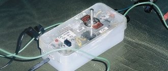
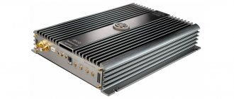
Last year, for CarMusic magazine, a monstrous amplifier was tested that was capable of developing enormous power. It was intended primarily for SPL (sound pressure competition) fighters. Think about it: in order for the amplifier to develop such hurricane-force power, a power supply had to be specially designed for it. It has eight toroidal (donut-shaped) transformers, around them, in two rows, there are input smoothing capacitors, another group of capacitors is the output smoothing. The increased voltage, after them, is supplied directly from the power supply to the circuit, where the signal is amplified. 12 Volts are also supplied appropriately: there are no unnecessary terminals, and the power cables go directly to the power buses. Please note that the part of the circuit where the signal is amplified takes up only a third of the long, almost meter-long housing. And everything else is a power supply that converts 12 Volts into a higher voltage.
POWER MAXIMUM
Let's go back a little to our amplifiers.
“Stop!” - the attentive reader will exclaim. - How can we get a signal with such huge hundreds of watts at the output of an amplifier that is powered by only 12 Volts, if this power develops, for example, at a load of 4 Ohms? It is also necessary to take into account the non-ideal efficiency of the amplifier. She can’t be like that!”
There is no error here. Any car amplifier will contain a power supply. His task is simple: you need to convert 12 Volts to 30, 50 Volts. So the amplifier circuit will be powered not by 12 Volts, but by 30, 50 or however many Volts we need. It comes out and the signal power at the output will be appropriate.
Maximum power is measured as follows. By increasing the signal level, wait until its amplitude limitation at the input begins. This will mean that the amplifier has finally reached the desired limit of its capabilities. The power that will be output is taken as the maximum.
One more thing needs to be mentioned here: the concept of maximum power can often be interpreted in different ways. Some manufacturers understand this as the average or normal power produced by the amplifier, while others understand the peak power value. An example of this: head units. There are no power supplies that increase the voltage, but they, however, often have inscriptions about the maximum output power. For example: 40, 50 W per channel.
Let's try to figure out these numbers. The maximum voltage amplitude at the signal output of an amplifier with a 12-volt power supply can only be 6 Volts (the signal, after all, also has two half-waves). Then the root mean square value of the voltage of the sinusoidal signal at such an amplitude will be equal to
0.707 x 6 = 4.242 V
This means the maximum power will be:
4.2422/4 = 4.5 W
It turns out that the 50 Watt inscription is not true? Of course not, but this could not have happened without a little cunning on the part of the manufacturers. Firstly, amplifiers for head units are made as bridge amplifiers. This means that two amplifiers are simultaneously driving one speaker (in order to organize 4 outputs for the speakers, an 8-channel amplifier is made in the radio). So the power at the load is increased by 4 times. The maximum power of a sinusoidal signal can be approximately 18 W (by the way, the most truthful manufacturers, as a rule, still indicate it in the instructions). That's already something. Secondly, amplifiers built into head units are usually made according to circuits with a voltage boost (or class “H”). In other words, they have a capacitor, and it charges precisely at those moments when the signal is not yet very powerful, and then, when the signal peaks, it releases the accumulated energy. At such short moments of time, when the capacitor is charged, the amplifier is capable of delivering 40 or 50 W to the load. In other words, we are not talking about a sinusoidal signal, but about a musical or real one. Naturally, the spare energy will not be enough for the amplifier to reproduce the signal peak without distortion and the desired figure to be obtained. However, at the same time, it is silent about exactly how. Another thing is important: the indicated 45 or 50 W is not at all the maximum power produced by the head unit amplifier over a long period of time, but only the maximum produced by the amplifier at short moments of time, at signal peaks.
The voltage in the power supply of the on-board network itself when the measurements took place will also play a big role in the measurements. Suppose the power supply of the amplifier itself turns out to be stabilized, which is not found in all models, then 12.5 or, for example, 14 Volts will be supplied, this will not play a big role. But most amplifiers have unstabilized power supplies and their power ratings will directly depend on what they are actually powered by. In other words, with a high voltage in the on-board network, the amplifiers can provide a larger swing in the output signal voltage, hence the power will be higher. Therefore, normal manufacturers, as a rule, indicate the supply voltage when the measurements took place.
MINIMUM RESISTANCE
Suppose the range of signals at the output of the amplifier has already reached its limit, and we want more and more power, then we have only one thing left to do - reduce the load resistance. For example, you can connect a 2-ohm one instead of a 4-ohm one. In this case, the supply voltage will resist half as much, which means twice the current will flow through it. Therefore, the power will double.
But that's what it sounds like in theory. In practice, everything may depend on the capabilities of the circuit: there will be losses in the power supply, as well as in the amplifier itself. Such elements have far from enormous capabilities, and they are designed for strictly defined currents, and if overused they can easily burn out. Therefore, instructions often indicate the minimum load resistance: if it is indicated that, for example, it is 4 ohms, then if you connect 2-ohm speaker systems, the amplifier may fail. Modern amplifiers are most often designed for 2-ohm loads. A good indicator would be an increase in power output when moving from 4 Ohms to 2 Ohms by 60-80%. If you lower the resistance, the increase in power will be only 20-30%, which means that the amplifier will operate at the limit of its current capabilities and will not provide the necessary reserve.
NOMINAL POWER
In a word, maximum power well characterizes the power capabilities of the amplifier itself, but does not tell us anything about the quality of playback itself. If the amplifier reaches its limit, the signal will begin to distort (this is called clipping). That is, the amplifier will work well only when the output signal power is relatively low, and when it increases, the nonlinear distortion factor will increase sharply. See picture No. 3
Therefore, in addition to the maximum power, you also need to know the power where the distortions have not yet reached acceptable values. This is how you can determine the rated power of an amplifier. What the “permissible amount of distortion” means, each manufacturer can understand in its own way. For example, there are two models on one counter. Both say they have 50 watts per channel. But the first one indicates that it develops with distortions, for example, 0.01%, and the second one 1%. It is clear that the first amplifier will have a higher potential than the second, although the same number is indicated for both amplifiers.
In order to compare the power of amplifiers with each other, it has become possible, general standards for its measurement are periodically introduced. Both the IEC and GOST, and the German DIN had a lot to do with this. The most recent, CEA-2006, was published in 2003. According to this standard, power ratings must be measured in Watts RMS and determined using a 14.4 V power supply.
If the CEA-2006 logo is on the package with the amplifier, then rest assured that the output power was measured precisely according to these parameters, even if this was not specifically noted in the description.
But we must keep in mind that this is only one of the latest standards that have been adopted. Therefore, it is necessary to pay attention not only to these same power figures, but also to the conditions under which it was measured.
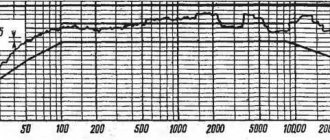
Amplitude-frequency response (AFC) and phase-frequency response (PFC) of the amplifier.
The frequency response is the dependence of the gain modulus on frequency, and the phase response is the dependence of the phase angle between the input and output voltages on frequency. A typical frequency response is shown in Fig. 2.4.
The frequencies fн and fв are called the lower and upper limit frequencies, and their difference (fн - fв) is the amplifier bandwidth.
When a harmonic signal of sufficiently small amplitude is amplified, distortion of the shape of the amplified signal does not occur.
When a complex input signal containing a number of harmonics is amplified, the harmonics are amplified unequally by the amplifier because the circuit reactances vary with frequency, resulting in a distorted waveform of the amplified signal.
Such distortions are called frequency distortions and are characterized by the frequency distortion coefficient: M = K0 / Kf where Kf is the modulus of the amplifier gain at a given frequency.
Frequency distortion coefficients МН = K0 / KН and МВ = K0 / KВ are called distortion coefficients at the lower and upper limit frequencies, respectively. The frequency response can also be plotted on a logarithmic scale. In this case, it is called LFC (Fig. 2.5), the gain of the amplifier is expressed in decibels, and frequencies are plotted along the abscissa axis through a decade (frequency interval between 10f and f).
f = 10n are chosen as reference points . The LFC curves have a certain slope in each frequency region. It is measured in decibels per decade. A typical phase response is shown in Fig. 2.6. It can also be plotted on a logarithmic scale. In the mid-frequency region, additional phase distortion is minimal.
The phase response makes it possible to evaluate phase distortions that arise in amplifiers for the same reasons as frequency distortions.
An example of the occurrence of phase distortions is shown in Fig. 2.7, which shows the amplification of an input signal consisting of two harmonics (dotted line), which undergo phase shifts when amplified.