In ordinary telephones, instead of carbon microphones, they now begin to use electret microphones, designed in a housing that imitates the body of a carbon microphone, which allows replacement without any problems in any phone.
Once the author had to repair a “TELTA” telephone set, which had an MKE-395-2 “Eltis” electret microphone installed. The appearance of the microphone is shown in Fig. 1.
The frequency characteristics of such a microphone, compared to a carbon microphone, are much better, the volume is comparable to a carbon one, although the volume was expected to be higher.
Rice. 1. Appearance of the microphone.
Amplifier circuit options
In another article, the same author proposed a ready-made preamplifier for a microphone.
This is an AGC (Automatic Gain Control) circuit. This is what this circuit looks like in the original (without a frequency correction circuit): Thanks to the use of a field-effect transistor (KP303Zh) in feedback, this circuit works as a compressor and equalizes the volume of the voice, changing the gain within certain limits.
The circuit is fully working, I personally tested it on a prototype and did not cause any problems. This design is very convenient, for example, for microphones in conference rooms and meeting rooms. But it can also be used as a preamplifier for a microphone when connected to a computer.
Therefore, the AGC had to be abandoned and the circuit was cut down to a conventional non-inverting amplifier with a constant gain. This scheme also copes with its responsibilities perfectly.
Questions
What is a microphone's polar pattern? A microphone's polar pattern is a way of representing the directionality of a microphone. In other words, polar patterns describe the directions in which the microphone is most sensitive, rental sensitive, and all points in between. Polar charts can be qualitative (with specific names) or quantitative (with polar response charts).
For a more in-depth look at microphone polar patterns, read my article, The Ultimate Guide to Microphone Polar Patterns.
What happens if the speaker is connected with reverse polarity? Connecting a speaker with reverse polarity will not damage the speaker, but will likely have a negative impact on playback. Transitional information can be lost when the speaker moves inward rather than outward. When two or more speakers are connected in reverse polarity, major phase compensation problems arise.
Problem
Most cheap microphones don't have a default sensitivity enough to be heard clearly. You have to scream, but you can’t do that on a regular basis; yelling is a tiresome and harmful activity.
Having carefully studied the issue, I came to the conclusion that the manufacturers are to blame for the situation, overly simplifying the design of the device. Having given his hard-earned 100-500 rubles, the buyer essentially receives a module (capsule) of an electret microphone without any electronic “piping”.
Electret microphone and standard 3.5 mm jack. This design does not allow the microphone to be sensitive, but you can record sound
All sorts of flexible legs and clothespins are optional tinsel. Formally, such microphones work, but their sensitivity and recording quality are low (noise is heard). There's nothing stopping you from adding a few electronic components to the circuit to improve the microphone's ability to pick up quiet sounds.
A typical representative of electret microphones
Here and further we will talk about electret microphones, as the most affordable on the market. And, partly, capacitors. Not dynamic!
I'm also not considering purchasing a separate sound card. This was already in the article “How to set up a microphone, record and process sound - instructions for beginners.”
Dynamic microphones already have a built-in amplifier
Amplifier circuits are quite simple, so people who know how to use a soldering iron remake microphones and enjoy life.
By the way, even cheap buttonholes for 100 rubles include good electret modules. For example, I have a Genius clip-on microphone from ten years ago, it works great. After modifications, of course.
In addition to low sensitivity, you can hear a low hiss on the recordings. It can be suppressed by filters in an audio editor, but when the interference is too strong, removing noise will distort the useful part of the recording and the voice will sound dull, as if from a barrel.
Noise (in 99% of cases this is interference from electromagnetic fields) appears at several stages of sound delivery:
- In the electret capsule of the microphone.
- In the microphone preamp, if available.
- When transmitting a signal via a connecting cable that is not shielded from interference.
- In the sound card amplifier.
The most painful place is the computer's sound card. Replacing with a better one and/or moving it outside the computer case can get rid of the noise, but not everyone has the money for such an upgrade.
Most often, the user is left alone with a cheap microphone plugged into a loud hissing sound card soldered to the computer motherboard. You can try to make the sound louder programmatically.
In-phase vs. Out of phase
Now let's discuss phase relationships with microphones. Phase is a little more complicated than polarity.
Phase refers to the amount of time a wave has gone through its cycle. Since sound and microphone signals are waves, phase is important. Two identical waves/in-phase signals are added, while two identical waves/in-phase signals cancel each other.
Phase usually applies to signals of the same frequency. If these waves are in phase, they line up along their entire shape. If they are out of phase, there will always be a difference between the two cycles at any given time.
However, audible sound and sound have a frequency range of 20 Hz. - 20000 Hz. For audio or sound to be truly 100% in phase is almost impossible unless we dub the audio digitally or use synthesizers.
By their nature, sound and acoustics have a very complex relationship, and even a pair of microphones placed very close to each other will not be 100% in phase. In doing so, we can get close to being in phase, and that is good enough for us (outside the ears, it is rare, if ever, to hear a sound that is perfectly in phase.
There are two main reasons why sound at two or more points is almost never in phase by nature:
- Direct distance from sound source: A sound wave will have different phases of its waveform at different distances from the sound source.
- Sound consists of many different frequencies: even if two microphones are located at the same distance from the sound source, the probability of matching all frequencies is almost zero. This is especially true for higher and more directional frequencies.
There are many other ways in which the sound will be different at two different microphone placements. This includes reflections/reverberation, other sound sources, and microphone direction.
So phase only really matters when there are two or more signals. Thus, microphone placement is critical to phase coherence when using more than one microphone.
Preamplifier for electret microphone with three transistors
This is another microphone amplifier option for an electret microphone. The peculiarity of this microphone amplifier circuit is that power is supplied to the preamplifier circuit through the same conductor (phantom power) through which the input signal travels.
This microphone preamplifier is designed to work together with an electret microphone, for example, MKE-3. The supply voltage to the microphone goes through resistance R1. The audio signal from the microphone output is supplied to the VT1 base through capacitor C1. A voltage divider consisting of resistances R2, R3 creates the necessary bias at the base of VT1 (approximately 0.6 V). The amplified signal from resistor R5, acting as a load, goes to the base of VT2 which is part of the emitter follower on VT2 and VT3.
Near the output connector, two additional elements are installed: load resistor R6, through which power is supplied, and separating capacitor SZ, which separates the output audio signal from the supply voltage.
The most interesting videos on Youtube
Related topics.
How to make a simple directional stereo microphone from junk?
Homemade microphone for recording videos on a digital camera.
A simple DIY microphone amplifier for your computer.
How to solder a plug to a shielded audio cable.
I’ll explain about “inoperability”. In the microphone I bought, instead of a shielded cable, it turned out to be a regular two-wire round cable. Of course, with such a cable the microphone was completely inoperable, since the background noise was comparable to the signal level.
How to make a microphone preamp with your own hands
Using a suitable circuit, assembling the device will not be difficult.
Tools and materials
Tools used in the work:
- soldering iron;
- wire cutters;
- scissors;
- tweezers;
- glue gun
In addition, you will need:
- radio components - LED, 2 resistors 200-600 Ohm, 2 capacitors with a capacity of up to 10 μF, transistor KT315 (can be replaced with KT3102 or BC847);
- wires;
- plug and connectors from an old tape recorder, DVD player or other equipment;
- switch from a toy car;
- solder and rosin;
- bread board.
Step-by-step instruction
They start by choosing a scheme. For a beginner, the simplest option is suitable, based on a transistor cascade with a common emitter. It amplifies the microphone signal by 2 times.
Sequencing:
- The breadboard is washed with solvent.
- Solder connectors to it - power supply, microphone input and output.
- The radio components are soldered onto the board according to the diagram.
- A case is made from a plastic box by drilling holes for connectors with a “wood” drill.
- The board is glued into the case or screwed with screws if there are threaded stands.
- Glue the housing cover.
- Connect the preamplifier to the computer sound card or speaker, then check the voltage at the microphone input. It should be 5 V.
If the voltage is different, take another plug and connect it to the connector. Next, check the voltage again between the long terminal and each of the 2 short ones. The multimeter probes are positioned so as not to short-circuit the leads.
How to solder a wire to a headphone speaker
When the wiring breaks near the headphone speaker, it is best to solder it back to the headphone and renew the soldering from the factory. This is how the wires are soldered inside my ancient Aiwa earbuds.
Pay attention to the knot that is tied - it does not allow thin wires to come off when jerking. Before soldering the earphone, be sure to tie the same knot at a certain distance, slightly greater than the distance to the narrow hole.
The question arises - what determines the polarity of connecting the wires to the speaker. The answer is simple - the headphones are connected in the same way so that they work in phase. When the polarity of the headphones is reversed, the sound is smeared and becomes quieter than common-mode sound. If you have a broken wire in one speaker, for proper connection you need to look at the wires and soldering in the other earphone.
What to do if the wire breaks inside the earphone
The most unpleasant thing is when the wire breaks inside the earphone. This means that the speaker winding wire has broken , which is shown in the figure.
The speaker winding is usually glued to the diaphragm and breaks off at the point where the wires are attached to it. Over time, they simply break due to micro-movements.
It is extremely difficult to restore such a break, but it is possible under a microscope. When repairing headphones, you need to be extremely careful not to tear the diaphragm or damage the geometry of the winding. Particular attention should be paid to microdust trapped between the magnet and the winding. Magnetic debris can be easily removed with chewing gum or plasticine.
We make the amplifier ourselves
I warn you right away: it is not advisable to power homemade microphone preamplifiers from the power supply - you will have to install a separate circuit to filter the power from interference. The batteries will last a long time and there will be no problems with power supply.
Ready-made microphone module on the MAX9812 chip
The easiest option is to buy a microphone module for Arduino on a MAX9812 chip (70 rubles), a cable (30 rubles), a 3.5 mm plug (15 rubles) and a CR-2032 coin-cell battery (from 30 rubles). The components will cost 150 rubles.
The scarf can be turned into a full-fledged microphone with minimal soldering skills or by asking those who know how to solder it.
The plug plugs into the line input, the batteries will last a long time.
Gain 3-5 times with phantom power
This is enough for communicating on Skype; you no longer have to swallow the microphone.
If there are normal radio parts stores in your city, you should take a closer look at it, because all the components are standard. I don’t have a single normal radio parts store in Essentuki, I couldn’t even find a capacitor of a suitable value, I had to order it online. The transistor does not have to be BC547, there are many analogues, they are easy to Google.
Connects to the microphone input of a computer or video camera. That is, this option is portable; video recording can be improved if the camera supports connecting external microphones.
The modification is cheap and effective, but requires a shielded cable, otherwise the hiss is too noticeable, because the microphone input is still there.
Gain 3-5 times with battery power
An analogue of a module for Arduino, a transistor is used instead of a microchip.
Connects to line input, noise is minimal. Simple, but only suitable for inherently sensitive microphones, because... the gain is too low.
10-1000 times amplification, battery powered
In my research I stopped at a diagram that I spotted somewhere in a thread on the RadioKot forum. I redrew it in Qucs-S to test and make sure the values were correct.
P1 and P2 are the plus and ground of the electret microphone, respectively, P3 and P4 are connected to the line input of the computer.
In reality, the circuit turned out to be very sensitive, I could hear the breathing of a parrot in a cage two meters away from me, I had to add a 10 kOhm resistor R6 to muffle the signal from the microphone capsule. Also, the signal amplitude at the output of the amplifier may be too large, so it can also be limited by a resistor by placing it in front of pin P3.
It runs on two AA batteries, I don’t know how long they will last, they haven’t run out in a week.
Receiving +48 V for phantom power
In mixing consoles, phantom power voltage is usually obtained using a separate transformer or DC/DC converter. An example circuit using a DC/DC converter can be found at https://www.epanorama.net/counter.php?url=https://www.paia.com/phantsch.gif (circuit of one microphone preamplifier from PAiA Electronics).
It will be interesting➡ What is current density?
If you use a battery, you might find it helpful to know that many microphones that require phantom power work just fine with voltages less than 48V. Try 9V and then increase it until the mic starts working. It's much easier than using a DC/DC converter. However, it must be remembered that the sound of a microphone powered from a lower voltage may be very different, and this should be taken into account. Five 9V batteries will provide 45V power, which should be enough for any microphone.
If you use batteries, short them with a capacitor to limit their noise in the audio path. To do this, you can use 10 µF and 0.1 µF capacitors in parallel with batteries. The batteries can also be used with a 100 Ohm resistor and a 100 µF 63V capacitor.
Effect on dynamic microphone
Connecting a dynamic microphone with a two-wire shielded cable to the input of a mixing console with phantom power turned on will not cause any physical damage. So there should be no problems with the most popular microphones (if they are wired correctly). Modern balanced dynamic microphones are designed in such a way that their moving parts are not sensitive to the positive potential received from phantom power, and they work great.
The effect of phantom power on a connected dynamic microphone.
Many older dynamic microphones have a center tap grounded to the microphone body and cable shield. This can cause the phantom power to short circuit to ground and burn out the winding. It's easy to check if this is true in your microphone. Using an ohmmeter, the contact between the signal pins (2 and 3) and ground (pin 1, or the microphone body) is checked. If the circuit is not open, do not use this microphone with phantom power.
Do not attempt to connect a microphone with an unbalanced output to the input of a mixing console with phantom power. This may cause equipment damage.
Effect of phantom power on other audio equipment
Phantom power at 48V is a fairly high voltage compared to what conventional audio equipment typically operates with. You must be very careful not to turn on phantom power on inputs that are connected to equipment that is not designed for this purpose.
Otherwise, it may damage the equipment. This is especially true for consumer-grade equipment connected to the remote control via a special adapter/converter. For a safe connection, a transformer isolation is used between the signal source and the remote control input.
Connecting professional microphones to computers
Typical computer audio interfaces provide only 5V power. Often this power is called phantom power, but it should be understood that it has nothing to do with professional audio equipment. Professional microphones typically require 48V power, and many will work with 12 to 15 volts, but a consumer sound card won't be able to provide even that.
Depending on your budget and technical savvy, you can either switch to using consumer microphones or make your own external phantom power supply. You can use either an external voltage source or the power supply built into the computer. As a rule, every computer power supply has a +12V output, so all that remains is to connect it in the correct way.
Additional material: What is a transformer substation.
T-powering and AB powering
T-powering typically has 12V supplied to the balanced pair through 180ohm resistors. Due to the potential difference on the microphone capsule, when a dynamic microphone is connected, current will begin to flow through its coil, which will negatively affect the sound, and after some time will lead to damage to the microphone. Thus, microphones specially designed for power supply using T-powering technology can be connected to this circuit. Dynamic and ribbon microphones will be damaged when connected, and condenser microphones will most likely not work properly.
Microphones using T-powering are, from a circuit design point of view, a capacitor and therefore prevent DC current from flowing. The advantage of T-powering technology is that the shield of the microphone cable does not have to be connected at both ends. This feature avoids the appearance of an earth loop.
T-powering and AB powering.
Ready amplifiers
I won’t consider expensive options, sorry. It is assumed that the budget is extremely limited.
Speaker/headphone amplifiers will not work. They are not sensitive enough, do not supply phantom power to the microphone, and the output power is too high even for a line input.
On Aliexpress, you need to search for devices using the queries “microphone preamplifier” and “microphone preamplifier”. The cheapest options cost one and a half to two thousand rubles. Designed for karaoke, but if you don’t turn it up to full volume, you can connect it to the line input.
For three thousand rubles you can find a full-fledged preamplifier, to which a musical instrument is also connected. For example, a guitar with a pickup.
To connect a cheap computer microphone, you will need a 3.5 mm jack > 6.3 mm jack adapter. The computer must have a line input.
And don’t forget about such a miracle as the BM 800 condenser microphone, which has conquered the vocal cords of YouTubers reviewing goods from Chinese shops:
BM 800 computer microphone Condenser 3.5 mm Wired
Let me clarify: I do not recommend it for purchase. It is not entirely clear under what conditions it works normally; the reviews are too contradictory. But sometimes VM 800 can be found for 300-500 rubles, which is not much more expensive than primitive electret ones, but with a preamplifier. But it connects to the microphone input, which means hello, sound card interference.
Advantages and disadvantages
Advantages of electret microphones:
- Low price of components and production. When compared with other models, electret models are 20-30% cheaper.
- Wide range of applications. They are installed in smartphones, personal computers, and wiretapping gadgets.
- High sound quality. The devices are used to measure sound.
- Ability to use different connection types. They support XLR, 3.5mm, etc.
- Good sensitivity and durability of the membrane.
- Resistant to damage and water.
Flaws:
- The need to install amplifiers.
- Requirement for an additional power source.
The most common problems with microphones and headphones
The modern microphone dates back to the 20th century, but it's getting smaller and smaller every year, thanks to advances in science and technology, as well as silicon semiconductors, which are ideal for creating multi-element circuits such as microphones and headphones.
There are two types of microphones: condenser microphones, in which capacitors try to absorb all noise, and coil microphones, they are cheaper, but practically not inferior to their condenser brother. First, it’s worth understanding what a modern microphone consists of:
- A special thin wire through which electrical charges will flow freely to the amplifier or microphone.
- Sensitive membrane.
- Electromagnetic coil.
When any sound waves hit a very sensitive membrane, which, by the way, is located in a protected iron casing, a pulse is created in the coil, after which the sound card or amplifier catches the sent signal, decodes it into an acceptable form and we hear the desired sound. Previously, this sound recording process took a lot of time, but modern technologies have reduced it several times.
What is the difference between microphone polarity and phase?
Often polarity and phase are misunderstood or understood to mean the same thing. Let's see how they differ.
Phase refers to the time shift of a signal shape relative to another signal or another point in time. We measure this shift in a 360° cycle.
Polarity refers to the signal's "right side up" or "up and down" orientation. We measure polarity as positive (right side up) or negative (upside down).
Let's look at a photograph of two sine waves to illustrate these points:
In terms of polarity, we see that the blue and pink sine waves have opposite polarities. They are inverted images of each other. When one reaches its peak, the other finds itself in its trough.
Let's assume that the sine wave has positive polarity and the pink sine wave has negative polarity.
In terms of phase, we can see that these two waveforms are the same, but have been shifted by half a full cycle. Using the 360° measurement, we can see that these two waveforms are 180° out of phase.
It is important to note that reverse polarity does not mean a 180° phase shift; they both produce the same visual and auditory result.
Again, polarity refers to the change in positive and negative amplitude, and phase refers to the change in waveform in a 360° cycle.
Low-noise ULF for microphone on K548UN1A
Figure 1 shows an example of a ULF based on a specialized microcircuit - IC K548UN1A, containing 2 low-noise op-amps. The op-amp and ULF created on the basis of these op-amps (IC K548UN1A) are designed for a unipolar supply voltage of 9V - ZOV. In the above ULF circuit, the first op-amp is included in a version that ensures the minimum noise level of the op-amp.
Rice. 1. ULF circuit on the K548UN1A op-amp and microphone connection options: a - ULF on the K548UN1A op-amp, b - connection of a dynamic microphone, c - connection of an electret microphone, d - connection of a remote microphone.
Elements for the circuit in Figure 1:
- R1 =240-510, R2=2.4k, R3=24k-51k (gain adjustment),
- R4=3k-10k, R5=1k-3k, R6=240k, R7=20k-100k (gain adjustment), R8=10; R9=820-1.6k (for 9V);
- C1 =0.2-0.47, C2=10µF-50µF, C3=0.1, C4=4.7µF-50µF,
- C5=4.7uF-50uF, C6=10uF-50uF, C7=10uF-50uF, C8=0.1-0.47, C9=100uF-500uF;
- Op-amps 1 and 2 - IS K548UN1A op-amp (B), two op-amps in one IC package;
- T1, T2 - KT315, KT361 or KT3102, KT3107 or similar;
- D1 - zener diode, for example, KS133, you can use an LED in normal switching, for example, AL307;
- M - MD64, MD200 (b), IEC-3 or similar (c),
- T - TM-2A.
The output transistors of this ULF circuit operate without an initial bias (with Irest = 0). There is virtually no step distortion due to deep negative feedback covering the second op-amp of the chip and the output transistors. If it is necessary to change the mode of the output transistors (Iquiescent = 0), the circuit must be adjusted accordingly: include a resistor or diodes in the circuit between the bases T1 and T2, two 3-5k resistors from the bases of the transistors to the common wire and the power wire.
By the way, outdated germanium transistors work well in ULF in push-pull output stages without an initial bias. This allows the use of op-amps with a relatively low slew rate of the output voltage with this output stage structure without the risk of distortion associated with zero quiescent current. To eliminate the danger of excitation of the amplifier at high frequencies, a capacitor SZ is used, connected next to the op-amp, and the R8C8 chain at the ULF output (quite often RC at the amplifier output can be eliminated).
What is
In particular, we are talking about additional power, which is usually called phantom power. Whatever the linguistic constructions, this is a device that will immediately add as much as 48 V energy to a suffering device. According to an established tradition, all new and unusual devices are bought on AliExpress and delivered to the customer by mail. The latter only has to understand what he has in his hands and why it is needed.
What is phantom power for a microphone?
Here is a phantom type device, and this is the device that is such a purchase. The device powers a condenser studio microphone, which works much like a capacitor itself. Only instead of a movable capacitor plate there is a microphone membrane. The intensity of the work and the amplitude of the displacement are determined by the strength of the sound that the microphone is currently processing. The operating voltage changes accordingly, and we get the desired effect of improving the performance of the sound recording device.
It should be noted that the scheme is quite original, but it works. In any case, the cost of phantom power is not prohibitive; if you are not satisfied with its capabilities, the financial costs will not be critical. Be that as it may, the new 48 V power supply must be connected somewhere and somehow, and also secured for safety. Moreover, without it, condenser microphones simply will not function. Why 48 V? Because this indicator is supported by most manufacturers of microphones and sound cards, this is already a certain tradition. In fact, a condenser microphone is capable of operating over a wide voltage range.
It will be interesting➡ How a three-phase rectifier works
The device itself, that is, phantom power, should be secured in a convenient place so that it does not interfere and at the same time is easily accessible. All necessary cables are connected to the fixed device, including the wire for connecting the microphone. A dedicated button allows you to turn phantom power on and off as needed. Phantom power is an inexpensive and effective way to improve the performance of your computer's audio recording system as much as possible. The device is popular among consumers because it is safe to use. Unless in the event of a short circuit in the cable, especially in the absence of the grounding required in such cases, the capsule may be damaged, which can be easily replaced. According to the majority of users, it is worth ordering the device from Chinese retailers. Especially if there is a need to work with high-quality sound without buying expensive professional equipment.
Microphone device.
There is only one type of microphone connection, known as phantom power. The specification for phantom power is given in DIN45596. Initially, the power supply was standardized at 48 volts (P48) through 6.8 kOhm resistors. The meaning of the denominations is not as critical as their consistency. It should be within 0.4% for good signal quality. Currently, phantom power is standardized at 24 (P24) and 12 (P12) volts, but it is used much less frequently than 48 volt power. Systems using lower supply voltages use lower value resistors.
Most condenser microphones can operate with a wide range of phantom power voltages. Power supply 48 volts (+10%...-20%) is supported by default by all manufacturers of mixing consoles. There is equipment that uses lower voltage phantom power. Most often this voltage is 15 volts through a 680 ohm resistor (similar, for example, is used in portable sound systems). Some wireless systems can use even lower supply voltages, from 5 to 9 volts.
Studio microphone.
Phantom power is now the most common method of powering microphones due to its safety when connecting a dynamic or ribbon microphone to an input with phantom power enabled. The only danger is that if the microphone cable is shorted, or if you are using an older microphone design (with a grounded terminal), current will flow through the coil and damage the capsule. This is a good reason to regularly check cables for short circuits, and microphones for the presence of a grounded terminal (so as not to accidentally connect it to a live input).
The name “phantom power” comes from the field of telecommunications, where a phantom line represents the transmission of a telegraph signal using ground, while speech is transmitted over a balanced pair.
Phantom power types P48, P24 and P12
There is often confusion about the different but actually similar types of phantom power. DIN 45596 specifies that phantom power can be achieved at one of three standard voltages: 12, 24 and 48 volts. More often than not, the way the microphone is powered can vary depending on the voltage supplied. There is usually no indication that the microphone is receiving power, but a voltage of 48 volts will certainly work.
Creating a clean and stable 48 volt voltage is difficult and expensive, especially when only 9 volt Krona batteries are available. Partly because of this, most modern microphones are capable of operating with voltages ranging from 9-54 volts.
Phantom power for electret microphones
Please note that this is only the simplest way to “spandorize” an electret microphone to the remote control. This scheme works, but has its drawbacks, such as high sensitivity to phantom power noise, unbalanced connection (prone to interference) and high output impedance (long cables cannot be used). This circuit can be used to test the capsule of an electret microphone when connected to a mixing console using a short cable. Also, when using this circuit, the noise of transient processes (for example, when turning on or off phantom power, when connecting to a mixing console, as well as disconnecting from it) is at a very high level. Another disadvantage of this circuit is that it does not symmetrically load the phantom power supply circuit. This may affect the performance of some mixing consoles, especially older models (in some mixing consoles the input transformer may short out and burn out, in this case pins 1 and 3 are shorted through a 47 Ohm resistor).
In practice, this circuit works when used with modern mixing consoles, but it is not recommended for actual recording or any other application. It is much better to use a balanced circuit; it is much more complicated, but much better.
Symmetrical connection diagram for an electret microphone
The output of this circuit (Fig. 20) is symmetrical and has an output impedance of 2 kOhm, making it possible to use it with a microphone cable up to several meters long. The 10uF capacitors that are included at the output of the Hot and Cold pins must be high quality film capacitors. Their rating can be reduced to 2.2 µF if the input impedance of the preamplifier is 10 kOhm or more. If for some reason you use electrolytes instead of film capacitors, then you should select capacitors designed for voltages greater than 50V. In addition, they need to include 100nF film capacitors in parallel. Capacitors connected in parallel with the zener diode should be tantalum, but if desired, 10nF film capacitors can be used in conjunction with them
The connected cable must be two-core shielded. The screen is soldered to the zener diode and not soldered to the capsule. The pinout is standard for an XLR connector.
Improved electret microphone connection to phantom power
BC479 can be used as bipolar PNP transistors. Ideally, they should be matched as closely as possible to minimize noise and gain consistency. Keep in mind that the voltage between collector and emitter can reach 36V. Capacitors of 1 µF should be high quality film capacitors. The circuit can be improved by adding 22pF capacitors in parallel with the 100kΩ resistors. To minimize self-noise, 2.2kΩ resistors must be carefully selected.
Improved circuit for connecting an electret microphone to phantom power.
External phantom power supply
The +48V power supply is grounded to signal ground (pin 1). The +48V voltage can be obtained using a transformer and rectifier, using batteries (5 pieces of 9V each, a total of 45V, which should be enough), or using a DC/DC converter powered by a battery. Between the signal wires and ground there should be two 12V zener diodes connected back to back to prevent a 48V pulse through the capacitors to the input of the mixing console. Resistors with a nominal value of 6.8 kOhm should be used with high precision (1%) to reduce noise levels.
DIY external phantom power supply.
Printed circuit boards.
The images of printed circuit boards show a view from the side of the elements. The tracks are visible through the board.
The picture shows an example of the PCB layout of a universal microphone amplifier.
- Entrance.
- The top end of potentiometer R3 according to the diagram.
- Potentiometer motor R3.
- LED anode HL1.
- Frame.
- Power supply +6V.
- Exit.
- Frame.
An example of a printed circuit board layout for a dynamic microphone amplifier.
I myself made a printed circuit board based on the dimensions of the controls and housing at my disposal.
Link to printed circuit board drawings at the end of the article.
Read also: Jigsaw files for wood
How to find out if the connector is faulty
Insert working headphones into the jack and turn on the music. If music does not play in working headphones, your connector is broken. Also, if you hear a hissing sound when the plug moves, this means that the connector will soon completely fail.
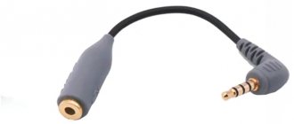
Nowadays, the pinout of headphone wires with a microphone shown in the first picture below is mostly used everywhere, but there is also another one, which is mainly used on old phones and in phones from some manufacturers. They differ in that the microphone and ground contacts are swapped.
Electret microphones
Recently, electret condenser microphones have been used in household tape recorders. Electret microphones have the widest frequency range - 30...20000 Hz.
Microphones of this type produce an electrical signal twice as large as conventional carbon ones.
The industry produces electret microphones MKE-82 and MKE-01 in size similar to carbon microphones MK-59 and the like, which can be installed in ordinary telephone handsets instead of carbon ones without any modification of the telephone set.
This type of microphone is much cheaper than conventional condenser microphones, and is therefore more accessible to radio amateurs.
The domestic industry produces a wide range of electret microphones, among them MKE-2 unidirectional for reel-to-reel tape recorders of class 1 and for integration into radio-electronic equipment - MKE-3, MKE-332 and MKE-333.
For radio amateurs, the MKE-3 condenser electret microphone, which has a microminiature design, is of greatest interest.
The microphone is used as a built-in device in domestic tape recorders, radios and tape recorders, such as Sigma-VEF-260, Tom-303, Romantic-306, etc.
The MKE-3 microphone is manufactured in a plastic case with a flange for mounting on the front panel of the radio device from the inside. The microphone is omnidirectional and has a circle pattern.
The microphone does not allow shocks or strong shaking. In table 2 shows the main technical parameters of some brands of miniature condenser electret microphones.
Table 2.
| Microphone type | MKE-3 | MKE-332 | MKE-333 | MKE-84 |
| Nominal operating frequency range, Hz | 50…16000 | 50… 15000 | 50… 15000 | 300…3400 |
| Free field sensitivity at a frequency of 1000 Hz, µV/Pa | no more than 3 | at least 3 | at least 3 | A - 6...12 V - 10...20 |
| Uneven frequency response of sensitivity in the range 50… 16000 Hz, dB, not less | 10 | — | — | — |
| Total electrical resistance module at 1000 Hz, Ohm, no more | 250 | 600 ±120 | 600 ± 120 | — |
| Equivalent sound pressure level due to the microphone’s own noise, dB, no more | 25 | — | — | — |
| Average difference in sensitivity levels “front - rear”, dB | — | no, less than 12 | no more than 3 | — |
| Operating conditions: temperature, C relative air humidity, no more | 5…30 85% at 20″С | -10…+50 95±3% at 25″С | 10…+5095±3%at 25″С | 0…+4593%at 25″С |
| Supply voltage, V | — | 1,5…9 | 1,5…9 | 1,3…4,5 |
| Weight, g | 8 | 1 | 1 | 8 |
| Overall dimensions (diameter x length), mm | 14×22 | 10.5 x 6.5 | 10.5 x 6.5 | 22,4×9,7 |
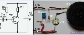
In Fig. Figure 5 shows the connection diagram for the MKE-3 type electret microphone, which is common in amateur radio designs.
Rice. 5. Schematic diagram of connecting a microphone of the MKE-3 type at the input of a transistor ultrasonic sounder.
Rice. 6. Photo and internal circuit diagram of the MKE-3 microphone, location of colored conductors.
Device and parameters
The microphone is made from:
- Electret capsule.
- Jack 3.5 plugs for connecting to a computer.
- Housing that protects the wires.
- Clamps for fixing and connecting parts.
- Thin wire 1-1.5 m long.
- Power supply.
Microphones are characterized by the following parameters:
- Sensitivity.
- Frequency range
- The difference between the highest and lowest frequency.
- The magnitude of electrical resistance.
- Characteristics of directionality.
Microphone amplifier ready circuit
But I was constantly undermined by the fact that almost all the op-amps I have are dual ones, and I don’t like it when half of the op-amp is hanging in the air. Somehow this is not kosher...
Therefore, without thinking twice, I moved on to my favorite circuit - a headphone amplifier circuit. It is essentially the same non-inverting amplifier, but supplemented with a cleverly included repeater.
The reason for the transition is not only the desire to use both operational amplifiers in the chip package.
- Firstly, I have long wanted to try this scheme with unipolar power supply.
- Secondly, this circuit is capable of delivering twice the current at the same output voltage. This ensures that there are no signal drops or distortions on the way from the preamplifier to the recording device. The cable can be 5 or 10 meters.
Therefore, all that remained was to simply add an input circuit with a microphone to it and change the values of the capacitors to suit our task. This is what the final diagram ultimately looks like.
How to find out if the connector is faulty
Insert working headphones into the jack and turn on the music. If music does not play in working headphones, your connector is broken. Also, if you hear a hissing sound when the plug moves, this means that the connector will soon completely fail.
Nowadays, the pinout of headphone wires with a microphone shown in the first picture below is mostly used everywhere, but there is also another one, which is mainly used on old phones and in phones from some manufacturers. They differ in that the microphone and ground contacts are swapped.
A simple DIY electret microphone amplifier
This microphone preamplifier may be needed if you are not satisfied with the volume level of your microphone when recording sound on a computer.
Often, in order to enhance the sound from a microphone lavalier, software amplification is done in some sound recording program or video editor, but at the same time the sound itself becomes noisy and distorted.
To avoid this, you need to amplify the sound with a preamplifier, to do this, let's solder an amplifier for an electret microphone with your own hands, this is done very simply.
What parts do we need for a microphone amplifier:
- Transistor BC547 or KT3102;
- Two resistors - 1 kOhm;
- One resistor from 150 Ohm to 1 kOhm, selected later by ear;
- Ceramic capacitor from 100 to 300 pF;
- Electrolytic capacitor 47 uF (from 6.3 V and above, but preferably no more than 25 V);
- Electret microphone (lapel microphone).
A simple DIY electret microphone amplifier
How to make an amplifier for a microphone, instructions:
Here is a diagram of a microphone preamplifier, according to which we will solder further.
A simple DIY electret microphone amplifier
This microphone preamplifier is simple, assembled with just one transistor and with a small wiring around it and does not require separate power, since it is designed to work in conjunction with a computer or smartphone. They supply a small voltage that will be sufficient for this microphone amplifier.
A simple DIY electret microphone amplifier
The entire amplifier is assembled on a small piece of a breadboard, which is included in the break of the lavalier microphone wire, which makes it almost invisible if hidden in black heat-shrink tubing. The tracks at the bottom of the board are the terminals of the radio elements themselves, bent and soldered together according to the circuit.
A simple DIY electret microphone amplifier
A simple DIY electret microphone amplifier
A simple DIY electret microphone amplifier
I didn’t immediately solder in resistor R3, first I tried without it, the sound turned out to be very loud and various unnecessary sounds and noises were getting into the microphone, so I started soldering resistors 1 kOhm, 680 Ohm, 330 Ohm and 150 Ohm one by one, listening each time on a smartphone, the most satisfactory sound for me was with a 150 Ohm resistor, which I left.
A simple DIY electret microphone amplifier
A simple DIY electret microphone amplifier
All you have to do is hide the scarf in a heat-shrink tube and your homemade microphone amplifier is ready!
How to do without a soldering iron when repairing headphones
It often happens that a person does not have a soldering iron or socket at hand, and the headphone plug does not work. In this case, we can resolder the plug in several non-standard, but acceptable ways.
The first method is to use conductive glue to glue the wires to the mini jack pins. Everything is done simply and neatly. The reliability of such fastening is of course poor, and the electrical resistance of the glue can be tenths of an ohm. If the headphone impedance is 4 -16 ohms, the glue may affect the sound volume. The good thing is that the drying time for conductive glue is usually 10-15 minutes.
The second method is to heat a nail or piece of copper wire in a candle flame. This is a way for romantics : twilight, candles, plug, headphones and you. In this case, it is better to use scented candles. But seriously, you can solder a headphone plug using a fire and coals. The main thing is not to forget good solder and flux.
The third way is to make a gas soldering iron from a lighter with your own hands. You need to take a piece of single-core copper wire and attach it to the lighter so that part of the wire is in the flame. Heat is transferred over a certain distance through a copper wire, as can be seen from the photo.
If you use this method, pay special attention to the place where the wire adheres to the lighter body. A hole may form there due to heating. Be careful! For more details on how to make such a mini soldering iron from a lighter, watch the video.
Carbon microphones
Despite the fact that carbon microphones are gradually being replaced by other types of microphones, due to their simplicity of design and fairly high sensitivity, they still find their place in various communication devices.
The most common are carbon microphones, the so-called telephone capsules, in particular, MK-10, MK-16, MK-59, etc.
The simplest circuit for connecting a carbon microphone is shown in Fig. 7. In this circuit, the transformer must be a step-up one, and for a carbon microphone with a resistance of R = 300...400 Ohms, it can be wound on an W-shaped iron core with a cross-section of 1...1.5 cm2.
The primary winding (I) contains 200 turns of PEV-1 wire with a diameter of 0.2 mm, and the secondary winding (II) contains 400 turns of PEV-1 with a diameter of 0.08...0.1 mm.
Carbon microphones, depending on their dynamic resistance, are divided into 3 groups:
- low-impedance (about 50 Ohm) with a supply current of up to 80 mA;
- medium-resistance (70...150 Ohm) with a supply current of no more than 50 mA;
- high-resistance (150...300 Ohm) with a supply current of no more than 25 mA.
It follows that in the carbon microphone circuit it is necessary to set the current corresponding to the type of microphone. Otherwise, at high current, the carbon powder will begin to sinter and the microphone will deteriorate.
In this case, nonlinear distortions appear. At very low currents the sensitivity of the microphone decreases sharply. Carbon capsules can also operate at reduced power supply current, in particular in tube and transistor amplifiers.
The decrease in sensitivity with reduced microphone power is compensated by simply increasing the gain of the audio amplifier.
In this case, the frequency response is improved, the noise level is significantly reduced, and the stability and reliability of operation is increased.
Rice. 7. Schematic diagram of connecting a carbon microphone using a transformer.
An option for connecting a carbon microphone to a transistor amplifier stage is shown in Fig. 8.
An option for connecting a carbon microphone in combination with a transistor at the input of a tube audio amplifier according to the diagram in Fig. 9 allows for high voltage gain.
Rice. 8. Schematic diagram of connecting a carbon microphone at the input of a transistor ultrasonic sounder.
Rice. 9. Schematic diagram of connecting a carbon microphone at the input of a hybrid ultrasonic sounder assembled on a transistor and an electron tube.
Literature: V.M. Pestrikov - Encyclopedia of radio amateurs.
It's been in my head for a long time. Having gathered my strength, I began to search for amplifier circuits. Most of the schemes I looked at I didn't like. I wanted to assemble it easier, better and smaller (for a laptop, because the built-in one was apparently made just for show - the quality is poor). And after a short search, a microphone signal amplifier circuit with phantom power was found and tested. Phantom power (this is when power and information transmission are carried out over one wire) is a huge advantage of this circuit, because it saves us from third-party power sources and the problems associated with them. For example: if we power the amplifier from a simple battery, it will sooner or later run out, which will lead to the circuit not working at the moment; if we power it from a battery, then sooner or later it will have to be charged, which will also lead to some difficulties and unnecessary movements; If we power it from a power supply, then there are two disadvantages that, in my opinion, rule out the option of using it - these are wires (for powering our PA) and interference. You can get rid of interference in many ways (install a stabilizer, all sorts of filters, etc.), but getting rid of wires is not so easy (you can, however, transfer energy at a distance, but why fence off a whole complex of devices to power some a microphone amplifier?) In addition, this reduces the practicality of the device. Let's move on to the diagram:
When you might need it
The most common use of phantom power is when connecting condenser microphones. This is due to the principle of operation of such a microphone, which repeats the principle of operation of a capacitor. One of the capacitor plates is stationary, and the role of the second, movable one, is played by the microphone membrane, which moves more or less depending on the source of the acoustic signal. If the capacitor has a charge, then, as we know from the school physics course, we change the capacitance of the capacitor when the movable membrane is displaced.
A change in capacitance leads to a change in voltage, which is the signal from the microphone. But for such a circuit to work, a polarizing voltage is needed between the plates. For some time now, such microphones have been supplied with a voltage of 48 V, which is today accepted as the standard phantom power voltage. A variation of the condenser microphone is the electret microphone. It usually has a small battery and requires less than 48V phantom power.
Phantom power is supplied to the microphone through the microphone cable. But where does it come from? Phantom power supplies can be built into mixing consoles with the ability to be supplied separately to each channel with microphone preamplifier or to a group of channels; Often this power is supplied immediately to all channels where a microphone can be connected, which reduces the final cost of the mixer.
Another source of phantom power can be a microphone preamplifier. Typically, this option is provided on all microphone preamps. Finally, separate phantom power supplies are produced that do not have any additional capabilities other than supplying the phantom. It should be noted that phantom power voltage also powers the internal circuitry of condenser microphones. Without phantom power, condenser microphones simply won't work.
How does microphone phantom power work?
Low output impedance
Resistors R1 and R2 provide the appropriate output impedance and power from a 10V source. The basic performance of this simple capsule is excellent, but it requires further signal processing to meet professional microphone phantom power standards. The output of a microphone with phantom power is a low-impedance differential signal. The low output impedance is provided by a simple buffer on IC1. The unity gain inverter on IC2 receives power from the output of IC1.
The bias for the non-inverting input of IC2 is the well-filtered output voltage of IC1. The IC1/IC2 dual amplifier was chosen for its low noise and low distortion properties. R6 and R7 are designed to protect against long line capacitance, RFI, and voltage surges that occur when hot plugging into a phantom power supply.
To prevent direct phantom power voltage from reaching the audio signal lines, separating capacitors C2 and C3 are included at the amplifier outputs. The output differential voltage swing is limited to approximately 2 Vpp due to the inability of the power supply to support the op amp output currents at higher voltages. However, this level is sufficient because it corresponds to the linear range limits of the capsule.
What is impedance.
48V phantom power supply
Phantom powered microphones receive power for their active circuits from the receiving end of the circuit through the same wires that carry the audio signal. The 48 V phantom power supply is connected to both signal lines through 6.8 kOhm resistors R10 and R11. This connection allows a microphone with a low output impedance to transmit a differential AC signal with a relatively “soft” impedance characteristic of the phantom power supply. Power is supplied to the microphone from the signal lines through resistors R8 and R9. Zener diode D1 regulates the power supply to the microphone and amplifier.
In addition, these resistors provide a soft impedance characteristic of a symmetrical line. You can place a microphone hundreds of feet from the phantom power supply and receive-side amplifier and still get excellent performance. The receive side uses a low-noise instrumentation amplifier IC3, consisting of three internal operational amplifiers. Its configuration and laser trimmed resistor values provide excellent common mode rejection ratio (CMR).
48V phantom power supply power circuit.
Noise and background suppression
High CMR suppresses power bus noise and hum that have equal amplitudes on both signal lines. While low noise (1nV/√Hz) is not needed for high-output microphones like the one described here, it is necessary for professional ribbon and electrodynamic microphones with low output signals. These types of microphones are strictly passive electromechanical generators and do not require a power source.
Microphone phantom power gets its name because these types of microphones are driven at 48V. Electret capsules are available in a variety of sizes and physical configurations. In particular, they can be either omnidirectional or directional (with a cardioid polar pattern). Directional capsules have a vent at the back; To achieve proper performance, they should be installed to allow easy access from both the front and rear.
Microphone preamplifier with 2 transistors
The structure of any preamplifier greatly affects its noise characteristics.
If we take into account the fact that the high-quality radio components used in the preamplifier circuit still lead to distortion (noise) to one degree or another, then it is obvious that the only way to get a more or less high-quality microphone amplifier is to reduce the number of radio components in the circuit. An example is the following circuit of a two-stage transistor pre-amplifier
With this option, the number of decoupling capacitors is minimized, since the transistors are connected in a circuit with a common emitter. There is also a direct connection between the cascades. To stabilize the operating mode of the circuit when the external temperature and supply voltage change, a direct current feedback loop has been added to the circuit.
Criterias of choice
It is important to consider all characteristics before purchasing. The main criteria are:
The main criteria are:
- Sound. Each microphone has its own preamplifier. In the middle and low price segments, it often happens that with a given acoustic device, a transistor preamp gives a more favorable effect than a tube one.
- Gain range. It must be sufficient to solve the assigned tasks.
- Overload reserve, i.e. the maximum permissible voltage of the signal arriving at the input. Depends on microphone sensitivity and the highest possible sound source strength (SPL).
- Noise. Together with a similar microphone parameter, it should not exceed the specified value. The lowest noise microphone is a dynamic microphone.
- Signal to noise ratio. The higher this parameter, the higher the quality of the audio stream.
Number of inputs
If you need to connect several microphones, select a converter with the appropriate number of connectors. It is recommended to purchase a model with 2 or more inputs, even if the sound source is currently 1. In the future, the situation may change, and then you will not have to buy a new preamp.
Built-in limiter
The limiter compressor is activated during overloads to avoid distortion of the audio stream. It performs 2 functions:
- limits the signal level;
- compresses dynamic range.
In most cases, this component can be dispensed with. But if 2 models cost approximately the same, it is better to choose one with a limiter.
Low pass filter
This component rejects signals with frequencies below 200 Hz. As a result, interference is suppressed, for example:
- hum from instruments;
- nasality;
- barreliness.
Level indicators
The quality of the recording depends on how close the signal level is to the optimal level. This term refers to the maximum possible value at which noise remains acceptably low. Therefore, level indicators or at least overload indicators are an important component of the preamp. Without them, the sound engineer works blindly.
There are 2 types of indicators:
- switches;
- LED
The latter are easier to take readings, but they display the signal level discretely.
Phase switch
Another name is the phase reversal or phase inversion button. The need for this operation sometimes arises when recording from several microphones simultaneously.
Phantom power
The power supply must be selected in accordance with the technical specifications of the microphone.
The following statements are common:
- a voltage of 48 V provides higher sound quality compared to, for example, 12 V;
- By increasing the voltage you can expand the dynamic range of the pickup.
This is only true for a small portion of microphones. Most of them work well in the range of 12-48 V or 9-52 V, the increase in voltage does not affect the acoustic device capsule and its electronic circuit. This is because phantom power does not supply the microphone directly, but through an internal, regulated source.
Those who have difficulty selecting parameters for this component are advised to consult the cartridge manufacturer.
Low-noise microphone ULF using transistors
Figure 2 shows an example of a ULF circuit using transistors. In the first stages, the transistors operate in microcurrent mode, which minimizes internal ULF noise. Here it is advisable to use transistors with a high gain but low reverse current.
This could be, for example, 159NT1V (Ik0=20nA) or KT3102 (Ik0=50nA), or similar.
Rice. 2. ULF circuit on transistors and options for connecting microphones: a ULF on transistors, b - connection of a dynamic microphone, c - connection of an electret microphone, d - connection of a remote microphone.
Elements for the circuit in Figure 2:
- R1=43k-51k, R2=510k (adjustment, Ukt2=1.2V-1.8V),
- R3=5.6k-6.8k (volume control), R4=3k, R5=750,
- R6=150k, R7=150k, R8=33k; R9=820-1.2k, R10=200-330,
- R11=100k (adjustment, Uet5=Uet6=1.5V),
- R12=1 k (adjustment of the quiescent current T5 and T6, 1-2 mA);
- C1=10uF-50uF, C2=0.15uF-1uF, C3=1800,
- C4=10µF-20µF, C5=1µF, C6=10µF-50µF, C7=100µF-500µF;
- T1, T2, T3 -159NT1 V, KT3102E or similar,
- T4, T5 - KT315 or similar, but MP38A is also possible,
- T6 - KT361 or similar, but MP42B is also possible;
- M - MD64, MD200 (b), IEC-3 or similar (c),
- T - TM-2A.
The use of such transistors allows not only to ensure stable operation of the transistors at low collector currents, but also to achieve good amplification characteristics with a low noise level.
Output transistors can be used either silicon (KT315 and KT361, KT3102 and KT3107, etc.) or germanium (MP38A and MP42B, etc.). Setting up the circuit comes down to setting resistor R2 and resistor RЗ the corresponding voltages on the transistors: 1.5V on the collector T2 and 1.5V on the emitters T5 and T6.
About the colors of wires in headphones
Headphone wire colors are usually standardized. The wire colors for standard headphones with 3 wire types are shown in the photo below.
However, there are still manufacturers who use non-standard wires for soldering headphones and marking channels. For example, Apple uses two-color wire markings in its AirPods headphones.
In such cases, the Internet or the method of checking with a 3-volt battery or multimeter comes to the rescue.
When voltage is applied (with a battery or a multimeter in ohmmeter mode) between the contacts of the speaker, a rustling sound will be heard in it. It's simple. It’s more difficult with headsets, especially if they have buttons. This is where circuitry comes into play. Because manufacturers often use a minimum of pairs of wires to transmit a large number of signals.
Operating principle of an electret microphone
The device is made of parts consisting of a hard part and a soft film. Electrons enter it, but cannot pass through freely. Because of this, an electric charge is formed around the material, which persists for quite a long time. The top of the film is specially coated with steel, which acts as an electrode. And next to it is an iron cylinder, with its flat side facing the ring.
The membrane transmits acoustic waves, after which a current is created. The strength of the generated current is too small, and the resistance for it is high. This makes it difficult to transmit the audio signal. To coordinate all the parameters of the device and make it work, a special cascade is installed. It consists of unipolar transistors. The microphone's operation relies on the ability of certain materials to adjust electrical charge.
To check whether it is possible to combine devices, it is enough to compare the values obtained using a multimeter. If after measurements the value is 2-3 W, then they will be able to work together.
Does microphone type depend on sound level?
The signal that a microphone produces depends on its type.
Different types of devices have different sensitivities. This is the ratio of the voltage at the output contacts of the device to the force on the sensitive element (diaphragm, dielectric). Condenser microphones have the highest sensitivity. They have an intense output signal and good reproduction of sound shades. Because of these characteristics, the devices are used in professional sound recording.
The lowest indicator is for electret devices. Although they are close in design to capacitors, they have a low output signal level. Electret microphones are often built into computer headsets, smartphones, and other compact devices.
Connection rules
Since electret microphones have a fairly high output impedance, they can be connected to receivers and amplifiers with high input impedance without any problems. To check the amplifier's performance, you just need to connect a multimeter to it, and then look at the resulting value. If, as a result of all measurements, the operating parameter of the equipment corresponds to 2-3 units, then the amplifier can safely be used with electret equipment. The design of almost all models of electret microphones usually includes a preamplifier, which is called an “impedance converter” or “impedance matcher.” It is connected to an imported transceiver and mini-radio tubes having an input impedance of about 1 ohm with a significant output impedance.
In general, the connection diagram looks like this.
To maintain proper operation of the device, it is important to supply power to it with correct polarity. For a three-input device, the minus connection to the housing is typical; in this case, power is supplied through the positive input
Then through a separating capacitor, from where a parallel connection is made to the input of the power amplifier.
The two-output model is powered through a limiting resistor, also to the positive input. The output signal is also removed here. Further, the principle is the same - the signal goes to the isolation capacitor, and then to the power amplifier.
How to connect an electret microphone, see below.
Source
How to properly connect an amplifier in a car
There are three main problems related to the layout of automotive audio equipment. This is the wrong choice of connecting wires, their illiterate laying and poor-quality grounding, or rather the connection of equipment to the car body. Connecting the amplifier to the car must be done with wires of the appropriate cross-section. Any metal wire has a certain resistance. The thinner the wire, the higher its resistance, so you cannot install it with SHVVP wire, which is widely used in everyday life. Many companies produce copper-plated wire containing steel conductors coated with a thin layer of sputtered copper. It is unacceptable to use such wires to connect a car amplifier. This will not only greatly reduce the sound quality, but may also cause a fire. To work, you need to purchase special cables designed for such installation.
To understand how to connect an audio amplifier in a car
, you need to calculate the current in the circuit. To do this, you need to divide the amplifier power by the supply voltage. Since the device is powered by a car battery, the total power of the channels must be divided by 12 volts. A two-channel device with a power of 60 watts per channel has a total power of 120 watts. It is customary to increase the power by 1.5-2 times due to uneven consumption, so in this case a power of 240 watts is considered. 240 watts/12 volts = 20 amps. Based on this value, the wire cross-section is selected. The power of a four-channel system with a subwoofer reaches 800 watts or more, so all connecting cables must have the appropriate cross-section. The thin wire will heat up, which may cause a fire. When choosing a cable, it should be chosen with a reserve in terms of power and length. It is not recommended to wire the wires under tension. To reduce distortion, you often have to look for the correct position of the wires relative to each other. The diagram for connecting speakers through an amplifier in a car does not allow parallel laying of power cables and wires going to the speakers. This leads to interference in acoustic systems.
Reasons why you can't connect a preamp to your receiver
As we mentioned in this article, not every AV receiver has an HT Bypass or Direct In input. For the most part, only high-quality AV receivers do this.
It is important that you do not try to connect a preamp to a normal input because this will cause the AV receiver's preamp to operate at more voltage than it is designed for. If you need to use a preamp but your AV receiver won't let you bypass it, that doesn't necessarily mean you should upgrade to a more expensive AV receiver
Instead, you can connect your preamp to the device it was designed for - a power amplifier
If you need to use a preamp but your AV receiver won't let you bypass it, that doesn't necessarily mean you should upgrade to a more expensive AV receiver. Instead, you can connect your preamp to the device it was designed for - a power amplifier.
A power amplifier is basically what you turn your AV receiver into when you use the HT Bypass or Direct In inputs, so if you're looking to upgrade to accommodate a preamp, purchasing a power amplifier may be a more cost-effective option. go.
Recording source: https://thehometheaterdiy.com
Parallel connection diagram
When connected in parallel, the load resistance drops and the output power increases in proportion to the number of speakers
Here you should pay attention to the maximum permissible load on the amplifier and the number of channels
Most models are designed for a load of 2 ohms, less often 1 ohm, but for high-quality sound and longevity of the equipment, it is advisable to create an optimal load for the device. So, for example, when connecting two speakers with R = 4 Ohms and two speakers with R = 8 Ohms to an amplifier with R = 8 Ohms, we get the permissible resistance of all speakers (4+4+8+8=24 - total; 24: 4=6 - total resistance per device).
- The negative channel of speaker 1 and speaker 2 is connected to the positive terminal of the device.
- Positive - to the negative contact of the same channel.
- All others are connected according to the same principle.
Marking
The microphone brand is usually marked on its body and consists of letters and numbers. The letters indicate the microphone type:
- MD - reel-to-reel (or "dynamic")
- MDM - dynamic small-sized,
- MM - miniature electrodynamic,
- ML - tape,
- MK - capacitor,
- FEM - electret,
- MPE - piezoelectric.
The numbers indicate the serial number of the development. After the numbers there are letters A, T and B, indicating that the microphone is made in an export version - A, T - tropical, and B - intended for household radio-electronic equipment (REA).
The marking of the MM-5 microphone reflects its design features and consists of six symbols:
- first and second……………MM - miniature microphone;
- third ………………………….. 5 – fifth design;
- fourth and fifth ……….. two digits indicating the standard size;
- sixth …………………………. a letter that characterizes the shape of the acoustic input (O - round hole, C - pipe, B - combined).
In the practice of radio amateurs, several main types of microphones are used: carbon, electrodynamic, electromagnetic, condenser, electret and piezoelectric.