I hope that some of my fellow citizens may be interested in such an archaic instrument as a pre-amplifier-corrector
for vinyl with standard RIAA rating.
At work in the theater, I urgently needed to send a signal from a vinyl record player to the linear input of the computer's sound card, for which I needed an appropriate corrector amplifier.
We have seen all the power tool pickups here. Let us recall, in passing, that none of these devices speak of a microphone, that is, a sensor of wave-like changes in air pressure at a given point. The Daily Miracle converts mechanical movement into electricity and then makes this movement of current in a set of circuits that change that current to end up reconnecting it to another device that converts in a different direction the current in mechanical movement that can move air masses into our eardrums. seems so commonplace that we forget the complexity of the phenomena that comes into play.
A fragment of a board of an unidentified “AKAI” model was taken, on which there was an intact section with a similar corrector (hereinafter referred to as the CC), assembled on a C4558
. When power was applied to check the operation of the UC, and a player and a control amplifier were connected to the sockets, the UD began to work with noticeable noise and nonlinear distortion.
Let's combine our sensors, our vibration devices, our circuits and our wiring, and with it all a little emotion! Sometimes it can be interesting to place two microphones in different positions, calculating that the tilt, especially the microphone located in front of the hole, will be lower if placed above the sixth string or higher if placed under the first rope. The most correct position is also based on the type of guitar you are using, as each instrument prefers a certain frequency range in the sound spectrum, and so it can be helpful to try different angles to get the best sound out of the instrument.
In my opinion, the cause of the noise and distortion was the electrolytic capacitors at the input of the device and in the feedback circuit. When they were closed with jumpers, the noise and distortion disappeared, but the control unit became sensitive to various kinds of external interference. Almost all the parts used were from the “original material”, except for the electrolytes. They were purchased specially. In terms of power supply, they are so “capacious” (6800mF) that they can do without an extra voltage stabilizer. In addition, I believe that all the extra “additives” in the power circuits introduce their own, sometimes not the most desirable, adjustments (for example, thermal noise).
One last tip: microphone distance is very important as it can affect the return of sounds from other instruments. If the mic stays far away to get the right volume, you need to increase the relative control, in which case any other sounds picked up from the mic itself will also occur. Conversely, micing too close may not increase the age of the instrument. So try different positions and see what works best for both cleaning and sound effect, creating a good compromise. Finally, it can be said that many problems come to life as there are various environmental factors in the recording room that will improve the clarity and sound quality of the microphone.
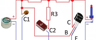
Scheme
Electrolytic capacitors at the input and in the OOS circuits were excluded from the original circuit (previously they were connected in series with resistors R3, R4, R5 and R6).
At the output of the device, analogs of non-polar electrolytic capacitors with a bias voltage were included (C5, C7, R13 and C6, C8, R14). The connection circuit for the ground bus has been changed, which now consists of two “stars” separated by resistor R19. The power supply at both poles is organized according to the same “star” scheme, which ensures high resistance to external interference.
An acoustic guitar can be fitted with a magnetic pickup of the type used for electric guitars. This signal responds to the vibration of the rope, but has minimal effect on the harmonic body and is therefore unusable since the sound The result will be an intermediate between the natural sound of the instrument and the electric sound of the pickup truck. This system will lose many of the acoustic qualities of an acoustic guitar. If only recommended if you want to spend very little without interfering with the violin on the guitar. tool.
Currently, the best way to amplify an acoustic guitar without using a microphone is with a piezoelectric transducer. There are different models and different application possibilities for this type of pickup truck. The most classic of these consists of a small block of crystalline or ceramic material. encapsulated in a metal or plastic case, on the surface of which two output wires are welded. This device is attached to the dashboard and works on the principle of the piezoelectric effect.
DA1 – C4558 R1, R2 – 47k R3, R4 – 1.8k R5, R6 – 2.2k R7, R8 – 390k R9, R10 – 33k R11, R12 – 180 R13, R14 – 330k R15, R16, R17, R18 – 100k R19 – 100 C1, C2 – 8200pF C3, C4 – 2200pF C5, C6, C7, C8 – 2.2mF * 50v -Toshiba C9, C10 – 6800mF * 25v – Toshiba C11, C12, C13, C14 – 0.1mF VD1 – KTs405A
Main difficulties
Players from “reputable” and well-known companies, as a rule, do not contain any pre-amplifiers, at least I come across just such ones. They simply have direct output from the pickup. Some explain this by saying that all preliminary amplification stages should be located as far as possible from sources of strong interference and interference, such as, for example, electric motors and transformers. Good turntables often use small, low-voltage DC motors with a power supply in the form of a remote “adapter.”
This apparently makes sense. In any case, the preamplifier-corrector must be placed in a shielding metal case connected to the “Common” wire of the circuit (!) and it is also advisable to take the power supply for it outside (make it in the form of an “adapter”), or also carefully shield it.
Assembly and configuration
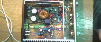
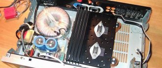
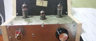
The entire device was assembled on a breadboard and placed in a tin case, which was then squeezed into two identical plastic boxes, one of which was equipped with a block with RCA type sockets.
A power transformer - any low-power one with a voltage on the secondary winding of about 18-25 Volts (and preferably with a separating screen winding) was placed in the housing of the power supply - “plugs” along with a rectifier bridge, which could be, for example, KTs405A.
It is excited by the vibrations that travel through the wood of the guitar table when the strings are in vibration, in practice, when he plays. These excitations allow electron leakage to the side of the transducer adjacent to the table, making all charges on that side negative when the vibrating table moves outward. When the latter moves inward, electrons migrate towards the opposite surface, by changing polarity. These changes will be transmitted as alternating current through two output cables.
The power supply is connected via a three-wire cable (this can be a balanced microphone cable) using a suitable three-pin connector, which can be XLR or “DIN”, an analogue of the Soviet “SG-3”.
After proper assembly, the device begins to work immediately.
Because The direct current feedback is not one hundred percent, then a constant voltage of about +1 Volt has formed at both outputs of the microcircuit, which is not a problem.
In some cases, the signal may be so weak as to force the preamplifier to force the signal itself to amplify. A piezoelectric pre is very different from a regular electric preamp as it is a small circuit that sometimes accepts an equalizer and can also be inserted inside the instrument. This system reproduces the acoustic timbre of the instrument with excellent accuracy.
Many acoustic guitarists choose to amplify their instrument using piezoelectric transducers and the use of microphones, mixing different sounds through a mixer and getting the best sound. In any case, the problem to keep under control is feedback. This effect, so expensive on many electric guitars, is a nightmare on acoustic ones. To overcome this, you must first keep the tool away from your drawers and never in front of them. since "whoosh" tends to develop at certain frequencies, while typical resonance prefers low frequencies.
The whole structure turned out to be unsightly - it was necessary to solve the problem urgently, within a day. However, it has been working safely for almost eight years now. Whoever repeats can have a hand in the appearance, I wish you success. Laboratory measurements of device parameters were not performed.
PS
I did not disassemble the entire structure to photograph the board with parts, because... she is “on the go.” Every day my father listens to his favorite vinyls. When developing a “signet”, you should proceed from the dimensions of the parts, cat. may differ from those I used.
Next, you should check for reduced rates in the reverb, as they can create very annoying resonances. As always, you should try out the position of the mics during soundcheck so you don't have any last minute surprises during your run-through.
On the market today we have amp models built for use with acoustic guitars. Their circuitry is tailored to the specific frequency of the piezoelectric, these are pre-amplified or not, and in many cases also come with built-in effects such as reverb and chorus, and send effects, for connecting an external modulation, delay and reverb unit. The sound quality varies from amplifier to another, but the more demanding ones prefer without a doubt MIX or connection directly from the mixing console, thus feeling their own sound in the light.
Addition from MVV:
If I were to replicate the design, I would do the following: 1. Install a low noise op amp, such as the OPA2134 or OPA2604. 2. I replaced the non-polar capacitors at the output (C5, C7 and C6, C8, respectively) with MKTs with a capacity of 1...2 µF for an operating voltage of 63 or 100 V. 3. Slightly changed the correction circuit of each channel (the figure shows the circuit of the left channel):
Proper ground handling is of great importance, especially in audio and digital circuits. For example, the mass of an LED, such as in an audio amplifier, results in an increase in the mains audio that can be heard in a loudspeaker. This also increases the level of other interruptions and the electronic system may become unstable.
Designing a mass correctly requires certain rules and a lot of practice. The most important rule is that we do not create masses. This means that the mass should not form a closed loop in which current flows. Sometimes the weight belt is created in places we don't think about when designing.
Here R3=180 Ohm, R7=120 kOhm, R9=12 kOhm, Radd=1.1 kOhm, Add=47 µFx25 V, non-polar, C1=0.027 µF, C3=6200 pF. The gain will be Ku=74(37.4 dB). RIAA time constants - corrections correspond to GOST 7893-73: T1=R9C3 (75 µs), T2=R9C1 (318 µs), T3=R7C1 (3180 µs). In addition, for correction according to the RIAA-78 standard, the T4=R3Cadd circuit (7950 μs) was introduced. As a result, the DC gain will become equal to unity, which will reduce the zero offset voltage at the output to a few millivolts.
Preamplifier corrector for vinyl on ultra-low noise chips
I wanted to make a preamplifier for vinyl, which would certainly provide the highest parameters and guaranteed high-quality sound. To make it possible for those interested to repeat it, I have provided modes of operation of the cascades that would be installed automatically when using a diverse element base and, if possible, would not require configuration.
During design, scales are run from individual components to a single point, or we run from input to output. It is difficult to say which method is better, depending on many factors. Often there are mixed systems, that is, the mass rails are connected at a common point.
The mass paths must be much wider than the signal paths. This principle also applies when the system is assembled using the point-to-point method using conductors - the ground wire must have a larger cross-section. For a little more about weight management, please read the page: "Electrical Nutrition".
Specifications:
- Gain at a frequency of 1 kHz for the MM head is 40 dB;
- Gain at a frequency of 1 kHz for the MS head is 60 dB;
- Input impedance for the MM head is 47 kOhm;
- Input impedance for the MS head is 200 Ohm;
- Signal to weighted noise ratio - 78 dB;
- Rated output voltage of a signal with a frequency of 1 kHz is 1.5 V;
- Total harmonic distortion is 0.00257%.
The nominal output voltage of the corrector preamplifier for vinyl was checked from a measuring plate with a GZM-003 magnetic head. The output voltage corresponding to the 0 dB level is close to the output level of the CD player. The preamplifier-corrector circuit for magnetic heads is shown in Fig. 1, and its practical implementation “in hardware” in Fig. 2 - 6.
Placement of components on the printed circuit board as well as in the device. Electronic device components can be affected by capacitance, inductance and temperature. Capacitance is a particularly high frequency. Placing a capacitor in the wrong location or near another component or even a ground wire can cause harmful interference and can sometimes interfere with the operation of the device. Also, long lead wires have some capacitance, which can impair performance in some cases.
Inductance - Inductive coupling may occur, as in the case of capacitance failure. In a tube amplifier, the main component contributing to the inductance are the transformers and the filter choke. For example, on power cables, place sensitive components in shielded copper containers. The metal grounded body of the device significantly reduces this adverse effect. The magnetic field coming from transformers or chokes is induced in the wires that are in the alternating magnetic field of the fault, which degrades the quality of the output signal.
Circuit design
In the literature I found several descriptions of switching on the low-noise operational amplifier LM833. As a sample for constructing correction circuits, I used the principles of combining passive and active links from the article. The first stage of my preamplifier for vinyl is assembled on an SSM-2019 chip, designed for building microphone amplifiers. This chip has ultra-low noise density of 0.5-1 nV/Hz and high open-loop gain. Its gain is set in the range from 1 to 1000 by changing the resistor value between 1 and 8 legs (R5 - 4.32 kOhm). By appropriately connecting the input circuits of this microcircuit, you can switch the preamplifier corrector for vinyl to differential (balanced) mode. In the diagram, this corresponds to the right position of toggle switch SA1. Differential switching is much more advantageous than conventional asymmetric switching in terms of common-mode noise suppression and background reduction.
This is especially annoying for amplifiers and other tubular devices because the power transformers and filter choke vary in power, so the magnetic field around them makes a big difference. The field induces a voltage in the loudspeakers, which can then be heard in the loudspeakers as a mains broom. This is a big problem because there are usually three transformers and possibly an inductor in the case. Transformers may be placed 90 degrees apart, the maximum distance allowed by the conditions.
In my Dual 701 turntable, there are five thin wires running through the tonearm tube: two wires from each of the two cartridge terminals and one from the tonearm tube itself. So in my case, implementing a symmetrical (balanced) connection of the pickup head to the preamplifier and corrector was not a problem. The output from the tonearm tube in a balanced connection is the “ground” and an additional shield for the wires coming from the pickup head.
You can try shielding with steel sheet, although this is quite limited due to the high permeability of the 50 Hz magnetic field. High temperatures emitting electrons are always a problem as they shorten the life of electronic components, sometimes running the system too high and damaging them very quickly.
In the case of conductors, high temperature changes the operating point, which must be taken into account when designing the system. Lamps by nature are designed to operate at high temperatures, but temperatures that are too high can significantly reduce the life of the lamps. Typical and limiting values are usually indicated in the lamp catalogue. This also has a negative impact on the longevity of the pedestal and other items nearby. Therefore, the lamps must be sufficiently cooled.
The noise characteristics of this specialized op-amp chip are very good and therefore, my vinyl corrector preamplifier works great with the MC (moving coil) cartridge head. It achieves an excellent signal-to-noise ratio without the use of difficult-to-manufacture step-up input transformers. To work with the MC head (with a moving coil), you need to short-circuit contacts S4 (and S3 in the second channel) with jumpers. The input impedance in MS mode is reduced to 200 Ohms from the standard 47 kOhms for MM mode. The gain of the first stage increases by 10 times. Typically, the input capacitance of a separate vinyl corrector preamplifier is about 100 pF, which, combined with the capacitance of the input cable and wires running in the tonearm, is about 300 pF. To correct one of the poles of the pickup head, this capacity is close to optimal. By using jumpers S1 and S2 at the input, you can increase the input capacitance in the range of 60-160 pF, which is useful when fine-tuning the preamplifier of the vinyl corrector.
Resistors - Resistors that overheat have a shorter lifespan, and some resistances change with temperature. Resistors operating in “sensitive” areas of the circuit after heating produce more noise. Conditions for thermal conductivity and power must be provided, which must correspond to the corresponding power dissipated in the resistance. Replacing the radiator with a resistor improves operating conditions and extends service life.
Electrolyte capacitors age faster, losing power as the electrolyte dries out. Let's also remember that heat from heating elements moves to the print tracks and through them to other elements. In extreme cases, this can lead to the element being soldered at hot spots.
The required frequency response of the corrector preamplifier for vinyl is formed by the passive correction circuit R7R8C3C4 and the active link on the operational amplifier DA3. An additional pole at a frequency of 21 - 22 Hz is formed by the R7R8C3 circuit with a time constant: 75 µS. The roll-off of the frequency response at low frequencies is determined by the R7R8C4 circuit (with a lower cutoff frequency at 3 dB). The time constants 3180 µS and 318 µS, standard for the pickup head, are set by the active link of the corrector preamplifier on the DA3 chip.
For example, heat from a very hot rectifier bridge will be transferred to the electrolytic capacitors of the filter, heating it to a high temperature, although, of course, this will negatively affect its durability. Soldering bad parts. Contrary to appearances, this often happens even with experienced electronics. Misplacing a single solder resistor, solder capacitor at too low a voltage, or solder it the other way around can cause malfunction or even damage to many components of the assembly system.
This will prevent us from spending unnecessarily on purchasing new products. And the basic principle: before soldering, we measure the elements, matching them in pairs, for example, with two channels of an amplifier, so that they have the same value. Damaged components - In this case, the device may fail or malfunction. If we use new elements, this is rare, but if we use elements from the gap, it is necessary to check them, at least those parameters that can be checked. Resistors are measured with an ohmmeter before soldering, since their value can differ significantly from the value set for the case.
The capacitance of capacitors C4 and C5 was chosen slightly lower than those recommended by the RIAA, as a result of which the frequency response of the preamplifier for vinyl at low frequencies differs slightly from the RIAA to the IEC recommendations. This significantly reduced the rumble of the turntable engine.
The output stage of the vinyl corrector preamplifier is built on the OP279 (DA4) operational amplifier. An operational amplifier of this type works stably for capacitive loads up to 0.01 μF or for headphones with a resistance of 32 to 600 ohms. Resistor R12 protects the output of the operational amplifier DA4 from short circuit. To reduce the background level, the preamplifier and vinyl corrector uses voltage stabilizers DA7, DA8 with an output voltage of +/- 6 V. Power supply Fig. 2 has no special features and is designed as an external adapter combined with a power plug.
Details and design
When the variation in the values of parts in the frequency-setting circuits is no more than ± 1%, the maximum deviation of the frequency response of the preamplifier for vinyl does not exceed 0.1 dB. The difference in the ratings of the frequency-setting circuits in both channels of the device should be minimal.
Resistors R4 and R12 types OMLT-0.25. All others with a tolerance of 0.25 ... 1% (precision metal oxide: S2-14 S2-ZZM, S2-29V, but not wire). Precision resistors have very noise and high temperature stability. Capacitors C1, C2 types K10-17 or imported, they do not greatly affect the sound quality.
Capacitors C3, C4, C6. It is permissible to use only film ones, and the film must be non-polar, i.e., made of propylene or polystyrene. By the way, polycarbonate capacitors of the K77 type are made on the basis of a polarized film and are not suitable here. As capacitor C4, you can use imported polypropylene (used in network noise suppression filters). Soviet K78-2 capacitors have significant dimensions and, due to the greater variation in capacitance, are more difficult to pair.
Capacitors C3 and C6 type K71-7 with a polystyrene dielectric. Foreign-made polystyrene capacitors can also be used in the preamplifier/corrector for vinyl. The value of resistor R8 should be about 50 kOhm, and resistor R7 = 3 - 10 kOhm. A decrease in resistance R7 causes an increase in nonlinear distortions of the DA1 microcircuit at high frequencies, and an increase reduces the transmission coefficient of the passive circuit and increases the influence of DA3 noise. Allowable capacitance value of capacitor C3: 0.009 - 0.0265 µF. Instead of one precise resistor of non-standard value, you can use two ordinary ones, connected in series or parallel.
The total gain of the equalizer preamp for vinyl at 1 kHz is about 40 dB when working with MM (moving magnet) heads. It is advisable to distribute the gain equally between the first and second stages. Resistor R9 should have a value of 500 - 600 Ohms. When it increases above 700 Ohms, the noise of the stage on the DA3 chip increases, and when it decreases, the load on the output stage increases.
Capacitor C5 is oxide bipolar. Such capacitors differ from non-polar ones by having lower losses at high frequencies and, in the absence of bias voltage, by much better characteristics. They are designed to work in passive filters of acoustic systems and are produced by the following companies: Elna - RBP2 series, Nichicon - ES series, etc.
The power supply uses a small-sized transformer TPG-2- with a voltage of secondary windings of 2x18 V. Any transformer with two windings with a voltage of 14 - 18 V and a current of 50 mA will be suitable for the preamplifier corrector for vinyl.
The printed circuit board and the arrangement of elements are shown in Fig. 3 and 4. Jumpers are soldered into the holes marked with a cross. The pins of the parts marked with a cross are also soldered on both sides of the board. The design of the corrector preamplifier for vinyl is shown in the photo.
In Fig. Figure 5 shows the distortion spectrum of the device, measurements were carried out using the Spectra Lab program on a computer with a 24-bit PCMCIA audio card Indigo io ECHO. To increase accuracy during measurements, the laptop was powered by a battery with the mains power supply turned off.