Installing a speaker in a car in some cases is the only way to improve the sound quality of the speaker system in a car. The devices provide harmony and natural sound. To significantly improve the sound and make listening to music comfortable while driving, you need to choose not only the right horn speaker, but also connect it to the radio in your car.
What are tweeters and why are they needed?
To achieve the best effect, tweeter acoustics are installed together with a subwoofer, i.e. amplifier that reproduces low frequencies. It is not advisable to use such speakers separately from others. They are part of the acoustics system. Thus, horns are needed not as the main source of sound, but as auxiliary elements necessary to improve the quality of reproduction.
About capacitors vol.3
Don't want to watch ads? Register!
A few words about the basic parameters of a capacitor that determine its effect on the signal.
Read - FOR YOUR SOUND!
Having studied the previous article in detail, I found that not a single word was said about the device and parameters of the capacitor. But many of us have either already forgotten the school physics course, or skipped it, or are so inquisitive that it hasn’t started yet according to the school curriculum ((or maybe it won’t start - I don’t know what’s happening there now, in this school).
Get to the point! And so, dear reader, first I suggest you find a capacitor. Found? Now pick it apart, buddy. What do you see?
There are not many options: 1) Ceramic capacitor - you will see 2 metal plates with a tiny layer of this same ceramic (that is, almost clay, of a special composition). It was covered with a protective layer on top. Ceramic capacitors are inexpensive and practical. Sound? And it’s like with felt-tip pens - each one has a different taste and color. (Read previous article)
2) Film capacitor - here, most likely, you will see foil with a layer of film. This type of capacitor is the most common in guitars. And not only guitars. There are many types of film capacitors - different compositions and shapes. They are also covered with a protective layer on top. This type of capacitors is more expensive than ceramic ones. How much? Depends on the composition (i.e. materials) and parameters of the capacitor. It can be from 2 to 100 times more expensive.
3) Paper-oil capacitor. Congratulations, you've taken apart the most iconic of all capacitors! :)) These capacitors represent a special type of film capacitors. They use foil as coverings, and the dielectric is paper impregnated with oil. They have the main disadvantage - aging. Because the oil evaporates and the paper (i.e., dielectric) changes its properties. These capacitors are also used in the production of tube amplifiers (previously - for lack of others, now - due to their cult status, trying to make them look vintage).
Let's return to film capacitors in general! — in them, oil-impregnated paper is replaced with a film made of polymers and various other materials. They do not have the disadvantages of paper ones; top models are used in the production of Hi-end equipment.
Yes! And you most likely paid attention to the inscriptions that were on the capacitor. For example: .022 50V This is how the manufacturer shows the parameters of their products. The first is capacity. The second is maximum voltage.
Capacitance is a parameter that affects the cutoff frequency. The larger the capacitance, the lower the cutoff frequency. Those. roughly speaking, the larger this value, the less high frequencies there will be in the output signal (if the tone is turned on).
Here is a table of capacitor capacities and their designations:
Still have questions?
Why is it typically 0.022uF (micro Farad) on Fenders? Because singles have more high frequencies, and accordingly, with a smaller capacitance, these high frequencies can be cut off so that it is noticeable.
Why is Gibson 0.047 uF (micro Farad)? This is because the resonance and HF component are less on humbuckers. And not always, by installing a capacitor of 0.022 uF, you will be able to notice that there is a tone knob. And 0.047 uF is normal, it already cuts noticeably.
Is it possible to install a capacitor with an even larger capacity? Can. The HF cut will be even greater.
What about tension? Voltage is a secondary factor for a guitar tone block, especially with passive electronics. Because the voltages in these circuits are significantly less than the maximum value. ______________________________________________________________
For those who are more meticulous, I want to add a few more words.
Now let's turn our attention to the general device: Any capacitor is 2 metal plates separated by a dielectric that does not conduct electric current. The principle is that on one side and the other of the dielectric, opposite charges accumulate on the plates, creating a potential difference (i.e., the number of charge carriers) between the plates. The property of accumulating charge is called capacity. The longer the plates and the shorter the distance, the more charges the capacitor can accumulate, the greater the capacity (Remember!).
Next: Material is an important factor. Because the charges in the capacitor interact with each other through an electric field; this electric field between the plates, in turn, depends on the material. The maximum voltage that the capacitor can withstand also depends on the materials and distance.
The third is the active resistance of the capacitor (i.e., depending on the frequency of the signal):
Where C is the capacitance in farads (yes, you will need to remember to translate), W is the angular frequency. W=2pF p=3.14, F is the signal frequency in hertz. Now, knowing the capacitance of the capacitors, you can calculate what resistance it has for each specific frequency.
That's it! Thank you for your attention!
Kirill Trufanov Guitar workshop: Pretty Underground Technical information portal: gitarnaya-furnitura.ru
PS Here are more articles on this topic: About the tone block circuit and how the capacitor is included in it: About the types and brands of capacitors on branded instruments:
Which ones are better to choose?
There are a number of parameters that you should pay attention to when choosing a device. These include:
Are you a car driver?! Then you can take this simple test and find out. Go to test »
- availability of necessary exits;
- power;
- nature of the coating.
The sound quality depends on the type of material from which the horn is made. Silk horn tweeters are considered the best. Many brands use silk because... It is soft, so the sound is not fully transmitted. In addition, this material has a high degree of viscosity, which creates pronounced internal friction.
Moreover, in most models of such speakers, silk is treated with special substances that not only improve sound quality, but also increase the moisture and dust resistance of the device. Some companies produce good horns made from artificial materials that sound no worse than instruments made from natural silk.
It is advisable that the speaker be equipped with rear and front channels.
There must be a connector for connecting a subwoofer. The power of the device must be at least 50W. This will be enough to ensure volume. It is better to purchase devices with high sensitivity.
The whole truth about capacitors: the magical properties of mysterious jars
Was there a better time to be a hi-fi enthusiast and lover than the late 1970s and early 1980s? On the one hand, there was so much happening with the development of digital audio, and on the other hand, there was an increase in subjectivity. Suddenly, turntables and amplifiers were judged not by their knock levels, output power, and harmonic distortion, but by how they sounded! And we could even talk seriously about the sound of the cables. In this new climate, everything that was once taken for granted in the field of hi-fi has become a candidate for re-evaluation.
The influence of passive electronic components - resistors, inductors and capacitors - on the sound has also been closely studied. Especially capacitors. Knowledgeable people began to discuss such phenomena as equivalent series resistance (ESR) and dielectric absorption.
Today we don't often hear about this topic, but not because the problem has been settled. Most likely, developers are now paying as much attention to the passive components they use as they are to the circuits in which they are used, so the public furor has died down somewhat.
Basics
In its simplest form, a capacitor consists of two metal plates separated by air (or, better yet, vacuum) and is shown schematically in Fig. 1. Since there is no conductive path between the plates, the capacitor blocks direct current (from a battery, for example). In this case, the capacitor, on the contrary, transmits alternating current signals - just such as sound waves.
Rice. 1. The components that make up a capacitor are two conducting plates separated by a dielectric layer.
Proven Solution
We don't often come across air capacitors, but if you've looked inside an old tube radio and seen the tuning element made up of alternating metal plates, that's a variable air capacitor. Most capacitors we encounter in audio and other electronics do not use air as the insulating material (dielectric) separating the plates because it has a low dielectric constant (1.0), meaning that air capacitors have a high capacitance too bulky to be practical. For this reason, mainly solid dielectrics with higher dielectric properties are used, including ceramics and various types of plastics (for example, PVC with a dielectric constant of 4.0). This is where the story gets especially interesting, since all of these dielectrics have some compromise in terms of their effect on sound, while air is almost perfect.
Simple filters
First, let's learn more about how capacitors behave and what they are used for. Capacitors block direct current and allow alternating current to pass, but they do not pass alternating current at different frequencies equally. This is explained by the fact that capacitors have reactance, which decreases with increasing frequency (by the way, inductors also have reactance, which, on the contrary, increases with increasing frequency).
Thus, capacitors pass high-frequency signals more easily than low-frequency signals, making them extremely useful in frequency-selective circuits (i.e., filters) and also for eliminating unwanted signals (such as hum or noise from a DC power supply).
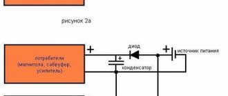
Simple high- and low-pass filters are shown in Fig. 2. In a high-pass filter (Fig. 2a), a capacitor in series is connected to a shunt resistor. In the low pass filter (Figure 2b), the capacitor and resistor are swapped.
Rice. 2. RC filter of the first order of high (2a) and low (2b) frequencies.
So, capacitors are often used to combine circuits, isolate unwanted noise in DC circuits and in frequency selective circuits (filters). Because capacitors store electrical charge, large ones are also used as reservoirs in AC and DC power supplies. In Fig. Figure 3 shows a typical power supply that includes a step-down transformer (which steps down the line voltage), a bridge rectifier (which converts the AC current from the transformer to pulsed DC current), and a pair of reservoir capacitors (which smooth out the ripple after the AC is rectified).
Fig.3. Schematic diagram of a full-wave power supply consisting of a step-down transformer, a full-wave bridge rectifier and two reservoir capacitors.
Similar circuits are found in many solid-state audio components. Similar solutions are used in lamp equipment, but due to the high voltages required to operate the lamps, the transformer here usually increases the mains voltage.
Reservoir capacitors used in transistor power amplifiers can be as large as 50,000 microfarads or more, while in other applications the circuit may use capacitors of 1 NF (one-thousandth of a microfarad) or even less. Thus, it is obvious that some types of capacitors are better suited for certain tasks than others.
Important clarification
As a rule, the largest reservoir capacitors are electrolytic, because they provide high capacity in a relatively small volume. These capacitors contain an electrolyte (liquid or gel) that chemically reacts with the metal foil inside the can to form a dielectric layer. Such electrolytic capacitors, as well as some others - for example, tantalum, are called polar, and failure to comply with the polarity of the connection can lead to their failure.
Another type is non-polar capacitors, which can be connected without regard to polarity. Such electrolytes were sometimes used in passive speaker crossovers, but this practice is now outdated as film capacitors do a better job, although they take up more space.
Capacitors can also have different pin arrangements - axial (axial) or radial. The advantage of radial electrolytes is that they occupy less area on the board, but their disadvantage is that they increase its height. Large electrolytic capacitors typically do away with solder pins in favor of screw terminals.
What do capacitors hide?
Real capacitors, like real capacitors, do not behave perfectly, and this is where the reason for their impact on sound quality lies. First, in practice, no capacitor is only a capacitance - it also has inductance and resistance. On a circuit diagram, a capacitor is usually indicated by one of the symbols in Fig. 4 (all of which visually refer to two separated plates), but in reality it is something like the circuit shown in Fig. 5. The resistor indicated in the figure as ESR (equivalent series resistance) may not be constant - the resistance may depend on frequency. In the case of electrolytic capacitors, ESR generally decreases with frequency.
Rice. 4. Options for designating capacitors in the diagram
One consequence of capacitors having inductance (ESL or equivalent series inductance in Figure 6) is that they are essentially electrically resonant. If we analyze the impedance of a capacitor as a function of frequency, it does not continue to decrease as frequency increases. In Fig. Figure 6 shows that the impedance reaches a minimum (equivalent to the ESR value) at the resonant frequency, and then, as the frequency increases, it begins to rise again due to ESL.
Rice. 5. Schematic equivalent of a real capacitor showing parasitic resistance (ESR) and inductance (ESL)
Rice. 6. Parasitic inductance causes capacitors to have electrical resonance, sometimes within the audible frequency range.
Large electrolytic capacitors typically have electrical resonance frequencies within the audio range. For small capacitors, electrical resonance frequencies can exceed 1 MHz. To increase the frequency of electrical resonance for a given capacitance, the ESL - series inductance - should be reduced.
To achieve this goal, various methods are used in the development of electrolytic capacitors, where this problem is most acute. For example, DNM T-Network capacitors use special foil T-junctions to reduce inductance - thus their resonant frequency is more than twice as high as a standard design (from 28 kHz to 75 kHz in the example given DNM on its website).
ESR has a potentially beneficial effect on damping the electrical resonance of a capacitor, however, unlike inductance or capacitance, resistance generates heat while current flows through the capacitor. In large capacitors, where the currents passing through them are large, this internal heating effect limits safe operating conditions. However, electrolytic capacitors work best when warm.
Microphone effect
It's no secret that lamp equipment is sensitive to vibration. Inside the evacuated glass shell of the lamp are thin metal electrodes, the distance between which affects the operation of the lamp. Thus, if you shake the lamp hard enough, it will affect its electrical output - an effect that is called "microphoning" because the lamp then behaves like a microphone.
Solid-state electronics are less susceptible to this effect, but to take one extreme example, the designers of early racing car engine management systems soon learned not to attach the electronic components to the engine, or to use good insulation, otherwise vibrations from the engine could interfere with its operation. The levels of vibration experienced by hi-fi equipment in everyday use are much lower, but some manufacturers, such as Naim Audio, still go to great lengths to minimize the likelihood of microphonic effects.
A capacitor's ability to store charge (its capacitance) is proportional to the area of the plates and inversely proportional to the distance between them, and the "plates" are usually thin foil with thin layers of dielectric between them. This causes capacitors to be susceptible to microphonic effects, as vibration can cause the distance between the plates and therefore the capacitance value to change.
Thus, the physical properties of the materials from which the capacitor is made can be as important as the electrical parameters. But what's even more interesting is that external vibration is not a necessary condition for capacitors to suffer from its effects, because forces generated by voltages and currents within the capacitor itself can also cause mechanical resonances. Because of this effect, you can even hear some capacitors making a sound when a signal passes through them. In a speaker crossover, where vibration levels, voltages, and currents are high, there is a “perfect storm” of factors that make selecting the appropriate capacitor a particularly important task.
Keywords
The problem of microphonic effect and mechanical resonances of capacitors has been actively discussed for many years, but there has been very little research on this issue. In any case, there are few published studies. But those that do exist support the view that this effect can have a noticeable impact on sound quality.
Additionally, in some cases, capacitors can produce unusually high levels of harmonic and intermodulation distortion. Understanding how and why this happens allows designers to focus their efforts on refining the circuitry and carefully selecting electronic components in a manner that will provide the greatest benefit.
How and where to install
According to manufacturers' recommendations, it is better to install tweeters as close to the listener's head as possible. This provides high-quality sound. However, it is not always possible to mount this device at the desired level. More often, when installing a device in a car with your own hands, you have to choose a location based on the existing features of the car and the already installed equipment.
It is extremely important that the speaker does not subsequently affect the usability of the vehicle. In addition, it is necessary to select a place so that the horn remains close to the radio. This will make it easier to connect.
The tweeter is often installed in the area of the corners of the mirrors. In this case, the speakers fit well into the existing interior of the car and do not cause discomfort while driving. In addition, localization on the front panel and windshield is possible.
Among other things, there are special stands that make installation easier. It is better to purchase podiums for tweeters together with this acoustic device, so as not to make a mistake with the size. If necessary, you can make them yourself.
In what places is it recommended to install tweeters?
Manufacturers recommend many places to place tweeters, most commonly at ear level. In other words, aim them as high as possible at the listener. But not everyone agrees with this opinion. This installation is not always convenient. It depends on the specific circumstances. And the number of installation options is quite large.
- Corners of mirrors. During the trip they will not cause additional discomfort. Moreover, they will fit beautifully into the interior of the vehicle;
- Dashboard. Installation can even be done using double-sided tape;
- Podiums. There are two options here. The first is to install the tweeters in a standard podium (which comes with the tweeter), the second is to make the podium yourself. The latter case is more complicated, but it guarantees a better result.
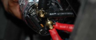
How to connect correctly
First, prepare the place where the horns will be installed. If necessary, a podium for tweeters is fixed. It is necessary to prepare cables and adapters. When installing horns, the connection is made using interconnect wires, and then cables for power supply are required.
Tweeters can be connected through an amplifier. This device is equipped with a number of connectors. Connecting horns to it is done in the same way as standard speakers. Each amplifier has its own connection features to the radio, which the manufacturer indicates in the technical documentation.
Alternatively, you can connect it directly to the main speaker or to the radio, but this method is considered less effective. It is convenient to use crossovers for tweeters during installation. This device is equipped with a number of clamps. It acts as a connecting link between the radio power source and the horns. In some cases, it is not possible to do without crossovers.
Hi all! In this post, I decided to raise a pressing and relevant topic for many beginners. Let’s try to understand it, delve into it, draw conclusions and formulate advice. Go!
We are talking about choosing capacitors for horn tweeters. This is exactly how all newbies pose the question. You and I are bally peppers and grated rolls, so let’s paraphrase this more correctly. Selection of a first-order passive high-pass filter for horn tweeters.
First, let's remember what kind of garbage this is, what is it for and how does it work? We need crossovers (filters) in order to cut off unnecessary sound frequency ranges from the speaker, giving it the bandwidth necessary for its normal operation. There is nothing terrible with subs in this regard. Even if you give the sub the whole stripe, nothing will happen to him. But when we talk about tweeters of any design, then for them the crossover will determine their life, sound and durability.
The second point that is important to understand: any crossover DOES NOT cut frequencies sharply. If your high-pass filter is set to, say, 3 kilohertz, this does not mean that the speaker will suddenly become silent below three. The speaker will sing at 2 and 1 kHz and 500 Hz and even 20! The whole question is how much power the signal will reach the speaker at these frequencies and how much and quickly the volume level will drop beyond the crossover setting. This moment is determined by the order of the crossover cut. 1st, order (6db/oct), 2nd (12db/oct), etc. What do these dB/oct mean? Well, with DB there are no questions. DB-decibels determine the volume level (more precisely, the sound pressure level, but that’s not the point) and oct. - this is an octave. An octave is... (it’s a simpler way to wrap it up :D) An octave is a range of frequencies located either up to twice the current frequency or half as low. It’s not clear, in short, one horseradish. :D:D I’ll explain with an example: Let’s say we have a 1st order high-pass filter at 1 kilohertz (1000 Hz). Such a filter passes high frequencies to the tweeter and cuts low frequencies. So, a first-order filter (6 dB/oct) means that below 1 kilohertz the sound will not disappear, but the volume of the sound will begin to fall. If we say our speaker sang with a volume of 100 decibels at 1 kilohertz, then below the filter setting by one octave (1000Hz/2=500Hz) at 500Hz the speaker will sing 6 decibels quieter. And another octave lower (500/2=250Hz) is already 12 decibels quieter, at 125Hz it’s 18 dB quieter, and at 63Hz it’s 24 dB quieter, and so on. If we cut the speaker at the same frequency but in the 2nd order (12 dB/oct), then at 500 Hz we would lose 12 dB, at 250 Hz 24 dB, at 125 Hz 36 dB and at 63 Hz 48 dB. This way you can calculate any filter order at different frequencies.
The example, of course, is extremely simplified and crude. The speed and uniformity of attenuation will depend on another 100,500 factors, but in principle, the example reflects the essence we need. Precisely because the tweeter will always sing below the cutoff frequency, it is highly not recommended to make a cutoff near their resonant frequency, below which it becomes extremely difficult for them to work. At best, this will reduce its volume significantly (you simply won’t be able to turn up the volume all the way without distortion). At worst, the tweeter will die. We learned this fact and moved on. Everything there is even more dreary and incomprehensible :D.
The next important aspect of this matter was completely leveled out in the minds of beginners by signs like this on the Internet:
Actually, the signs are correct. They would be... if not for one nuance. There are no 4 ohm, or 2 ohm, or 8 ohm speakers. And it never happened. ))
What is indicated on the speaker is not its resistance, it is the impedance, firstly, and secondly, it is the MINIMUM impedance that the speaker can have during operation. This criterion is very important for stable operation of the amplifier without overload. But this does not mean that the impedance cannot be higher when the speaker is operating. I’ll say more, it’s almost always higher, the whole question is by how much higher and when. (by the way, you can measure your 4 ohm speakers with a multimeter. There will always be a little less than 4 ohms. 3.7-3.8 ohms precisely because the impedance is indicated and you are measuring the resistance))). So, the impedance of the speaker when reproducing sound depends on a bunch of factors, starting from the design of the speaker itself and ending with the design of the speakers (and a horn tweeter is a tweeter in the design of a horn) and frequency. This last factor is especially interesting to us when we talk about HF. If, for example, you take two four-ohm tweeters and measure their impedance at, say, 5 kilohertz, then it can easily turn out that one tweeter at this frequency has an impedance of 5 ohms and the other has 7. Then, according to the table above, we try to cut them at 5 kilohertz with an 8 microfarad Conder. As a result, our first one will cut to 4 kilohertz, and the second with the same conder will cut to 3 kilohertz! Accordingly, the first one will simply make a sound of shit, the second one will start to burn. As an example, here is a graph of the system impedance versus frequency (Z characteristic) for component acoustics:
And here is a table of our teammate’s experimental measurements:
And HERE is the topic itself with measurements.
What conclusion can be drawn from this? And here’s this: If you read all the signs in a row and don’t use your head, then the sound of shit and scorched iron is your confident future.
To really find out the cutoff frequency of a capacitor and correctly select it, you can only have a graph of the dependence of impedance on frequency for your speakers or do it yourself in your conditions using a measurement method.
Another question is that no one really needs this and it’s much easier for everyone without thinking to crank up the Conder so that it hits louder. The overwhelming majority are supporters of just this approach, so let’s figure out how in this case not to mess up and screw everything up.
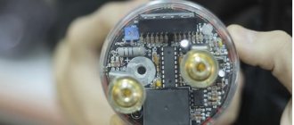
First, we need NON-POLAR capacitors. They usually look like this or similar:
It is highly not recommended to use such electrolytic conductors.
Their difference from the first ones is that they have polarity and work adequately in direct current. Those above work equally well in both variable and constant (and we are dealing with variable))). The Chinese are very fond of installing electrolytes in cheap systems by cutting off the tweeter with them. Hence, free advice for you: simply by replacing the electrolyte in your cheap acoustics with a non-polar capacitor of the same capacity, you can make the sound more pleasant and interesting)).
You need to start the selection FROM THE LOWER NOMINAL OF CAPACITORS TO THE HIGHER. The larger the capacitance of the capacitor, the lower it will cut your tweeter.
The capacitance rating of a capacitor is always indicated on its body, but sometimes this is done using a sophisticated algorithm. I won’t describe it, you don’t need it. I just recommend asking the seller in the store to put the Conders into different bags and sign each one.
Regarding the permissible operating voltage of capacitors, you don’t have to worry about it. For non-polar conductors, the permissible voltage is measured in the order of hundreds of volts, and in your tweeter it will work with a huge voltage reserve. )
That's actually all I wanted to tell you about capacitors for tweeters. It remains to be mentioned that the capacitor must be installed as close to the tweeter as possible. Ideally, solder directly to the demma. In this case, it does not matter at all which terminal the condenser will hang on. Although if you started hanging the Conder on the positive terminal, then hang it on the positive terminals and on all other foods.
Which capacitor to put on the tweeter
To obtain high-quality sound from speaker systems, you need to be very careful when choosing a capacitor. What kind of capacitor is needed for the tweeter speaker. Chinese manufacturers of inexpensive speakers use an electrolyte with a capacity of 2-10 microfarads in series with the high-frequency speaker coil.
Products of this type are polar and, by definition, are designed to operate on DC circuits. They do not behave entirely correctly on alternating current, so to connect a high-frequency speaker in an acoustic system of two or three loudspeakers, you need to use film products of appropriate capacity. If you have an inexpensive Chinese-made speaker system, then just open it and replace the electrolyte with a polypropylene or paper capacitor to feel the difference.
If the required capacitance is not available, then the necessary capacitors for the high-frequency speakers are assembled from several products connected in parallel. From domestic products, you can use K73-17 and K78-34. These are lavsan and polypropylene products. Type K78-34 is specially designed for installation in filters of high-quality acoustic systems. It operates correctly at frequencies up to 22 kHz with speaker output power up to 220 watts with 4 ohm speakers.
To choose the right capacitor for a 4 Ohm tweeter, you need to know its resonant frequency. High-frequency drivers can have a relatively low resonant frequency of about 800-1200 Hz, but most tweeters will resonate at 2000-3000 Hz. The capacitor values for different cutoff levels to a 4 ohm speaker are as follows:
- 5,000 Hz – 8.0 µF
- 6000 Hz – 6.5 µF
- 8000 Hz – 5.0 µF
- 9000 Hz – 4.4 µF
You need to cut the band using a first-order filter above the resonance, otherwise the speaker will vibrate unpleasantly when playing sound. It is recommended that the filter cutoff frequency be approximately twice the resonance value of the tweeter.
Which ones are better to choose?
Silk tweeters were previously thought to provide the best sound results. But the products of a number of brands have proven in practice that quality can be achieved without the use of silk. First of all, the sensitivity of the subwoofer plays a role in providing good sound quality.
How to connect
The tweeter reproduces sound from 3000 to 20,000 hertz and is one of the main elements of a stereo system. The radio has a larger frequency range from 5 to 25,000 hertz. When a tweeter is supplied with a low-frequency signal for which it is not designed, it may stop functioning correctly or break completely.
To increase durability and reliability, tweeters are removed from low-frequency sounds and modified so that only the desired range of sound frequencies is delivered to it.
Exceptions are those cases when the car owner bought a used radio without a capacitor. The capacitor looks like a small box to which the signal is sent, or it is mounted on a wire or built into the tweeter itself. The frequency range depends on the type of capacitor and when purchasing, you need to make sure that you are purchasing the right one.
A high-quality sound reproduction system that allows you to create the effect of presence - horn acoustics. Such systems are installed both as home acoustics and in cars, allowing you to create the atmosphere of a large concert hall in a limited space and convey the emotions of the performer to the listeners. How to properly connect a speaker to a car?
Horn acoustics
Ceramic capacitors
Types and properties of ceramics
This type of capacitor refers to capacitors with an inorganic dielectric. Ceramic capacitors are the most popular type of capacitors, due to their high and stable characteristics, ease of production, and suitability for automated installation [1]. Ceramic capacitors get their name because they use radio frequency ceramics based on titanium, zirconium and oxides of other materials as a dielectric. Most commonly, RF ceramics are made from titanium dioxide (TiO2), barium titanate (BaTiO3), or strontium titanate (SrTiO3), although the exact ceramic formulas vary between manufacturers.
Now it is necessary to say a few words about the classification of ceramic capacitors. Quite often, the “ultimate goal” of a review article on electronic components is an attempt to provide the developer with a universal tool for selecting components for use in a specific application, based on classification according to various parameters. In relation to ceramic capacitors, attempts to create a classification “to help the developer” must be considered rather unsuccessful. There is more than one reason for this, and the bottom line is that it would be more correct to admit that the most reliable way to select ceramic capacitors for a specific application is to read the datasheet.
Suffice it to mention that two engineering communities have proposed their own versions of the classification: IEC (International Electrotechnical Commissiom) and EIA (Electronic Industries Alliance). Classifications have differences. Thus, the EIA divides ceramics into four classes, and the IEC into three. The fact that a significant portion of manufacturers (mostly American) use the EIA classification to label their products, while others use the IEC classification, only complicates the task of selecting components. It should be added here that the IEC encoding is also called Industrial, although in essence both encodings operate in the industrial temperature range. There is also a separate Military encoding. This section of the article will mainly refer to EIA and Industrial encodings.
There have been attempts at classification based on the division of capacitors by application, in which, however, it can be seen that the division by application is predominantly related to frequency. The same EIA proposes dividing ceramic capacitors into two large classes. One can rather roughly distinguish between higher-frequency applications (resonant circuits, etc. equipment), where low losses and high capacitance stability are of considerable importance, and less high-frequency applications (filtering circuits, etc.), where these parameters are not so significant ([1] , EIA).
Ceramic capacitors are capacitors with a standardized TKE value. As mentioned, the Electronics Industry Association (EIA) divides ceramics into four classes and types within each class. The lower the class number, the higher the overall performance of the capacitor, but the larger the size for a given capacitance. The types within each class define the recommended operating temperature range and TKE, including temperature drift and tolerance in said temperature drift. EIA defines the basic parameters of capacitors for each class and methods for measuring them. This applies to insulation resistance, dielectric loss tangent, dielectric absorption and other basic parameters of capacitors.
The division of ceramic capacitors into classes is quite arbitrary, since strict requirements for each class are not specified.
For example, class 1 capacitors are considered to be “precise temperature-compensated capacitors with high stability in voltage, temperature and frequency.” Class 1 capacitors are characterized by a temperature coefficient of no worse than ±3% per degree at +25…+85 °C. For Class 1 capacitors, an accuracy of 1% can be achieved, although an accuracy of 5–10% is considered most typical. The temperature dependence of capacitance for class 1 capacitors is considered linear. Ceramic capacitors are divided into classes according to the type of ceramic used in their manufacture. The EIA has introduced a set of codes to identify ceramic types. The codes for class 1 and class 2 ceramic capacitors are different. In addition, there are two options for designating the type of ceramic - in accordance with the EIA-RS‑198 standard and the Industrial standard mentioned above. Table 1 shows the EIA coding for Class 1 ceramics. Table 1. EIA-RS‑198 coding of ceramics according to the slope of the temperature curve (class 1)
| Temperature coefficient (slope of temperature curve) | Temperature coefficient multiplier | Permissible temperature coefficient deviation, +25… +85 °C | |||
| Letter | ppm/°С | Number | Factor | Letter | ppm/°С |
| C | 0 | 0 | –1 | G | ±30 |
| B | 0,3 | 1 | –10 | H | ±60 |
| L | 0,8 | 2 | –100 | J | ±120 |
| A | 0,9 | 3 | –1000 | K | ±250 |
| M | 1 | 4 | +1 | L | ±500 |
| P | 1,5 | 6 | +10 | M | ±1000 |
| R | 2,2 | 7 | +100 | N | ±2500 |
| S | 3,3 | 8 | +1000 | ||
| T | 4,7 | ||||
| V | 5,6 | ||||
| U | 7,5 | ||||
For example, C0G ceramics are most often used in class 1 capacitors.
This means that in the temperature range of +25...+85 °C the slope of the temperature curve will be zero (0), that is, there will be no dependence of the capacitance on temperature. This can be seen in Fig. 1, 2, where the C0G capacitors are designated NP0 (the designation used in the Industrial standard). The temperature coefficient multiplier, together with the coefficient itself, also determines the slope of the temperature curve and, accordingly, the degree of change in capacitance due to temperature variations. In our example (C0G), a coefficient of 1 will not change the slope of the temperature curve specified by the main temperature coefficient (0), which in English literature is often called Significant Figures. The sign in front of the temperature coefficient multiplier determines the direction of change in capacitance: the “–” sign indicates that with increasing temperature the capacitance will decrease. The effect of the sign on the temperature coefficient multiplier is clearly demonstrated in Fig. 1. An explanation needs to be made for the drawing. The ceramic industry designation, based on the Negativ/Positive designation, is considered more outdated than the EIA designation, but is more intuitive and consists of a letter (N for negative temperature coefficient, P for positive temperature coefficient) and a number , indicating the temperature error. A comparison of EIA and industrial encoding can be seen in Table 2. Table 2. Comparative EIA and Industrial encoding
| Industry | P100 | NP0 | N030 | N075 | N150 | N220 | N330 | N470 | N750 | N1500 | N2200 |
| EIA | M7G | C0G | B2G | U1G | P2G | R2G | S2H | T2H | U2J | P3K |
Now, actually, fig. 1, which was mentioned above. It shows the change in capacity as a function of temperature for class 1 ceramics. The various ceramic materials in this figure are Industrial coded (colored) and can be found in Table 2 to match their EIA codes (black boxed symbols). When comparing tables 1 and 2, one can see the effect of the sign of the temperature coefficient multiplier, illustrated in Fig. 1.
Rice. 1. Idealized curves of the dependence of capacity on temperature of class 1 ceramics
The main difference between class 2 ceramics and class 1 is the nonlinear dependence of capacity on temperature. This is clearly visible in Fig. 2, which compares ceramics of the 1st class C0G (NP0) with two samples of the 2nd class (X7R, Y5V). In general, class 2 capacitors have greater volumetric efficiency, which is associated with the high dielectric constant of class 2 ceramics and is directly reflected in the size of the capacitors.
Rice. 2. Comparison of the temperature characteristics of ceramics of the 1st and 2nd classes
The EIA temperature coding for Class 2 capacitors is shown in Table 3.
Table 3. EIA-RS-198 coding for ceramics without temperature compensation (Class 2 and higher)
| Lowest operating temperature | Highest operating temperature | Changing Capacity | |||
| Letter | Temperature, °C | Number | Temperature, °C | Letter | V % |
| X | –55 | 4 | +65 | A | ±1 |
| Y | –30 | 5 | +85 | B | ±1,5 |
| Z | +10 | 6 | +105 | C | ±2,2 |
| 7 | +125 | D | ±3,3 | ||
| 8 | +150 | E | ±4,7 | ||
| 9 | +200 | F | ±7,5 | ||
| P | ±10 | ||||
| R | ±15 | ||||
| S | ±22 | ||||
| T | +22/–33 | ||||
| U | +22/–56 | ||||
| V | +22/–82 | ||||
In addition to the temperature dependence described above, class 2 ceramics also have a clear dependence of capacitance on the applied constant or slowly varying voltage. The essence of this phenomenon is that when a constant voltage is applied to ferroelectrics used as ceramics in class 2 capacitors, the dielectric constant decreases due to polarization effects. As a consequence, the capacitance associated with the dielectric constant decreases. In English-language documentation, this phenomenon is often described by the term DC-bias (direct current bias).
This property is almost never mentioned when trying to classify capacitors, and specific values for the change in capacitance can be obtained mainly by studying the technical documentation for a specific product.
It should also be noted that a significant contribution to the description of this phenomenon was made by employees of the Japanese company Murata. They conducted research on domain structures of ceramics and proposed interactive software for hardware engineers to take DC bias into account when designing. In Fig. 3 you can see an example from Murata - here is the dependence of capacitance on DC voltage for class 2 ceramic capacitors (X5R, X7R).
Rice. 3. An example of the dependence of the capacitance of ceramics X5R, X7R on the applied constant voltage (Murata)
The direct correspondence between the type of ceramic and the frequency range is indicated in the technical documentation for a particular capacitor.
It is believed that class 1 capacitors are higher frequency and have the lowest losses and the least dissipation in the upper high-frequency range. Nevertheless, class 1 capacitors have a direct relationship between the maximum operating frequency and the capacitor rating. This can be seen in Table 4 when comparing the two types of ceramics in the frequency domain. Table 4. Comparison of ceramics of 1st and 2nd classes
| 10 pF | 100 pF | 1 nF | 10 nF | 100 nF | 1 µF |
| C0G (class 1) | 1550 MHz | 460 MHz | 160 MHz | 55 MHz | |
| X7R (Class 2) | 190 MHz | 56 MHz | 22 MHz | 10 MHz |
And it should be borne in mind that dielectrics of the 2nd, 3rd and 4th classes are piezoelectrics, and therefore capacitors of these classes are susceptible to the microphone effect. This must be taken into account when deciding on the use of capacitors of these classes at frequencies above 200 MHz. But when such capacitors are used in power supplies, even pulsed ones, the microphone effect does not appear so clearly, except when the operating frequency is in the audio range. The influence of the piezoelectric effect on ceramics of the 2nd class is less than on ceramics of the 3rd and 4th classes. The presence of the piezoelectric effect in most types of ceramics used in the production of ceramic capacitors requires, when designing electrical circuits with ceramic capacitors, mandatory consideration of the reactive power dissipated by the capacitors, since in conditions when the reactive power is equal to or exceeds the active power dissipated by the capacitors, rapid aging occurs ceramics with its subsequent destruction. This is especially important when ceramic capacitors are used in power or filter circuits, such as power supply circuits for computer processors.
In addition to classification by type of ceramic, ceramic capacitors are ranked by design. The following groups of ceramic capacitors are distinguished:
- polymer-coated disk capacitors for printed circuit mounting (disk);
- single layer ceramic capacitors (single layer);
- multilayer rectangular capacitors for surface mounting (multilayer);
- packageless disk capacitors for surface mounting for use in the UHF range (decimeter wave range);
- Tubular capacitors for printed circuit mounting are currently used extremely rarely.
Single Layer Ceramic Capacitor (SLCC)
In the class of ceramic capacitors, the type of so-called single-layer, or monolithic, capacitors should be noted.
Because SLCC uses the same ceramics, conductive materials, and many of the same technologies as multilayer capacitors, there are significant similarities in the temperature and frequency properties of MLCC and SLCC.
Single-layer ceramic capacitors are in some ways an elementary classical capacitor, since their design consists of two electrodes, between which a layer of high-frequency ceramics is located (Fig. 4).
Rice. 4. Dielectric Laboratories Single Layer Capacitor Design
Capacitors of this type are produced using the technology of sintering dissimilar materials and are, in fact, a ceramic-metal composite alloy. Therefore, they are intended primarily for use in integrated assemblies, including microwave ones. Although some manufacturers, for example Vishay, use the same technology to produce disk capacitors (Disk) for printed circuit mounting. The undoubted advantages of single-layer monolithic capacitors include:
- very low transmission losses and low scattering at frequencies up to 50 GHz;
- operating frequency range: up to 100 GHz;
- reliable and durable design, including resistance to fracture;
- nominal capacitance: 0.04–6200 pF;
- dielectric constant of ceramics: 14–25000;
- operating voltage: up to 100 V.
Classification of single-layer capacitors
There are several options for classifying single-layer capacitors. One of them is used by Dielectric Laboratories. It includes the following types:
- Border Caps are conventional flat-plate broadband capacitors with reduced metallization on one or two sides. Reducing the metallization area helps prevent shorting of the plates during installation and improves visual inspection. The appearance and types of such capacitors are shown in Fig. 4.
- Di-Cap are ordinary flat-plate broadband capacitors, the metallization area of which is equal to the area of the ceramic. Used in the frequency range 100 kHz – 80 GHz. The same type of capacitors can be output (Fig. 5).
- Gap Cap - two series-connected capacitors on one ceramic plate (Fig. 6). Capacitors of this type can be connected in series to a microstrip line without the use of conductors.
- Bar Cap1—capacitor assemblies. The main range of applications is up to 30 GHz. Manufactured for use, inter alia, in monolithic microwave integrated circuits (MMIC), Fig. 7.
- Bi-Cap (Binary-Cap) - several capacitors on one ceramic plate. Capacities are related as powers of two. The main range of applications is up to 30 GHz. Used for prototyping and fine-tuning circuits. They have dimensions comparable to the geometry of components used in microwave devices. Capacitors on one plate can be used either singly or in combination (Fig. 8).
- T‑Cap is a series of capacitors similar to Di-Cap. Has a different size range.
- Milli-Cap - surface mount capacitors.
Rice. 5. Di-Cap Lead Capacitors from Dielectric Laboratories
Rice. 6. Gap-Cap by Dielectric Laboratories
Rice. 7. Bar-Cap by Dielectric Laboratories
Rice. 8. Bi-Cap from Dielectric Laboratories
Of interest is the comparative frequency response of several types of single-layer capacitors, shown in Fig. 9. Next, a similar diagram will be presented for multilayer capacitors.
Rice. 9. Comparative frequency response of different types of single-layer capacitors
Application of SLCC
Due to the low capacitance values due to the design of the classic single-layer capacitor and the outstanding frequency properties of ceramics, SLCCs have become most widespread in high-frequency and microwave applications. The use of ceramic types with high dielectric constants allows us to support the trend towards permanent miniaturization of this class of capacitors. A clear illustration of this can be found in the materials of the AVX company [2] (Fig. 10).
Rice. 10. Miniaturization of SLCC [1]
A typical example of properties that meet modern requirements for microwave components can be considered a series of ultra-wideband blocking single-layer ceramic capacitors GX from AVX [2]. The products are characterized by ultra-low insertion loss and low return loss. They are used in the frequency range up to 40 GHz and voltages up to 50 V, have capacitances up to 100 nF and form factor 0603-0201. In Fig. Figure 11 shows a typical insertion loss graph for the GX0S series.
Rice. 11. Insertion loss (S21) for GX0S (AVX) series blocking capacitors
Purpose
In most cases, horn acoustics are designed to reproduce mid and high frequencies, allowing you to improve existing acoustics. The best effect is achieved when used with a subwoofer (amplifier) that reproduces low frequencies.
By adding and changing audio system components, you can achieve the desired sound in your car, and horns are excellent equipment to improve the quality of music in your car.
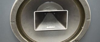
Horn
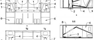
One popular place to connect horns is at the front of the car. The horns are installed frontally on the housing wall. A waveguide is formed inside with a hole facing outwards.
To properly connect the horn to the radio, you need to use a capacitor. It is also recommended to carry out sound adjustments to properly distribute the sound and achieve maximum immersion.
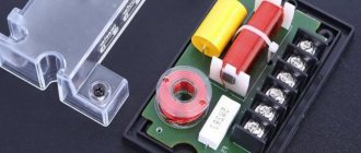
Capacitor
Installation
How to install and connect a horn without an amplifier directly to the radio? The first step is to make or purchase a podium for the speakers.
Speaker podiums
In most cases, the podium is supplied with the column, but in some cases you need to make it yourself. This does not require special knowledge, and it is enough to simply measure the dimensions of the speaker and cut a podium to fit these dimensions. When you lack knowledge or tools, it is recommended to contact a specialist.
Horns are installed in two ways:
- Diagonally - the right speaker is directed to the left seat, and the left, respectively, to the right.
- Direct – the speakers are sent directly to the listener.
The options are equivalent to each other and when choosing, you need to rely only on the layout of the car’s interior and audio system. It is recommended to try two variations, and only after that make a final choice.
The installation location depends on the location of the audio system, and in most cases, it is selected individually for each speaker.
Application of capacitors in RF and microwave
In high-frequency applications, capacitors based on ceramic, glass and organic dielectrics are most widely used. Among the latter, the most widely used products are those based on dielectrics made of polycarbonate, polyester and polypropylene. Also in the current decade of this century, capacitors using silicon materials and technologies have seen significant development.
Let's look at the most common and widely used types of capacitors today. In connection with the development of new microminiaturization technologies and their widespread use not only in special industries, but also in household appliances, one of the most common types of capacitors are ceramic capacitors.
Connection
Installing additional equipment and making podiums is half the battle. Installed devices need to be connected. How to connect a horn through a standard radio or speakers?
When the connection is made directly to the radio (without an amplifier), you need to use a capacitor, which is a filter for certain frequencies. It allows you to increase the life of the speakers, but its capabilities are limited. When purchasing new equipment, the capacitor is included in the kit, but if it is not there, you need to select and purchase it yourself. The horns are connected directly to the terminals of the radio, but a capacitor must be installed on the plus.
You can connect the horn to the speakers in the same way as conventional speakers. The plus is connected to the positive wire (via a capacitor), and the minus is connected to the negative.
You can connect the horn to the amplifier according to the principle of conventional speakers, and there are no differences in connection. The amplifier itself is installed according to the diagrams specified in the equipment instructions. In most cases, the connection is made with special wires (interconnect) to the radio, and then power wires (power) are connected. After this, connect the speaker wires to the speakers or subwoofer, observing the polarity.
Another type of connection is through a crossover. This is a device for separating a signal by frequency. It is most often made in the form of a separate unit and is perfect for connecting a multi-component audio system.
When connecting, you must comply with all safety requirements.