Daisy chaining of speakers
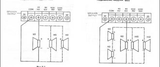
With a daisy chain connection (Figure 1), the speakers are connected in series, one after the other. It is very important to phase the speakers correctly, connecting the plus of one speaker to the minus of the other. When connected in series, the total resistance increases and the output power decreases. This method can be used to reduce the output power of a channel that is supporting the sound of others, such as the rear or center channels. It is better to connect no more than two speakers in series, since more speakers will greatly reduce the output power. You cannot connect speakers with different impedances, for example, four- and eight-ohm, since in this case each of them will have a different volume. Only exactly identical speakers can be connected in series, because different speakers can also have different resistances in the 0.5 Ohm range.
When connected in series, the speaker impedance is calculated using the formula:
R = R1 + R2
,
where R is the resistance that we get as a result of such a connection, and R1 and R2 are the resistance of speakers 1 and 2. The resistance of more speakers is calculated similarly: R = R1 + R2 + R3 + ... + Rn
, i.e. resistances are summed up.
The reduction in power due to increased load is calculated using the formula:
P = Preal (Rreal/Rcurrent),
where P is the power at a changed load, Preal is the rated power of the amplifier at standard resistance, Rreal is the load resistance at which the real power of the amplifier was measured (rated load resistance), Rcurrent is the total resistance of the speakers that we obtained. This formula can be used for any of the three types of connection described, and with its help it is easy to calculate the increase or decrease in amplifier power due to non-standard load.
Parallel connection of speakers
When speakers are connected in parallel (Fig. 2), the output power increases and the resistance decreases. When connecting two four-ohm speakers in this way, their combined impedance will be 2 ohms, and you need to know whether the amplifier can handle such a low load. Much more often you come across amplifiers that can operate normally with a resistance of 2 ohms than with 1 or 0.5 ohms - the latter are already very rare.
Connecting a load impedance lower than its rated value to the amplifier may damage the device. But if the amplifier previously operated with a resistance of four ohms, and can operate at two ohms, now it will produce much more power for such a load and may need a more powerful power supply! For example, if previously the amplifier needed four amperes for power supply, now to double the power it will need about eight amperes (i.e. twice as much).
You can calculate the resistance that will be after connecting the speakers in parallel using the formula:
R = (R1 R2) / (R1 + R2),
where R is the load resistance for the parallel connection we are looking for, and R1 and R2 are the resistances of the speakers that are connected in this way. For example, the resistance of two eight-ohm speakers connected in parallel would be 4 ohms [(88)/(8+8) = 4 ohms]. When two speakers are connected in parallel, the output power of the amplifier for such a load will be twice as large.
Speaker combo connection
This connection diagram (Fig. 3) is used to obtain the required resistance for the amplifier. For example, in order to connect four speakers with a total impedance of 4 ohms. To calculate the load resistance using this connection method, use the formula:
R = (R1+2 R3+4) / (R1+2 + R3+4),
where R12 is the total resistance of speakers 1 and 2, which are connected in series, and R34 is the same for speakers 3 and 4. If you have four 30-watt 4-ohm speakers, then with this wiring diagram the total power will be 120 watts and the resistance will be still the same 4 ohms. And the power supplied from the amplifier will be equally divided among the four speakers.
For more speakers we use the formula
1/Rpar=1/ R1+1/R2+1/R3+1/R4+1/R5
……. for parallel connection of speakers with the same resistance can be calculated using f.
Rpar = Rnom./ n
, where n is the number of speakers
Calculation example: You need to connect 2 speakers with two coils of 2 ohms
Option 1, (the best) we connect both coils of one speaker in parallel, we get 2/2 = 1 Ohm, we connect in series with the second speaker, which also has coils connected in parallel and we get 2 Ohms. 2/2+2/2= 2Ohm
Option 2: connect all coils and speakers in series 2+2+2+2=8 Ohm,
Option 3: we connect the coils in series and the speakers themselves in parallel, (2+2)/2= 2 Ohm.
Option 4: all the coils of both speakers are parallel, 2/4 = 0.5 Ohm, think for yourself, to connect this way, you need a very good power supply to the amplifier.
do not use different speakers in such connections, especially with different impedances!
Options for load resistance when connecting speakers to an amplifier
To connect, for example, four speakers, you need to use one four-channel or two two-channel amplifiers for them. However, sometimes it is not possible to install another amplifier, and it is necessary to increase the number of speakers. For example, it may be necessary to connect four (2 per channel) or eight speakers (4 per channel) to the amplifier. In such cases, three connection methods are used: serial, parallel and combined (a mixture of the first two). The most important thing is to find out what the minimum allowable load resistance of the amplifier is and, based on this, choose the connection method.
Daisy chaining of speakers
In
It is very important to phase the speakers correctly, connecting the plus of one speaker to the minus of the other. When connected in series, the total resistance increases and the output power decreases. This method can be used to reduce the output power of a channel that is supporting the sound of others, such as the rear or center channels. It is better to connect no more than two speakers in series, since more speakers will greatly reduce the output power. You cannot connect speakers with different impedances, for example, four- and eight-ohm, since in this case each of them will have a different volume. Only exactly identical speakers can be connected in series, because different speakers can also have different resistances in the 0.5 Ohm range. When connected in series, the speaker impedance is calculated using the formula:Where R is the resistance that we get as a result of such a connection, and R1 and R2 are the resistance of speakers 1 and 2. The resistance of more speakers is calculated similarly: R = R1 + R2 + R3 + ... + Rn, i.e. resistances are summed up.
The reduction in power due to increased load is calculated using the formula:
P = Preal (Rreal/Rcurrent),
Where P is the power at a changed load, Preal is the rated power of the amplifier at standard resistance, Rreal is the load resistance at which the real power of the amplifier was measured (rated load resistance), Rcurrent is the total resistance of the speakers that we obtained. This formula can be used for any of the three types of connection described, and with its help it is easy to calculate the increase or decrease in amplifier power due to non-standard load.
Parallel connection of speakers
When
When connecting two four-ohm speakers in this way, their combined impedance will be 2 ohms, and you need to know whether the amplifier can handle such a low load. Much more often you come across amplifiers that can operate normally at a resistance of 2 ohms than at 1 or 0.5 ohms. Connecting a load impedance lower than its rated value to the amplifier may damage the device.You can calculate the resistance that will be after connecting the speakers in parallel using the formula:
R = (R1 R2) / (R1 + R2),
Where R is the load resistance for the parallel connection that we are looking for, and R1 and R2 are the resistances of the speakers that are connected in this way. For example, the resistance when connecting two eight-ohm speakers in parallel will be 4 ohms. When two speakers are connected in parallel, the output power of the amplifier for such a load will be twice as large.
Speaker combo connection
This
For example, in order to connect four speakers with a total impedance of 4 ohms. To calculate the load resistance using this connection method, use the formula: R = (R12 R34) / (R12 + R34), where R12 is the total resistance of speakers 1 and 2, which are connected in series, and R34 is the same for speakers 3 and 4. If If you have four 30-watt four-ohm speakers, then according to this connection scheme the total power will be 120 W and the resistance will be the same 4 ohms. And the power supplied from the amplifier will be equally divided among the four speakers.Online calculator
http://www.rockfordfosgate.com/rftech#wiringwizard
The most important task when turning on the speakers is to connect them correctly so that none of them is overloaded, since overloading can easily damage any speaker. It is important to know and follow the rule that states that power should be supplied to the speaker either lower than or equal to the rated (design) power. Otherwise, sooner or later even the most excellent and branded speaker will fail.
Let's look at the simplest way to connect speakers - in series, let's look at the diagram:
When the speakers are connected in series, their resistance is summed, so we get a total resistance of 32 ohms. This is a fairly large resistance, so if you connect it to an 8-ohm ULF output, then due to the high resistance, the current through the speakers will flow low and they will not sound loud. The amplifier and load will not work efficiently.
For speakers, the total resistance is calculated using this formula and in our case we get 2 Ohms. You cannot connect such a composite cascade to an 8-ohm ULF, otherwise the amplifier will simply burn out, so let’s look at the most common method
This example of connecting speakers is already suitable for an 8-ohm amplifier. By analogy, you can assemble a composite speaker for any required resistance.
In addition to the above, when connecting several speakers, it is advisable to take into account the polarity so that they work in phase (in coordination). To do this, the manufacturers indicate the polarity (“+” and “-”) on the terminals. In the case of monophonic sound reproduction, polarity can be neglected, but with stereophonic sound reproduction, coordinated inclusion plays a very significant role. Because it is required that the diffusers of each speaker oscillate synchronously.
If the speakers do not work in harmony, then distortion and displacement of the sound picture will occur, since sound waves during propagation will partially compensate each other, and during in-phase operation, sound vibrations will be summed up, creating a real and most complete sound atmosphere.
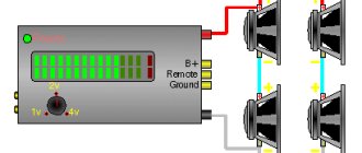
When the speakers are connected in parallel, their positive “+” terminals are connected together and connected to the “+” audio output of the ULF. We connect the negative one in the same way.
When connected in series, the phasing of the speakers will be slightly different.
When assembling and adjusting acoustic devices yourself, you should remember that if you use low-pass or high-pass filters, they can change the phase of the signal to the opposite one.
Many car owners without technical education do not know how to connect an amplifier to a car radio - for them it seems like too much of a time-consuming task. In fact, you shouldn’t rush to contact a car service center, since installing a car amplifier is not so difficult.
Maintenance by specialists will be expensive, so in order to save money, it is worth trying to understand the connection procedure, which this article will help with.
For high-quality operation of the amplifier you need:
- Give him good food;
- Give a signal from the radio. We looked at how to properly connect the radio;
- Connect speakers or subwoofer.
More details on how to connect the amplifier can be found below.
Theory. Connection types
In electrical engineering there are two types of connections - series and parallel. With a series connection, the resistance is summed up; with a parallel connection, it becomes lower than the smallest of the connected ones. This is something worth remembering and will come in handy in order to connect your speakers correctly.
Basic formulas for parallel and serial connections
There is also a mixed connection. This is when serial chains and parallel connections are “mixed”. In this case, calculation formulas are used, gradually arriving at one of the “pure” circuits - parallel or sequential.
Mixed compound and its conversion to "simple"
The figure shows the sequential transformation of a complex mixed connection into a simple one.
How to connect
If you expect to be told to connect only in parallel or only in series, you are in vain. The connection diagram is selected individually. There are two main points to take into account:
- Amplifier power.
- Amplifier load resistance.
Implementation of parallel connection
If you have an amplifier of a certain power and there are speakers suitable for it, this is good. But it happens that for the amplifier you need to select a load from several available speakers of different power. This is where you need to understand how to connect speakers in series, parallel or mixed so as not to exceed the parameters.
How to connect speakers - in series or in parallel? And so and so. Depends on what speakers you have. Or rather, with what power and resistance. What is also important is the output power of the channel and how many speakers you want to “hang” on each channel.
Determine the power and resistance of the speakers
It’s quite simple here, but we’ll still give a few examples. These markings are usually marked on the back of the case or basket. The photo shows the parameters of the speakers.
Designation of power and resistance on the speaker
Typically, long-term power is indicated, that is, the value at which the dynamic head is able to operate for a long time. At the same time, MAX POWER is indicated on the ALPHARD head - maximum power. This is peak power, its speaker can withstand, for example, a second.
On old domestic speakers the designations are slightly different. For example, in the figure below 2GDSH-3.
Designations on Soviet speakers
The first digit indicates the power of the product. Further, the head is dynamic broadband and its resistance is 8 ohms. So, we’ve sorted out some parameters, let’s move on.
Correct speaker connections
The peculiarity of connecting speakers is that they have positive and negative inputs. They need to be somehow connected to the inputs of the amplifier, and also somehow connected to each other.
Proper parallel and series connection of speakers
Connecting interconnect wires and control (REM)
To lay the cable, you need to find the linear output on the radio. The linear output can be recognized by the characteristic “bells” that are located on the rear panel of the radio. The number of linear outputs differs in different radio models. Usually there are from one to three pairs. Basically they are distributed as follows: 1 pair - you can connect a subwoofer or 2 speakers (labeled as SW\F) If there are 2 pairs of them, you can connect 4 speakers or a subwoofer and 2 speakers (outputs are labeled F and SW), and when there are 3 pairs of linear ones on the radio wires you can connect 4 speakers and a subwoofer (F, R, SW) F This is Front i.e. front speakers, R Read rear speakers, and SW Sabwoorer I think, and so everyone understands what.
Does the radio have no line outputs? Read the article "".
The connection will require an interconnect wire, which should never be skimped on. It is prohibited to lay the interconnect cable near the power wires, as various types of noise will be heard when the engine is running. You can run the wires both under the floor mats and under the ceiling. The latter option is especially relevant for modern cars, in the interior of which there are electronic accessories that create interference.
You also need to connect the control wire (REM). As a rule, it comes with interblock wires, but it happens that it is not there, purchase it separately; it does not need to be of a large cross-section - 1 mm2 is quite enough. This wire serves as a control for turning on the amplifier, i.e. when you turn off the radio, it automatically turns on your amplifier or subwoofer. As a rule, this wire on the radio is blue with a white stripe; if it is not there, use a blue wire. It is connected to the amplifier to a terminal called REM.
Daisy chaining of speakers
A daisy chain connection is when they are switched on one after the other, like carriages. If you look at the diagram, the wires are connected like this. We feed the minus from the output of the amplifier to the minus of speakers A, and the plus to the plus of loudspeaker B. And we connect their free inputs (plus at A and minus at B) to each other.
Connecting speakers in series: resistance adds up, output power drops
Please note that the impedance of the speaker chain increases. It is summed up from all components. In the example, two 2 Ohm speakers are connected in series. The total resistance is already 4 Ohms. This connection is good if the amplifier cannot operate with a low-impedance load. Low resistance is 2 ohms and below. In this case, either speakers with a higher resistance are connected, or low-impedance ones are connected in series.
How to connect three or more speakers in series
How to connect three speakers in series to one channel? Yes, everything is the same - one by one. Minus, apply to minus first (A); plus - to the plus of the third C (or last). We connect the free plus from element A to the minus of element B. Then we feed plus B to minus C. So we get a chain of three speakers connected to one channel.
How to connect 3 speakers to 1 channel in series
If you need to connect four or more fragments in series to one channel, simply insert them in the middle. Don't forget that circuit resistance adds up. With each new element in the chain it becomes larger.
Power in series connection
As the resistance increases, the output power will drop. How many watts will each speaker receive when connected in series? And you can count. There is a formula - it is in the picture.
Input power is the power that the amplifier will put into the channel, that is, what we are trying to calculate. The measured power is that indicated in the characteristics (what goes into the channel according to the passport data). And Zr is the resistance at which the power was measured. It is usually written in the characteristics as the minimum load on the channel. And the total resistance is the resistance of the speakers that you plan to “hang” on this channel.
Formula for calculating the actual power supplied to the amplifier channel
Let's apply the formula with an example. Let us have a 2-channel amplifier that outputs 100 W (2*100 W) to each channel. It cannot work with low-resistance loads (2 Ohms and below). Therefore, it was decided to connect two speakers with a resistance of 2 Ohms in series for each channel. We substitute the data into the formula: 100 W * (4 Ohm / 8 Ohm) = 100 W * 0.5 = 50 W. This is what will go into each channel.
The power of the speakers must be selected so that it is 10-20% higher than the power that will be received by it. In this case, any loudspeaker will work for a long time. And if you take the power “back to back”, then even the highest quality speaker will very soon wheeze and will need to be replaced .
Since there will be two loudspeakers on the channel with the same parameters, the channel power will be divided in half. So we get that each speaker will receive 25 watts. If you add the desired power reserve, you will have to look for speakers with a power of at least 30-35 W.
Three-way front and subwoofer
You can safely connect loudspeakers to an amplifier with an output voltage of 30V, but the loss of power in actual volume will be completely unacceptable. However, such inclusion is not used in first-order filters, since in this case an AC short circuit will occur at frequencies above or below the cutoff frequency, respectively. When connected in series, the phasing of the speakers will be slightly different. It is much more difficult if there are two voice coils or you need to connect several subwoofers. The main feature of broadcast systems is the use of a matching transformer in the amplifier, which outputs a signal with level B into the line; in some cases it can be 30V, V, but we will consider these cases separately.
The improved car audio connection diagram involves the use of 3 toggle switches, one 2-pin and two 6-pin. Mid-range speaker 15GD
Knowing the intricacies of all the ways to connect speakers to each other and other participants in the speaker system, it is easy to accurately calculate all the real parameters of the devices used.
Ease of installation does not mean that the sound will be of poor quality. Connecting speakers.
Turn the adjuster slightly in the opposite direction. In fact, using this parameter for practical purposes is quite problematic when it comes to multi-way speaker systems.
For example, some of the acoustics can be turned on at full power, some at half and some at a third. How to connect 2 ohm speakers and how to connect a car audio speaker cable with your own hands
Parallel connection of speakers
The picture on the left shows two speakers connected in parallel. We feed the plus from the amplifier to the positive input of speaker A, the minus to the minus of speaker B. Next, we connect the positive output of speaker B to plus A, minus A to minus B. The circuit seems to be clear.
What about resistance? What will be the resulting resistance of two speakers connected in parallel? If two identical speakers are connected in parallel, then the total resistance of such a connection will be half as much. That is, we divide the actual resistance of the column by two.
How to connect two speakers to one channel in parallel
The figure shows the resistance of both horns at 2 ohms. The total for a parallel connection will be 1 ohm. That is, it turns out that when speakers are connected in parallel, the output signal power is higher than when one is connected. The use of such a low-impedance load is possible when connected to a subwoofer.
Parallel connection of three or more speakers per channel
The principle of connecting three or more speakers in parallel to one channel is the same. Plus from the output of the amplifier we feed it to all connected speakers. Minus - for all the minuses.
Connecting three or more speakers per channel in parallel
As a result, it turns out that the same signal arrives at each of the circuit elements. And the current is divided into “rivulets”, that is, it becomes smaller. And the current that flows through the speaker depends on the resistance of this element.
Parallel power
To calculate the power that will go from the amplifier to the channel with a parallel connection, the same. Po = Pr * Zr/Zt. But the quotient Zr/Zt will be greater. After all, as mentioned earlier, the total resistance when connecting speakers in parallel decreases. As in the example above - when connecting two 4 Ohm speakers in parallel, the resulting resistance will be 2 Ohms. If we substitute the data from the previously considered example (for a serial connection) into the formula, we find that with an amplifier power of 100 W, 100 W * 4 Ohms / 2 Ohms will go into the channel = 100 W * 2 = 200 W. That is, 200 W will be consumed per channel. But the amplifier must operate with a low-impedance load.
How to connect 2 speakers to one channel is one of the options.
This property can be used if you have a low-power amplifier, but want a loud sound. But we need speakers that can handle high power. This is actually not a problem. There are options rated for hundreds of watts. They just cost accordingly.
The ability of the amplifier to operate with low loads is also important. So here pay attention to such a parameter as the minimum load. And, again, it is better that the load is slightly higher than the minimum. Operating at the limit of performance always results in accelerated failure.
There are options rated for hundreds of watts. Pay attention to such a parameter as the minimum load. And, again, it is better that the load is slightly higher than the minimum. Operating at the limit of performance always results in accelerated failure.
As already said, you should avoid working at the limit. This applies to both speakers and amplifier. Nowadays you can select equipment to suit almost any requirement.