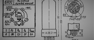
Gifts to everyone. Once upon a time I heard that in one of the two types of boxes you can exceed the speed, and specifically, if you listen to a track in a bump “out of tune.”
So, conditionally, we have HF and FI at 35 Hz. Each one has absolutely the same din, function and nutrition.
For example, a 29 Hz track is playing. On which box does the risk increase that the stroke will be exceeded and the reel will spit out? And why?
Comments 20
Expo box and don’t worry =) ChV kills din only because of the empty head of the owner of the ChV.
Expo somehow also lays down the din at once. If the settings are not correct, the din will die in ZYa. Either from the clip or from something extra.
The CV will hammer on the speaker until it falls apart and there are no sounds of any kind, and the FI will begin to wheeze.
slot, pipe, doesn't it matter?
Depending on the type of gap, preference is for a pipe with a double opening, but some slotted FIs are ironed like that =)
slot, pipe, doesn't it matter?
Idk. I had a closed box, now it is. I put two dins in the middle and didn’t notice. When closed, when you put too much on it, it started wheezing and I turned it down. And the chw beats to the last-))
It all depends on what kind of speaker you are going to use. For HF, you need a speaker with a lower quality factor and an increased stroke of the diffuser; the speaker must have protection against coil deformation in the form of a restrictive ring on the coil; if you overdo it with power, you will hear the characteristic knock of that ring and reduce the volume. The suspension should also be lighter. And in FI you can use any good din. I have two subwoofers with Magnat Classic 316 LF heads, only 16.5 cm in diameter, 80 W per head. They are in FI boxes with a setting of 36.7Hz, they play normally from 32-33Hz. They don't burn, they don't tear. I've been using them for three years now.
I have a budget Ural AS-D12.3TD4, it has xmax 29 mm, plays into 2 ohms, Monique weak swat 1.500.
This din, as a gift, still lives in my HF 36Hz, it has never been put in phi yet, today I want to put it in a slot phi 33 Hz, so I’m asking if, by chance, it will be possible to pour 29 Hz into it, t .To. In HF 29Hz it was not scary to turn it on, if not at full strength.
What is the natural resonance frequency of the dyne?
the manufacturer says 28 Hz
Yes, even if 30Hz, then 29Hz will be output without consequences, but why then make the box at 33Hz if Fs is 29? Do 30Hz and you will be happy
the manufacturer says 28 Hz
For me, Alphard will be more reliable
well, this is a gift horse, as they say)) And I’m taking the box for inspection, in the future I want to cut a new one. I don’t want to go below 33 for now, because... There’s already a lot of wind there, and there are plans to change from a hatch to a sedan. In general, I'm still looking for the right information)
“It’s also a resonator - an organ pipe, it’s also a transmission line”
DIY subwoofer for home - detailed instructions
Do-it-yourself subwoofer for the home —more precisely, for a home theater.
And although I don’t have much experience in making such structures, I nevertheless decided to take on assembling it. Moreover, I have long planned to purchase such a thing in order to enjoy the sound stage while watching movies. To begin with, I found out what power would suit me most - I decided that, given the area of the room, 100 W of power would be enough for me.
Then I began to look for suitable drawings and the necessary dynamic low-frequency emitter that suited me in all respects.
In the meantime, while the emitter and bass reflex were on their way to me via postal services, I began to prepare all the materials necessary for making the subwoofer.
Start of assembly
I bought this slab, 30mm thick, at a hardware store. By the way, in the same store, they cut it to size for me for a small fee. The drawings I had suggested using 19mm thick MDF, so I had to slightly adjust the dimensions to preserve the original internal volume of the box.
At this stage, we fix the structure with several self-tapping screws to determine any inaccuracies after sawing, but everything went fine, the workpieces correspond to the specified dimensions
Now you need to mark the points for milling the mounting locations for the speaker and bass reflex
Milling
We are preparing a manual router, and these are the cutters that I have in stock. All operations are carried out purely in a home workshop
- To perform high-quality milling, as you know, you need a compass, which was not at hand, so I made it myself from available materials
- As a result, this design was formed. It is with the help of this compass device that I can cut out a circle with a diameter of 55 mm or more
- When milling, be sure to connect a vacuum cleaner
- This is what happened at this stage
Speaker adjustment
- Just at this moment I received the speaker and bass reflex, and did a fitting
- Milling work for terminal installation
- Tried it on again
- After that, I made a chamfer around the entire perimeter so that there were no sharp corners.
- At this step, I placed all the sides of the body on polyester resin, which is somewhat similar to epoxy, but dries in half an hour, and then secured it with long self-tapping screws.
Putty and primer
After that, I started puttingtying the box; of course, it would have been possible to cover only the places where the screws were unscrewed, but I thought that it would look better when the entire body was treated with putty.
Therefore, I went over all the sidewalls with a large spatula, and in the end all the planes became ideal. After drying, I treated it with sandpaper, and additionally went over the plastic with an even finer composition of putty.
When it was all dry, I sanded it again. After sanding the putty layer, you can use developing powder to reveal any flaws.
The time comes for priming, followed by drying for at least a day, then sanding again with fine sandpaper.
After that, I applied a layer of metallic to the body and dried everything again; when it was dry, I covered it with car varnish. The end result is such a gorgeous body!
- Here are a couple more angles of the case
- It's very close here
- Tried the speaker in the hole, everything is perfect
Hull damping
- This stage consists of treating the inside of the box with anti-resonance material, like the one in the picture.
It is based on foil treated with a bitumen component - To create high-quality acoustic damping, I glued these layers inside the box - very dense
- Here is the sub after damping
- We mount all the components on the body
Next, it was necessary to decide what spikes needed to be installed.
However, it is not very convenient to move the subwoofer with such supports, as the floor covering can be damaged. I found a solution on my own - I bought this metal set in a furniture showroom, most likely these are handles for something
Looks pretty good!
Generally speaking, I have almost finished making the subwoofer enclosure. Now it's time to start installing a power amplifier. At first I wanted to make the subwoofer active, that is, to arrange all the components inside the box, but then I didn’t like this idea. Therefore, I decided that the amplifier for it would be a separate unit
Amplifier assembly
- Because I have experience in assembling amplifiers, I decided to assemble an antenna on the TDA7294, connecting them via a bridge circuit. But then I took a closer look at the characteristics of this microcircuit and read reviews about an amplifier assembled on such chips and discovered that the amplifier is designed to work only with an eight-ohm load
- Then I started looking for a more suitable circuit using bipolar transistors - I chose the Lanzar amplifier with an output power of 200 W at a 4 Ohm load, but you can get more. The circuit diagram is shown below
- For those who intend to replicate this amplifier, you first need to prepare the printed circuit board using the LUT method (laser ironing technology). It didn’t turn out a bit as we would have liked, but all the flaws can be corrected with varnish
- Maintaining the paths
- We install all the components on the board, here you need to be especially careful so as not to make mistakes
Bass reflex
Considering that the subwoofer operates at low frequencies, it is imperative to install a low-pass filter (LPF).
If the sound card has an output connector for connecting a subwoofer, then the low-pass filter does not need to be installed. But using the filter circuit below, I assembled it using operational amplifiers.
This circuit provides a sound volume control, a cutoff control, and there is also the possibility of smooth phase adjustment
Beyma presents three new LEX subwoofers
- Low-pass filter circuit board
- LPF assembled
- For the filter to operate correctly, it requires a stabilized supply voltage, so we assemble the stabilizer according to the diagram below
- Voltage stabilizer assembled
Amplifier test
At this stage, we test the operation and set the quiescent current of the output stage on the amplifier. Lanzar works great, good sound
Checking the low-pass filter showed that everything is functioning normally
At first I tested the amplifier on a weak TP-100 transformer I had with a secondary winding voltage of 20v, but this is clearly not enough for Lanzar.
Therefore, I had to look for a more powerful power source. A TV technician I know just happened to have one like this - TS-180, from an old tube TV.
All I had to do was remove the old secondary winding and wind my own, based on an alternating voltage of 27v
Did everything without any problems
Amplifier housing
- Now it’s time to make the case for the amplifier; I made the chassis from small aluminum corners
- I figured out how the radiator would turn out
- We will cover the frame with plywood, since I used all the scarce aluminum to make the previous amplifier,
- We process the ends of the plywood with a milling cutter
- Rear view
- Then everything is done according to the familiar technology - putty, sanding with sandpaper, primer, in general, everything is the same as with the main box. And at the end we varnish the body
- The final result is shown here
- View from a different angle
- Let's see what this complex will look like from the outside - in my opinion, it’s very good!
Installation of amplifier parts
- We mount everything in the amplifier housing and securely fix it
- On the low-pass filter, I slightly adjusted the controls, that is, I increased the distance between them, otherwise they were too close relative to each other
- We attach polyurethane support legs to the bottom of the amplifier housing
- I forgot to explain that during the installation process, I installed the speaker protection module and placed the indicator LEDs on the front panel. The red LED starts to light when DC voltage appears in the load, the green LED lights up for three seconds, this is due to the amplifier’s smooth switching system
Conclusion
To summarize, we can state that the power of the subwoofer for a home theater is quite enough, even too much! Excellent bass, you can feel the distinct assertiveness and elasticity of the sound. There is absolutely no wheezing, and other distortions are not even close.
The process of making a subwoofer with your own hands
Source: https://usilitelstabo.ru/sabvufer-svoimi-rukami-dlya-doma.html
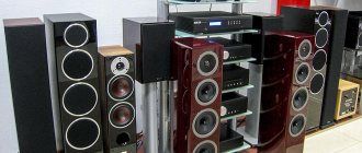
Acoustics design
Initially, select the number of columns, type, location. Obviously, producing more channels than a home theater has is an unwise tactical move. A cassette recorder will only need two speakers. At least six buildings will be released for the home theater (there will be more speakers). According to the needs, accessories are built into the furniture, the quality of low frequency reproduction is poor. Now the question of choosing speakers: in the publication by Naidenko and Karpov the nomenclature is given:
Three-way speaker system
- Low frequencies - CA21RE (H397) head with an 8-inch fit.
- Mid range - MP14RCY/P (H522) 5" head.
- High frequencies – head 27TDC (H1149) by 27 mm.
They presented the basic principles of designing acoustic systems, proposed an electrical circuit of a filter that cuts the flow into two parts (a list of three subranges is given above), and gave the name of purchased speakers that solve the problem of creating two stereo speakers. We avoid repetition; readers can take the trouble to look through the section and find specific titles.
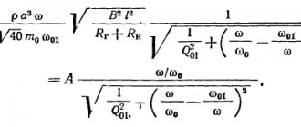
The next question will be the filter. We believe that National Semiconductor will not be offended if we screenshot the drawing of the Ridico translation amplifier. The figure shows an active filter with a power supply of +15, -15 volts, 5 identical microcircuits (operational amplifiers), the cutoff frequency of the subbands is calculated by the formula shown in the image (duplicated in text):
f = 1/2P RC;
P – number Pi, known to schoolchildren (3.14); R, C – resistor and capacitance values. In the figure, R = 24 kOhm, C is silent.
Active filter powered by electric current
Taking into account the capabilities of the selected speakers, the reader will be able to select a parameter. The characteristics of the speaker's playback band are taken, the overlap junction between them is found, and the cutoff frequency is placed there. Thanks to the formula, we calculate the value of the capacitance. Avoid touching the resistance value, reason: it can (disputed fact) set the operating point of the amplifier, the transmission coefficient. On the frequency response given in the translation, which we omit, the limit is 1 kHz. Let's calculate the capacity of the specified case:
C = 1/2P Rf = 1/2 x 3.14 x 24000 x 1000 = 6.6 pF.
It’s not that big of a capacitance; it’s selected based on the maximum permissible voltage. In a circuit with sources of +15 and -15 V, it is unlikely that the nominal value exceeds the total level (30 volts), take a breakdown voltage (the reference book will help) of at least 50 volts. Do not try to install DC electrolytic capacitors; the circuit has a chance of blowing up. There is no point in looking for the original circuit diagram of the LM833 chip due to Sisyphean labor. Some readers will find a replacement chip that is different... we hope for your understanding.
Regarding the relatively small capacitance of the capacitors (retail and total), the description of the filter says: due to the low impedance of the heads without active components, the ratings would have to be increased. Naturally causing the appearance of distortions due to the presence of electrolytic capacitors and coils with a ferromagnetic core. Feel free to move the range division boundary, the total throughput remains the same.
Passive speaker filters
Passive filters will be assembled with your own hands by anyone trained in soldering in a school physics course. As a last resort, enlist the help of Gonorovsky; there is no better description of the intricacies of the passage of signals through radio-electronic lines that have nonlinear properties. The presented material interested the authors in low and high frequency filters. Those wishing to divide the signal into three parts should read works that reveal the basis of bandpass filters. The maximum permissible (or breakdown) voltage will be scanty, the nominal value will become significant. Matching the mentioned electrolytic capacitors are capacitances with a nominal value of tens of microfarads (three orders of magnitude higher than those used by an active filter).
Beginners are concerned about the issue of obtaining a voltage of +15, -15 V to power speaker systems. Wind a transformer (an example was given, PC program Trans50Hz), equip it with a full-wave rectifier (diode bridge), filter, enjoy. Finally, buy an active or passive filter. This thing is called a crossover, carefully select the speakers, correlate the ranges more accurately with the filter parameters.
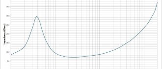
Technical characteristics and calculation of the size of the CV box
Loading…
An HF box or quarter-wave resonator is a hollow box made of any furniture material. The design is used for a subwoofer and allows for deeper sound with a harmonious spectrum. Such branded devices are quite expensive, but the box can be assembled independently from scrap materials. This is exactly what we will discuss in our review.
Purpose, design and principle of operation of the CV box
The design of the HF box is aimed at modulating the sound flow. The effect of sound transmission and reflection is used. Thanks to the special housing design, sound harmonization is achieved. This is especially noticeable at low frequencies and when installing a subwoofer. With the appropriate dimensions, the HF box will make the bass sound quite loud, bright, but unusually deep.
Subwoofer box
Purpose and use
In a certain context, this device can be compared to an analog-type sound processor. Now that the purpose is clear, let’s now look at the design, operating principle and calculations.
The proposed solution is especially in demand among motorists who want to install high-quality sound on used cars; with some effort, it will not be inferior to expensive audio systems.
So, in the technical understanding, the FM box, as implied by the name, is a resonator. We are talking about a hollow structure with the help of which sounds of a given frequency are reproduced. One of the functions of the resonator is to enhance audio sound.
Such a device in the car will allow you to listen to loud music, provide musical accompaniment in nature, or use it for commercial purposes, for example, for scoring weddings and celebrations.
The most popular solution is a box for a 12-inch speaker.
Operating principle
Motorists may be familiar with a resonator, another example of which is the CV box For example, it is used as a functional element of a muffler. In this case, the hollow structure has its own characteristics and another purpose.
From a technical point of view, a resonator is an oscillatory system that accumulates vibrations due to frequency resonance. Typically, the design involves “working” with a limited set of frequency characteristics. Depending on the design, resonators of cumulative and instantaneous action differ.
Homemade wooden box
The storage resonator accumulates external energy by reducing the frequency of internal oscillations. In a mathematical context, any resonator design whose oscillation frequency is greater than the oscillation frequency of the external influence is cumulative. This happens whether the diameter is 10 or 12 inches, but you need to choose a different volume.
Instantaneous action implies the correspondence of the internal oscillatory force in period to external oscillations. Such resonators increase the sound power due to thermal absorption of the surrounding space, shifting the frequency at the input power - changes due to an increase in the playback interval.
The common CV box has a rectangular shape with partitions resembling a caterpillar in arrangement. The appearance will depend on the speaker and its features, size – 10″ or 12 inches. At the moment, you can find drawing diagrams for any frequency device and make a resonator at no extra cost. It will differ slightly from the brand name.
Source: https://1avtozvuk.ru/subvufer/chv-korob
How to calculate a resonator for the Urals yourself?
First of all, we note that the main material for making this audio device is multi-layer moisture-resistant plywood. The speaker input is sized according to the selected model. The volume and design will depend on the technical tasks: interior features, required power and other features.
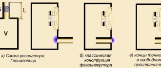
Designs depending on the direction of the port
The figure shows that the direction of the port and other parameters also influence the design. Sometimes drivers, after making calculations, are concerned that the dimensions are very large compared to the available space in the cabin, so they recommend a design that is suitable for this task.
Other housing options
The photo shows an example of the calculation of the HF box, but in total the cross-sectional area of the tunnel is taken into account (for example, 10″ or 12″), depending on the caliber of the subwoofer, for example, Machete m10d2.
Example
Use the Quarter Wave Box calculation program. You will only need to enter the speaker parameters and box volume. Otherwise you will have to make the drawings yourself.
To do this, use ready-made recommendations - a table with subwoofer sizes for 10, 12 inches and others. The cells show the volume that needs to be taken as a basis to achieve certain audio parameters. A “tuning” is also selected depending on the machine owner’s preferences and frequency. The box can be designed for two or more speakers, they can be different 10″ or 15″.
The proposed variations demonstrate some solutions for organizing a car interior media system that are available for self-production. With a little effort, you will get a high-quality sound system in your car for your new Machete m10d2 or Ural, taking into account the features of your interior and preferences.
Subwoofer drawings for 15 heads. DIY subwoofer using HF technology
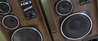
The subwoofer speaker is the main component in building powerful and high-quality bass. But the box where you place it plays an equally important role. Depending on the design and type of box, the same subwoofer speaker can be made to play differently. For example, make the bass softer or harder, faster or louder.
And if the box is designed incorrectly, you will be completely disappointed in the purchased subwoofer. In this section of our information portal you will find: various drawings of boxes for popular subwoofer speakers designed and tested by professionals. You can choose the box setting that best suits your musical taste. Ready-made detailing with dimensions of parts. i.e.
you can give the drawing to a company that provides wood cutting services (furniture), and after a certain time pick up the finished parts. Or you can save money and make the cut yourself. In any case, everything is routine work; what displacement of the box is needed, what the length or volume of the port should be, and much, much more we took upon ourselves.
All you have to do is download the calculation of the box for the subwoofer, saw it, twist it, tighten it if desired, and enjoy the loud and high-quality bass.
I offer all lovers of good, solid bass a closed-type subwoofer design.
Nowadays, all audiophiles lack conventional stereo sound; they want at least a 2.1 system. And for such a system, in addition to the left and right speakers, a third one is needed - a subwoofer.
Normally, the design of a subwoofer should begin with the selection of a low-frequency speaker (size, power), then having the parameters of the speaker and using one of a number of well-known programs for calculating subwoofers, obtain a drawing of the box.
I had a low-frequency head, 8 inches in size. According to the design, the execution decision was made - BaundPass 6th order. This design has the highest efficiency in terms of low-frequency sound, plus the speaker is completely protected from external mechanical damage.
I took a risk, took as a basis the drawing of the box from a 10-inch speaker and proportionally reduced it to fit my 8 inches. In parallel, I drew everything in SPlan 7.0, with all dimensions.
The material for making the subwoofer housing is better to use MDF or chipboard, at least 16-18mm. I was lucky, I had an old, two-bedroom desk. Material thickness – 17mm. If someone repeats the design, then take into account your material thickness in the drawing.
- To make it, I needed the following tools:
- An electric jigsaw and files for it for a clean cut; - A hand-held electric router and a set of cutters; - An electric drill, a screwdriver, wood drills; - Files, sanding paper; - A scriber or marker for discs (thin); - – The clamps are wide;
Source: https://gksteel.ru/measurement-and-calculation/subwoofer-drawings-for-15-heads-subwoofer-on-technology.html
DIY subwoofer. Several options for self-production
It may seem strange, but the speaker is mainly characterized by three parameters proposed by Till and Small:
| Fs is the resonance frequency in open space; |
| Qts - total quality factor of the speaker; |
| Vas is the equivalent volume. |
Fs
- this is the resonance frequency of the speaker without any acoustic design. This is how it is measured - the speaker is suspended in the air at the greatest possible distance from surrounding objects, so that now its resonance will depend only on its own characteristics - the mass of the moving system and the stiffness of the suspension.
Qts
- the ratio of the transfer function of the speaker at frequency Fs to the transfer function at frequencies where the amplitude-frequency response (AFC) of the speaker is horizontal, i.e. at frequencies above Fs. In other words, Qts characterizes the efficiency of the speaker at the resonant frequency.
Vas
- the volume of air that is flexible (the inverse of elasticity) is the same as the moving speaker system.
When a speaker is placed in a closed box (CC), the flexibility of the air inside the box adds to the flexibility of the speaker's moving system and its resonant frequency changes.
There is the following pattern: when a speaker is placed in a box of volume Vas, its resonant frequency Fs and quality factor Qts increase by 1.4 times.
Measuring these parameters at the first glance at the design is quite a hassle, but having done it once, all doubts disappear - everything turns out to be quite simple.
First you need to prepare:
| download signal generator program for sound card Marchand Function Generator |
| You can also merge Oscilloscope 2.51 - an oscilloscope to the sound card. By connecting the output to the input, you can see what the generator is doing |