Amplifier circuits for TDA2005
The TDA2005 microcircuit belongs to the category of inexpensive and widely available integrated UMZCH . A relatively small number of attachments, combined with quite good electrical characteristics, the presence of output overload protection, thermal protection, as well as the ability to set the transmission coefficient within a wide range (by selecting resistor resistances in the OOS circuit). to build a wide variety of amplifiers based on the TDA2005 stereo, bridged, multi-band , etc. This article provides three circuits using these chips. 1. Stereo amplifier on TDA2005. Figure 1 shows a circuit of a simple full stereo amplifier with the following parameters: 1. Output power at THD = 10%. At a load of 2 ohms...2 x 10W. 2. Output power at THD = 0.3%, at a load of 2 Ohms ... 2 x 6 W. 3. Input signal level, to obtain a power of 1 W ... 90 mV. 4. Gain factor taking into account losses in the tone control... 36 dB. 5. Possibility of increasing the gain up to ... 50 dB.
The amplifier is designed to work as part of a homemade music center; it can be used to voice signals from an audio player, computer or other sound source. The stereo input signal goes to connector X1. On variable resistors R3. R5, R9 made a passive adjustment block. Double resistor R3 adjusts the HF tone simultaneously in both channels. Double resistor R5 is used to adjust the volume. Resistor R5 is used with a tap from the “horseshoe”, which serves for loudness compensation, which improves the sound when operating at low volumes. Single variable resistor R9 serves as a stereo balance regulator. The amplifiers included in the TDA2005 are powerful operational amplifiers with single-polar power supply, direct inputs are pins 5 and 1, inverse inputs, respectively, are pins 4 and 2.
By changing the resistance of resistors R13 and R15 (or R12 and R14), you can change the transmission coefficient of the amplification channels over a wide range. For resistances R13 and R15 the dependence is inverse, and for R12 and R14 it is direct. Circuit R10-C12 serves to smoothly turn on amplifiers, avoiding current surges in speaker systems. Capacitors C13 and C16 create a voltage boost to the output stage, increasing the output power without increasing the supply voltage. The amplifier can operate without them, in this case C13 and C16 are removed, and pins 7 and 11 are connected to the positive power bus (pin 9). But in this case the maximum power is lower. The parts of the adjustment unit are mounted directly on the terminals of variable resistors installed on the front panel of the amplifier housing. Since the regulators are passive, it is more convenient in all respects.
The parts of the amplifier itself are mounted on a small printed circuit board ( Fig. 2 ) made of single-sided foil fiberglass. Manufacturing technology – any. Output capacitors C21 and C18, as well as smoothing capacitor C19, located outside the printed circuit board (rigidly secured with clamps in the amplifier housing). The printed circuit board is attached to the heatsink by means of the heatsink plate of the microcircuit with one screw. To remove heat from the microcircuit, a radiator is used, the design of which is shown in Fig. 3 . The radiator is made of an aluminum profile, which is used to construct suspended ceilings or frame plasterboard panels. For one radiator, you need to cut two pieces 10-15 cm long. Then one of the pieces needs to be cut lengthwise into two identical parts (two corners). Then the two corners are folded “over the roof” and placed in the middle inside a whole piece of profile. All mating surfaces must be coated with heat-conducting paste. A hole is drilled in the middle of the structure, into which the microcircuit is attached using a screw and nut. This mount also serves as a mount for the plates of such a radiator. Power transformer T1 with a power of 40W, you can use a ready-made one, type TBS 004 220/12. The secondary winding voltage is 12 volts. If you don’t have a ready-made one, you can use any suitable network voltage with a voltage on the secondary winding of 12 -14 volts and a power of at least 40W. The setup consists of setting the required sensitivity of each channel by selecting resistances R3, R15 or R12, R14. This amplifier can be used with any suitable analog low-frequency signal source. 2. Bridge amplifier 20W on TDA2005. Based on the TDA2005 chip, you can make a multi-channel amplifier for, for example, a car speaker system, with which you can reproduce a signal from an MP3 player or other source. The range of application of the amplifier is wide.
Figure 4 shows a diagram of an amplifier module on a TDA2005 chip , the amplifiers of which are connected in a bridge circuit, having the following parameters: 1. Supply voltage ... 5-18V. 2. Rated supply voltage… 14.4V. 3. Output power at THD = 10% at a load of 4 Ohms ... 20W. 4. Output power at THD = 10% at a load of 3.2 Ohms ... 22W. 5. Output power at THD<1% at a load of 4 Ohms... 15W/ 6. Amplifier sensitivity... 220mV. 7. Frequency range…20-20000 Hz. 8. SOI at power up to 8W... <0.3%. The first amplifier (input – pin 5) is connected as usual, in a stereo amplifier circuit, the direct input of the second amplifier (pin 1) is shunted by AC by capacitor C3. The signal is supplied to the inverse input of the second amplifier (pin 2) from the output of the first amplifier through the divider R5-R4-R3, formed by resistors that set the feedback. In order to obtain equality (modulo) of the signals at the outputs of the amplifiers, the resistance of the OOS R6 of the second amplifier is twice as large as the similar resistance (R3) of the first amplifier. An acoustic system (with a resistance of at least 3.2 Ohms) is connected between the outputs of these amplifiers.
The bridge circuit allows you to obtain double power amplification and allows you to get rid of the bulky high-capacity coupling capacitor, which is usually placed between the amplifier output and the speaker system. The absence of this capacitor also improves the performance of the amplifier at low frequencies.
The amplifier module is assembled on a printed circuit board, the diagram of which is shown in the figure. It is optimal to use a system of four such amplifiers in a passenger car, turning them on according to the diagram in Fig. 5 . Using variable resistors, you can optimally adjust the levels of signals received by the modules, so that there is an optimal ratio of the powers of the stereo channels, as well as the front and rear channels.
All four amplifiers can be placed on a common radiator and in a common housing. Printed circuit boards do not have their own fastening elements; the role of the fastening element is performed by the radiator plates. 3. Two-way amplifier on TDA2005 . Using two TDA2005 microcircuits, you can make a two-way amplifier, in which each of the stereo channels will contain a two-way amplifier with a crossover frequency, for example, 2 kHz. One of the TDA2005 amplifiers will operate in the low-frequency channel (20-2000 Hz) and from its output the signal will go to the low-frequency speaker system. The second amplifier TDA2005 will operate at frequencies from 2000 Hz to 20000 Hz and from its output the signal will be sent to the HF acoustic system .
A schematic diagram of one of these channels is shown in Fig. 6 . The input signal is fed to two passive filters - a low-pass filter on elements R1-C1 and a high-pass filter on elements C3-R2. The level of the low-frequency signal is not adjustable; an acoustic system operating at low frequencies (or a low-frequency speaker of the acoustic system) is connected to the output of the top amplifier in the circuit. To improve the reproduction of low-frequency components, the capacitance of the separating capacitor C10 was chosen to be large (a capacitor K50-35 with a capacity of 4700 μF for a voltage of 16 volts is used). Accordingly, higher capacitances of capacitors C2, C7 and C8 than similar capacitors of the high-frequency channel.
The level of the high-frequency channel is regulated using a variable (or tuning) resistor R2. With its help, you can match the levels of the high-frequency and low-frequency components, respectively, the output of the speakers and obtain equality or the necessary predominance of low frequencies or high frequencies. In the high-frequency channel, electrolytic capacitors of smaller capacity are used, in particular, the capacity of the transition capacitor C13, through which the signal is supplied to the speaker system, is only 100 μF. The parts of both stereo channels are mounted on printed circuit boards similar to the stereo amplifier board Fig. 2 , only here two boards are needed. Input circuits with tone, balance and volume controls can be made as in the stereo amplifier in Fig. 1 . But the power source must be twice as powerful, since the current consumption by the two-way stereo amplifier circuit is twice as high. This also applies to the radiator - it should be twice the size of the stereo amplifier radiator ( Fig. 3 ). The efficiency of the amplifiers of the TDA2005 chip is about 60%, which means that the power of the power transformer must be at least 1.8 times the total maximum power of the amplifiers. Speaker systems can have impedance from 2 to 8 ohms. For bridge amplifiers, the AC resistance should be no lower than 3.2 Ohms ( Fig. 4 ), and for stereo amplifier circuits ( Fig. 1 ), the AC resistance should be no lower than 1.8 Ohms.
source: “RADIO CONSTRUCTOR”, 11 – 2005, pp. 17-20
Similar
A simple 20 W mono amplifier (or 10 W stereo) assembled on the TDA2005 chip does not require adjustment. It only requires a little time to assemble and mount it into the case if desired.
The amplifier specifications for the TDA2005 are as follows:
- Supply voltage (V) - 6-18
- Peak output current (A) - 3
- Quiescent current (mA) - 75
- Reproducible frequency range (Hz) - 40-20000
- Total harmonic distortion (%) - 1
- Nominal load resistance (Ohm) - 3.2
- Minimum load resistance (Ohm) - 2
- Output power (W at supply voltage 18 V) - 22
- Input sensitivity (mV) - 300
- Gain (dB) - 50
In this article I will offer you three board options for a mono amplifier and one option for a stereo amplifier.
Or order a “bought and connected” set on the Internet.
This amplifier has proven itself to be simple, reliable and unpretentious. It is most often built into homemade home guitar cabinets (i.e., suitable for guitarists), as well as in low-power car radios (especially in the 90s). Don't let the phrase "low power" scare you - the gain of this chip is enough to scare the neighbors. It’s just that 20 W for a car now is really nothing compared to kilowatt amplifiers and speakers, which can easily burst your eardrums when turned on at full power.
Let's start with the board, which, in my opinion, has the most successful ground layout.
Here is the diagram, board, arrangement of parts on the board and parameters of the amplifier parts on the TDA2005:
Simple mono amplifier board based on TDA2005
Layout of parts for a simple mono amplifier on TDA2005
Parts List:
It was the version with this board that I built into my conversion of the Soviet S30 speaker into a guitar combo amplifier.
There is no need to mirror the board.
After assembly it turned out like this:
Only in the photo there is a very small radiator. For an amplifier on TDA2005 you need more. Therefore, it was replaced with a larger radiator.
Now let's move on to the rest of the PCB layout options.
The second version of the mono amplifier board on TDA2005.
How to solder the volume control and signal wires:
The third version of the mono amplifier board on TDA2005.
Choose any option. I liked the first one better.
Now to the stereo amplifier on the TDA2005.
His fee is a little more:
And the scheme is a little different:
Let me remind you that the stereo amplifier on the TDA2005 develops half the power of a mono amplifier. However, you can always assemble two mono amplifier boards and get stereo. Only power is needed with the same voltage, but a current of about 5-6 A.
It remains to show one more version of the mono amplifier circuit recommended by the manufacturer:
Project Black Angel-2
Preface
Before I start my article, I want to say that if you have strong nerves, a lot of free time, certain skills in electronics, like to listen to very loud music in the car, powerful bass and are willing to spend a lot of money on such a project, then this article is just for you !
I guess I'll start with thanks. Many thanks to the administration of this wonderful site, the moderator of the audio forum zuboka and everyone who helped with the power amplifier. The idea of creating a high-power amplifier has been around for a long time, but due to lack of time and finances, the project was postponed. And then summer... vacation... It was decided to turn the idea into reality and exactly 3 months were spent for this, since there were big problems with the parts, but despite this, the amplifier complex was successfully assembled and tested. To begin with, I would like to clarify the meaning of the expression “enhancing complex”. The fact is that it was decided to assemble a high-quality amplifier that could power the entire car audio system. The entire power section (power amplifiers) had to be combined “under one roof”, the result was 5 separate amplifiers with a total power of 680 watts, do not confuse with Chinese watts, there is a pure 680 watts of rated power, the maximum power of the system reaches 750 watts. The requirements for the complex were as follows. 1) High sound quality 2) High output power 3) Relatively simple design 4) Low cost compared to the prices of factory systems of this kind 5) Ability to power 10 -12 speakers + subwoofer To implement this idea, 5 separate power amplifiers were used, including a high-quality amplifier based on the Lanzar circuit to power the subwoofer channel.
Below are the parameters and series of microcircuits that were used in this amplifier. TDA 7384 - 4x40W (2 pieces, total power of microcircuits 320 watts or 8 channels, 40 watts per channel) TDA 2005 - 1x20W (2x10W) (2 pieces, total power of 40 watts or 2 channels of 20 watts each) The above microcircuits are designed to power the front acoustics. This solution is the most economical; to create an amplifier of this kind, you can find out about the monetary costs at the end of the article. The most difficult part in any amplifier of this kind is the voltage converter, it is designed to power the subwoofer amplifier, perhaps we’ll start with it.
Voltage transformer
It took me exactly two weeks to create.
The voltage converter pulse generator (from now on PN) is built on a traditional TL494 microcircuit. This is a high-precision push-pull PWM controller, a domestic analogue of 1114EU3/4. The microcircuit does not contain an additional output amplifier. The additional cascade is built on low-power transistors, the signal from them is supplied to the gates of the field switches.
The circuit is known as a push-pull or push-pull converter. The circuit is not new, but I had to change some of the circuit values to suit my needs. On each shoulder there are two powerful field workers of the IRF3205 series. Through heat-conducting gaskets they are mounted on heat sinks that were removed from computer power supplies
In the rectifier part, KD213A diodes are used, they are just for such purposes, since they can operate at frequencies of 70-100 kHz, and the maximum current reaches 10 amperes; in this circuit, the diodes do not need additional heat sinks, I did not notice any overheating.
I used 2 relays for power supply, 20 amperes each, but it is advisable to install a relay for 50-60 amperes, since the converter draws a considerable current. The remote control system (REM) is implemented in the PN, i.e. No powerful switches are needed to turn on the subwoofer. By applying plus to the remote control, the relays are instantly activated and power is supplied to the converter.
I especially struggled with winding the transformer, since the transformer was of my own design. Unfortunately, I could not find ferrite rings, so I had to go for an alternative solution. We got several computer power supplies for free, and large transformers were soldered out of them.
The ferrite halves are tightly glued to each other, so they need to be heated with a lighter for 30 seconds, then carefully removed from the frame. As a result, the standard windings were unwound from the transformers, and the terminals were cleaned.
Next, the side wall of each frame was cut off.
At the end the frames are attached to each other. The result is one elongated frame onto which we can freely wind the windings we need
Through experiments, the required number of turns in the primary winding was found. As a result, the primary winding contains 10 turns (2x5vit) with a tap from the middle. Winding was done immediately with 5 strands of 0.8 mm wire. First, 5 turns are wound along the entire length of the frame, then we insulate the winding and wind another 5 turns on top identical to the first. We wind the windings IN THE SAME DIRECTION, for example clockwise.
After winding the wires, we twist them into a pigtail, not forgetting to remove the varnish in advance, then we tin them and cover them with a layer of tin. Now you need to phase the windings. In fact, there is nothing difficult here, you just need to find the “beginning” and “end” of the windings and connect, for example, the beginning of the first winding with the end of the second or the beginning of the second with the end of the first, the connection point is a tap to which the plus from the general power supply is supplied ( see diagram). After phasing the windings, we wind a test secondary winding; it is needed so that if the phasing is incorrect, we do not wind the entire secondary winding. The test winding can contain any number of turns, for example 3 turns with 0.8 mm wire, then we assemble the transformer by inserting the core halves.
When turning on the circuit, the transformer should not emit a “buzz”; the transistors should not overheat if the converter is idle. We connect a 12-volt incandescent lamp of a couple of watts to the secondary winding, which should light up with almost full heat, while the transistors should be cold and only after a few minutes of operation you can feel a slight heat release. If everything is normal, then remove the test winding and wind in its place a normal one, which is wound according to the same principle as the primary.
This time the winding is wound with two strands of 0.8-1mm wire and contains 30 turns (2x15 vit). Two identical windings are wound, each with 15 turns and stretched along the length of the entire frame. After winding the first half, we insulate the winding and wind the second one on top. The windings are phased according to the same principle as the primary.
After winding the secondary winding, the wires at the ends are twisted and tinned. At the final stage, the core halves are strengthened. The transformer is ready!
IMPORTANT! In converters of this kind (push-pull) there should be no gap between the halves of the core! Even the slightest gap of a fraction of a millimeter will lead to a sharp increase in the quiescent current and overheating of the field-effect transistors! It was because of my clumsiness that I burned several field-effect transistors. Make sure that the ferrite halves are pressed against each other as tightly as possible. Such a transformer is capable of providing the required voltage and current to power the subwoofer amplifier. We solder the transformer onto the board and begin winding the chokes.
Chokes The circuit uses 3 chokes. They are designed to filter out RF noise and interference that can form on the power lines. The main choke is used on the positive power line of the converter. It is wound with 4 strands of 0.8 mm wire. The ring used those in computer power supplies. The number of throttle turns is 13.
The remaining two chokes are located after the diode rectifier in the PN, they are also wound on rings from computer power supplies and contain 8 turns of 3 cores of 0.8 mm wire.
To be honest, I didn’t expect that such a high-quality voltage supply would be obtained, the quiescent current of the circuit does not exceed 200 mA, this is normal for such a monster, the output voltage is +/-63 volts, the slope is insignificant, only half a volt. The maximum power of the converter would allow powering two of these amplifier, but here it works with a large margin.
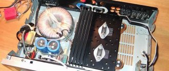
Amplifiers based on TDA2005, for low-power heads
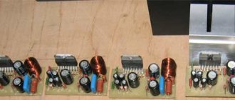
Assembling this block took only 2 hours. During this time, two identical power amplifiers were assembled. The amplifiers were chosen as the cheapest option for low-power speakers; they can be used to power speakers located on the front panel of the car. Each chip develops 20-24 watts of power and has very good sound quality
Each microcircuit is connected via a bridge circuit; with a stereo connection, one microcircuit is capable of delivering up to 12 watts into a 4 ohm load
The microcircuits are installed on the heat sink through an insulating gasket. The volume is adjusted in advance using a regulator. At first, another board was planned, amplifiers were assembled from this one, then a general board was invented, which was entered into the project archive.
TDA 7384 for front speakers
For more powerful speakers, TDA 7384 quadraphonic microcircuits are used. Each microcircuit is capable of delivering up to 40 watts of power per channel into a 4 Ohm load. The result is 8 channels of 40 watts, sounds very good.
Such microcircuits are used in car radios; if you are too lazy to buy them, you can get them from non-working radios. The connection diagrams are quite simple. The chips have MUTE functions (mute mode). If, through a 10 kilo-ohm resistor, this pin is connected to the power supply positive, then the sound on all channels will turn off, therefore, we leave this pin free. ST-BY system (sleep mode), we connect this pin through 10k to the power supply positive; when turned off, the microcircuit will be in “sleep” mode. Input capacitors to taste, capacity from 0.1 to 0.47 μF, it is advisable to use film capacitors.
Microcircuits have different filters independent of each other; if you use a common filter, then noise and excitation are possible. Both amplifiers start working when +12 volts are supplied from the battery to the REM pin. The amplifiers were assembled on one board, but later the blocks had to be rearranged, so each amplifier was implemented on a separate board.
Subwoofer amplifier
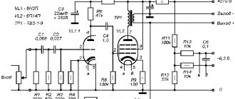
The famous Lanzar circuit, full description, assembly, circuit and configuration are described here, so there is no need to talk about this amplifier. The amplifier is completely assembled using transistors, has very good sound quality and increased output power. I made some changes in the diagram and below is the diagram I used to assemble it, the original diagram in the same forum thread.
Since I could not find some of the circuit ratings, I had to make some changes, in particular the emitter resistors were replaced with 0.39 Ohm 5 watts. The BD139 transistor was replaced with a domestic analog KT815G, in addition, the low-power transistors of the differential stages and pre-output stages of the circuit were replaced.
Electrolytic capacitors can be removed at the input if the input is replaced with 2.2 µF or more. It is advisable to do the first start-up of the amplifier with one pair of output transistors with the input shorted to ground, so that in case of breakdowns the transistors of the final stage do not burn out; they are the most expensive thing in this amplifier.
Pay special attention to the installation of the circuit, monitor the pinouts of the transistors and the correct connection of the zener diodes, the latter, if connected incorrectly, work like a diode. I installed a regular quiescent current regulator, I do not advise anyone to repeat my mistake, it is better to install a multi-turn one, it can be used to accurately adjust the quiescent current of the circuit, also convenient for setup. Transistors of differential stages do not need additional cooling, but the output and pre-output stages require a heat sink.
The output stage of the amplifier operates in AB mode, this is essentially a fully symmetrical circuit, the level of nonlinear distortion is reduced to a minimum. Due to its high performance, this amplifier belongs to the Hi-Fi category; getting 300 watts from this amplifier is not a problem. It is also possible to connect a 2 Ohm load at the output, i.e. you can power as many as two subwoofer heads by connecting them in parallel. In this case, you cannot raise the amplifier voltage above 45-50 volts.
You can increase the power of the amplifier by adding one or two more pairs of output transistors, but do not forget about increasing the power supply, since the output power of the amplifier directly depends on the power supply.
AC protection
Despite the fact that the power amplifier is quite reliable, sometimes problems can occur. The output stage is the most vulnerable part of any amplifier; due to the failure of the output transistors, a constant voltage is formed at the output. The constant disables the expensive dynamic head. Any amplifier of this kind has protection that will protect the speakers from constant voltage. When the amplifier is turned on, the relay closes, including the head; with a constant voltage at the output of the PA, the relay opens, maintaining the head
The protection has a relatively simple circuit, contains 3 active components (transistors), a 10-20 ampere relay, and the rest is little things. When the PA is turned on, the relay closes with a slight delay. Power for protection is supplied from one arm of the converter, through a limiting resistor of 1 kOhm, select a resistor with a power of 1-2 watts.
Low-power transistors can be replaced with any others whose parameters are similar to those used. The relay is connected to the collector of a more powerful transistor, therefore, the final transistor needs a more powerful one. From the domestic interior, you can use transistors KT 815.817 or more powerful - KT805.819. I noticed heat generation on this transistor, so I mounted it on a small heat sink. Protection and output signal indicator are mounted on one board.
Stabilization block
Bipolar voltage stabilizer provides the necessary voltage to power the filter unit and audio signal indicator. Zener diodes stabilize voltage up to 15 volts.
This unit is assembled on a separate board; it is advisable to use zener diodes with a power of 0.5 watts
Audio level indicator
I won’t go into much detail about the operation of the circuit, since the circuit of such an indicator is described in one of my articles.
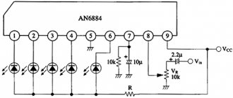
The indicator uses LM324 microcircuits. It is advisable to use an operational amplifier for these purposes, since the microcircuits cost only $0.7 (each). The indicator uses 8 LEDs; you can install any LEDs that are at hand. The indicator operates in the “column” mode. The indicator is powered by a voltage converter, then the voltage is stabilized to the desired value and supplied to the level indicator. The indicator is connected to the output of the power amplifier; using a trimmer, we adjust the indicator to the desired level of LED response.
Adder and low-pass filter block
The adder is designed to sum the signal of both channels, since we have only one subwoofer. After this, the signal is filtered, frequencies lower than 16Hz and higher than 300Hz are cut off. The control filter cuts the signal from 35Hz - 150Hz.
At the output there is a smooth phase control for best matching of the subwoofer with the car's acoustics. I used mostly film capacitors, although ceramic ones will work just fine.
Assembly
After a thorough check of all blocks, you can begin installation.
Unfortunately, I couldn’t find a case from a DVD player or anything else convenient. I attached indicator LEDs to the front panel, where the display used to be located. All boards are attached to the bottom of the amplifier through insulating washers, which in turn were removed from domestic equipment
All microcircuits and transistors are screwed to the heat sinks through insulating gaskets. It is advisable to use thermal paste; unfortunately, we do not sell it, but even without it everything is not so bad. The input connectors of the amplifiers were soldered out of the DVD, and a connector from a car radio was used as output terminals.
My design uses only one cooler, it is designed to cool the heat sinks of the PN and TDA7384 power switches; the subwoofer amplifier does not need forced cooling, since for it I selected a huge heat sink that practically does not heat up. The power wires of each amplifier are connected to common power terminals. REM control allows you to turn off any of the amplifiers (for example, a pair of TDA 2005) at the right time. Each amplifier is powered through relays, which are activated when positive is applied to the REM pin.
Each of the amplifiers has a separate remote control system, which is located on the contact platform on the side of the housing.
Subwoofer box
A couple of months after the start of assembly, I managed to buy a SONY XPLOD XS-GTX120L subwoofer head, the head parameters are below. Rated power - 300 W Peak power - 1000 W Frequency range 30 - 1000 Hz Sensitivity - 86 dB Output impedance - 4 Ohms Frequency range - 30 - 1000 Hz Diffuser material - polypropylene
Since stores only sold laminated chipboards, and we don’t have MDF at all, we had to choose from what was available. Fortunately, we were lucky with the material. Chipboard from USSR times was perfectly preserved in the attic, thickness 22 mm.
Next, the store purchased self-tapping screws with a length of 50mm (50 pcs.) and white silicone sealant (if available, buy transparent). The box was calculated using the WinISD program. Volume is about 83 liters.
The diameter of the FI port is 14 cm, the length of the pipe is 7 cm. A hole with a diameter of 28 cm was cut for the head. After making all the parts of the box, it was time to assemble it. It is convenient to start assembly by joining the bottom and front of the box. First, holes for the screws were made with a drill (with a small diameter drill), and only then the screws were screwed on. Before this, the fastening points were covered with PVA glue. There is no need to spare glue, so as not to complain about whistling later. I got a pretty good box, I worked as neatly as possible. Finally, the seams were coated with silicone on the inside of the box (silicone has an unpleasant odor, so this work should be done in a garage or outdoors). After assembling the box, I couldn’t resist, put the head where it was supposed to be and turned it on
I cannot convey this in words or even in a video, because it needs to be felt, not heard. You can feel the full volume of the box, the scope of the head, the power and quality of Lanzar, and all this is embodied in pressure on the chest…. It’s impossible to describe this in words, and only then do you begin to understand that everything around you is collapsing and falling apart, the glass is moving on the table by itself, the glass is beginning to “swell” from the pressure. In a word, everything in the house was under a “dose” of vibration.
Next, the box was covered with carpet. Carpet 120x200mm, enough for the entire box.
We sold special glue for carpet, but a can of aerosol costs $25, so we had to use PVA glue. To begin with, I sanded the box; this process took me 4 hours. Apply PVA glue to the already cut carpet. After this, the box needs to be “rolled” over a pre-cut carpet. We wrapped the box, now in order for the glue to dry properly, we hammer small nails along the edges, then after drying they can be removed or left.
Then we cut out the holes for the head and the bass reflex. The head is attached to the box with ten self-tapping screws, this ensures tight contact, no additional gaskets are needed.
The output contacts of the box are made from a connector for the network cable of a computer power supply unit; the manufacturing process is clear from the photographs.
This alternative solution is again caused by a shortage of factory connectors.
It turned out well. A separate hole was cut for it. On the inside, after sealing the wire, the connector hole was sealed with silicone sealant to avoid whistles and unwanted noise.
Total construction costs
Voltage converter :: BC557 3pcs - $2.5 TL494 1pc - $1 IRF3205 4pcs - $10 Diodes KD213A 4pcs - $4 Polar capacitors - $10 Non-polar capacitors - $3 Resistors - $2 Chokes and transformers - from old PC power supplies Relay - from a voltage stabilizer Lanzar amplifier: Transistors 2SA1943 2pcs - $6 2SC5200 2pcs - $6 2SB649 2pcs - $2 2SD669 2pcs - $2 2N5401 2pcs - $1 2N5551 2pcs - $1 Resistors 5 watt - 4 pcs - $3 Other resistors - 4$ Non-polar capacitors - 3$ Polar capacitors - 5$ Zener diodes - 2 pcs - 1$
Other amplifiers: TDA7388 2 pcs - $15 TDA2005 2 pcs - $2.5 Resistors - $2 Non-polar capacitors - $4 Non-polar capacitors - $6
block : TL072 1 piece - $1 TL084 1 piece - $1 Non-polar capacitors - $3 Resistors - $2 Regulators 3 pieces - $4
block : LM324 2pcs - $2 LEDs and everything else - $2
block : Transistors $2 Zener diodes 13 volt 6 pcs - $1.5 Stabilizers 7815 2 pcs - $1.5 Zener diodes 7915 1 pc - $0.7 The rest - $2
AC protection: Transistors - $2 Relays - everything else is free $1 Plugs, sockets and connectors were fortunately in stock
Subwoofer box: Self-tapping screws 50 pcs - $0.5 Sealant 2 bottles - $2 Chipboard - free PVA glue - free Head - $65 Carpet - $15 Of course, I won’t go into the price of each part, and gave approximate expenses. The total value of the parts taken together is indicated; in general, such an amplifier can be assembled for $170, but I spent much more due to the large shortage of parts.
Results
That's all. I'm pleased with the results, very pleased! It is not possible to buy such an amplifier; amplifiers of similar power cost from $400! Although Chinese manufacturers offer it for significantly little money, quality and reliability... In general, the amplifier turned out to be a thrice-bang success! Everything works great, all you have to do is buy a car and enjoy your hand-made amplifier, while the amplifier will work at home for now, from a powerful 12-volt power supply.
The entire system was created in conditions of a severe shortage of parts, it was necessary to run around workshops and find the necessary parts, some blocks (voltage converter, AC protection unit) were assembled on breadboards due to the lack of foil fiberglass and a laser printer, the only thing that was at hand , this is a piece of getinax on which lanzar was assembled. The board drawing was done entirely by hand, using a matte manicure, a ruler and solvent... there were no other options. In the end, in my opinion, it turned out to be a good board.
In the end, you can boast that you will be the only one with such an amplifier in your car, yet it is completely handmade.
Despite some difficulties, I tried to assemble the blocks as neat as possible, so all the breadboards were covered with green tape in advance for a beautiful appearance, and I leave it to your judge to judge how successful I was. I hope the article will help many radio amateurs, since in it I outlined the entire process of assembling and configuring the system.
In the archive, all printed circuit boards are drawn from the parts side, so there is no need to mirror them.
Project Black Angel-2 (second version)
List of radioelements
| Designation | Type | Denomination | Quantity | Note | Shop | My notepad |
| Voltage transformer | ||||||
| PWM controller | TL494 | 1 | Search in the Otron store | To notepad | ||
| Linear regulator | UA7815 | 2 | Search in the Otron store | To notepad | ||
| Linear regulator | LM7915 | 1 | Search in the Otron store | To notepad | ||
| T1-T4 | MOSFET transistor | IRF3205 | 4 | Search in the Otron store | To notepad | |
| VT2, VT3, VT7 | Bipolar transistor | BC557 | 3 | Search in the Otron store | To notepad | |
| VT8, VT10, VT13 | Bipolar transistor | KT817A | 3 | Search in the Otron store | To notepad | |
| VT9 | Bipolar transistor | KT816A | 1 | Search in the Otron store | To notepad | |
| VT11, VT12 | Bipolar transistor | S9014-B | 2 | Search in the Otron store | To notepad | |
| VD2, VD3, VD10 | Rectifier diode | 1N4148 | 3 | Search in the Otron store | To notepad | |
| VD4-VD7, VD9 | Diode | KD213A | 5 | Search in the Otron store | To notepad | |
| VD8-VD13 | Zener diode | 13V | 6 | Search in the Otron store | To notepad | |
| C1, C24, C25, C30 | Capacitor | 1 µF | 4 | film | Search in the Otron store | To notepad |
| C2-C5 | Electrolytic capacitor | 2200 uF x 25V | 4 | Search in the Otron store | To notepad | |
| C6 | Capacitor | 100 nF | 1 | ceramic | Search in the Otron store | To notepad |
| S7, S9 | Electrolytic capacitor | 22 uF x 16V | 2 | Search in the Otron store | To notepad | |
| C11 | Electrolytic capacitor | 47 uF x 16V | 1 | Search in the Otron store | To notepad | |
| C8 | Capacitor | 1.2 nF | 1 | ceramic | Search in the Otron store | To notepad |
| C12-C15 | Capacitor | 0.68 uF x 63V | 4 | film | Search in the Otron store | To notepad |
| C10 | Capacitor | 15 nF | 1 | Search in the Otron store | To notepad | |
| S16-S21 | Electrolytic capacitor | 3300 uF x 63V | 6 | Search in the Otron store | To notepad | |
| S26, S27, S31 | Capacitor | 0.22 µF | 3 | film | Search in the Otron store | To notepad |
| S28, S29 | Electrolytic capacitor | 10 uF x 25V | 2 | Search in the Otron store | To notepad | |
| R1, R23 | Resistor | 15 kOhm | 2 | Search in the Otron store | To notepad | |
| R2 | Resistor | 11 ohm | 1 | 1-2W | Search in the Otron store | To notepad |
| R3 | Resistor | 10 kOhm | 1 | Search in the Otron store | To notepad | |
| R5, R6, R13 | Resistor | 22 Ohm | 3 | 1W | Search in the Otron store | To notepad |
| R7 | Resistor | 1.5 kOhm | 1 | the one with LED | Search in the Otron store | To notepad |
| R7, R8, R17 | Resistor | 1 kOhm | 3 | Search in the Otron store | To notepad | |
| R7-R10 | Resistor | 10 ohm | 4 | 2W | Search in the Otron store | To notepad |
| R4 | Resistor | 47 kOhm | 1 | Search in the Otron store | To notepad | |
| R10 | Resistor | 10 kOhm | 1 | the one with coolers | Search in the Otron store | To notepad |
| R18 | Resistor | 33 kOhm | 1 | Search in the Otron store | To notepad | |
| R15, R16, R24 | Resistor | 2.2 kOhm | 3 | Search in the Otron store | To notepad | |
| R19 | Resistor | 10 kOhm | 1 | Search in the Otron store | To notepad | |
| R20 | Resistor | 150 kOhm | 1 | Search in the Otron store | To notepad | |
| R21, R22 | Resistor | 6.8 kOhm | 2 | Search in the Otron store | To notepad | |
| HL1 | Light-emitting diode | 1 | any | Search in the Otron store | To notepad | |
| M1, M2 | Fan | 12V | 2 | any computer | Search in the Otron store | To notepad |
| L1-L3 | Throttle | 3 | computer power supply ring | Search in the Otron store | To notepad | |
| Tr | Transformer | 1 | from a computer power supply | Search in the Otron store | To notepad | |
| Rel1 | Relay | 50A 12V | 1 | Search in the Otron store | To notepad | |
| Rel2 | Relay | 10A 12V | 1 | Search in the Otron store | To notepad | |
| FU1 | Fuse | 40A | 1 | Search in the Otron store | To notepad | |
| Amplifier on TDA2005 | ||||||
| Audio amplifier | TDA2005 | 2 | Search in the Otron store | To notepad | ||
| C1, C5, C6, C9, C13, C14, C19, C20 | Capacitor | 0.1 µF | 8 | film | Search in the Otron store | To notepad |
| C2, C10 | Capacitor | 0.22 µF | 2 | film | Search in the Otron store | To notepad |
| C3, C7, C11, C15 | Electrolytic capacitor | 10 uF x 16V | 4 | Search in the Otron store | To notepad | |
| C4, C12 | Capacitor | 1000 pF | 2 | film or ceramic | Search in the Otron store | To notepad |
| S8, S16 | Electrolytic capacitor | 4700 uF x 25V | 2 | Search in the Otron store | To notepad | |
| S17, S18 | Electrolytic capacitor | 470 uF x 25V | 2 | Search in the Otron store | To notepad | |
| R1, R5 | Variable resistor | 47 kOhm | 2 | Search in the Otron store | To notepad | |
| R2, R3, R7, R8 | Resistor | 1 ohm | 4 | 0.25W | Search in the Otron store | To notepad |
| R4, R6 | Resistor | 220 Ohm | 2 | Search in the Otron store | To notepad | |
| L1, L2 | Throttle | 1 | from a computer power supply | Search in the Otron store | To notepad | |
| Ls1, Ls2 | Dynamic head | 4 ohm | 2 | Search in the Otron store | To notepad | |
| Rel1 | Relay | 10A 12V | 1 | Search in the Otron store | To notepad | |
| Fan | 12V | 1 | Search in the Otron store | To notepad | ||
| Amplifier based on TDA7384 | ||||||
| Chip | TDA7384 | 2 | Search in the Otron store | To notepad | ||
| C1-C4, C7-C10, C14, C15, C20, C19 | Capacitor | 0.47 µF | 12 | preferably film | Search in the Otron store | To notepad |
| C5, C11 | Capacitor | 100 nF | 2 | film or ceramic | Search in the Otron store | To notepad |
| C6, C12 | Electrolytic capacitor | 47 uF x 16V | 2 | Search in the Otron store | To notepad | |
| C13, C16, C17, C18 | Electrolytic capacitor | 2200 uF x 25V | 4 | Search in the Otron store | To notepad | |
| R1, R2 | Resistor | 10 kOhm | 2 | Search in the Otron store | To notepad | |
| Rel1 | Relay | 10A 12V | 1 | Search in the Otron store | To notepad | |
| L1, L2 | Throttle | 2 | from a computer power supply | Search in the Otron store | To notepad | |
| Ls1 - Ls8 | Dynamic head | 4 ohm | 8 | Search in the Otron store | To notepad | |
| Subwoofer amplifier | ||||||
| VT1, VT2 | Bipolar transistor | 2N5551 | 2 | Search in the Otron store | To notepad | |
| VT3, VT4 | Bipolar transistor | 2N5401 | 2 | Search in the Otron store | To notepad | |
| VT5, VT9 | Bipolar transistor | 2SB649 | 2 | Search in the Otron store | To notepad | |
| VT6 | Bipolar transistor | KT815A | 1 | Search in the Otron store | To notepad | |
| VT7, VT8 | Bipolar transistor | 2SD669 | 2 | Search in the Otron store | To notepad | |
| VT10, VT13 | Bipolar transistor | 2SC5200 | 2 | Search in the Otron store | To notepad | |
| VT11, VT12 | Bipolar transistor | 2SA1943 | 2 | Search in the Otron store | To notepad | |
| VD1, VD2 | Zener diode | 15V | 2 | 1W | Search in the Otron store | To notepad |
| C1 | Capacitor | 2.2 µF | 1 | film | Search in the Otron store | To notepad |
| C2, C3 | Electrolytic capacitor | 10 uF x 25V | 2 | Search in the Otron store | To notepad | |
| C4 | Capacitor | 470 pF | 1 | film | Search in the Otron store | To notepad |
| C5, C8, C16, C18, C20 | Capacitor | 0.1 uF x 63V | 5 | film | Search in the Otron store | To notepad |
| C6, C9, C7 | Electrolytic capacitor | 220 uF x 25V | 3 | Search in the Otron store | To notepad | |
| C10, C12, C14 | Capacitor | 33 pF | 3 | film | Search in the Otron store | To notepad |
| S11, S15 | Capacitor | 1 µF | 4 | film | Search in the Otron store | To notepad |
| C13 | Capacitor | 2.2 µF | 1 | film | Search in the Otron store | To notepad |
| S17, S19 | Electrolytic capacitor | 1000 uF x 100V | 2 | Search in the Otron store | To notepad | |
| Electrolytic capacitor | 100 uF x 25V | 2 | Search in the Otron store | To notepad | ||
| R1, R4, R13 | Resistor | 1 kOhm | 3 | Search in the Otron store | To notepad | |
| R2 | Resistor | 27 kOhm | 1 | Search in the Otron store | To notepad | |
| R3, R11 | Resistor | 6.8 kOhm | 2 | Search in the Otron store | To notepad | |
| R5, R12 | Resistor | 820 Ohm | 2 | Search in the Otron store | To notepad | |
| R6, R7, R9, R10 | Resistor | 22 Ohm | 4 | 0.5W | Search in the Otron store | To notepad |
| R14, R22 | Resistor | 4.7 kOhm | 2 | Search in the Otron store | To notepad | |
| R15, R16, R19, R20 | Resistor | 11 ohm | 4 | 2W | Search in the Otron store | To notepad |
| R17 | Trimmer resistor | 1 kOhm | 1 | Search in the Otron store | To notepad | |
| R18 | Resistor | 1.5 kOhm | 1 | Search in the Otron store | To notepad | |
| R21 | Resistor | 27 kOhm | 1 | Search in the Otron store | To notepad | |
| R23, R24, R29, R30 | Resistor | 0.39 Ohm | 4 | 5W | Search in the Otron store | To notepad |
| R25, R26, R27, R28 | Resistor | 2.2 Ohm | 4 | 1W | Search in the Otron store | To notepad |
| R31, R32 | Resistor | 3.9 Ohm | 2 | 2W | Search in the Otron store | To notepad |
| L1 | Inductor | 1 | Search in the Otron store | To notepad | ||
| Audio level indicator | ||||||
| Operational amplifier | LM324 | 2 | Search in the Otron store | To notepad | ||
| R1 | Resistor | 1 kOhm | 1 | Search in the Otron store | To notepad | |
| R2, R13 | Resistor | 50 kOhm | 2 | Search in the Otron store | To notepad | |
| R3-R5, R10, R11, R12, R14, R19 | Resistor | 20 kOhm | 8 | Search in the Otron store | To notepad | |
| R6-R9,R15-R18 | Resistor | 330 Ohm | 8 | Search in the Otron store | To notepad | |
| HL1-HL8 | Light-emitting diode | 8 | any | Search in the Otron store | To notepad | |
| Adder and low-pass filter block | ||||||
| Operational amplifier | TL072 | 1 | Search in the Otron store | To notepad | ||
| Operational amplifier | TL084 | 1 | Search in the Otron store | To notepad | ||
| C1, C2 | Capacitor | 4.7 µF | 2 | film | Search in the Otron store | To notepad |
| C3, C4, C5, C10 | Capacitor | 100 nF | 4 | film | Search in the Otron store | To notepad |
| C6-C9, C11, C12, C14, C15 | Capacitor | 0.1 µF | 9 | film | Search in the Otron store | To notepad |
| C13 | Capacitor | 68 nF | 1 | film | Search in the Otron store | To notepad |
| C16 | Capacitor | 47 nF | 1 | film | Search in the Otron store | To notepad |
| R1, R2 | Resistor | 2.2 kOhm | 2 | Search in the Otron store | To notepad | |
| R3-R9, R12-R15 | Resistor | 1 kOhm | 11 | Search in the Otron store | To notepad | |
| R10, R11 | Resistor | 68 kOhm | 2 | Search in the Otron store | To notepad | |
| R16, R17 | Resistor | 5.6 kOhm | 1 | Search in the Otron store | To notepad | |
| R18, R20 | Resistor | 15 kOhm | 2 | Search in the Otron store | To notepad | |
| R19-1, R19-2 | Variable resistor | 50 kOhm | 1 | double | Search in the Otron store | To notepad |
| R21, R22 | Resistor | 10 kOhm | 2 | Search in the Otron store | To notepad | |
| R23 | Variable resistor | 100 kOhm | 1 | double | Search in the Otron store | To notepad |
| R24 | Variable resistor | 27 kOhm | 1 | double | Search in the Otron store | To notepad |
| Add all | ||||||
Attached files:
- BlackAngel-2.rar (179 Kb)
Tags:
- ULF
- Sprint-Layout
Now let's move on to the most interesting part, testing.
I’ll note right away that the circuit and printed circuit board on which the amplifier is assembled were taken from the Internet and are positioned as the most popular. Let's get started.
The amplifier was tested on Soviet speakers with an impedance of 4 Ohms. Transformer power supply 18 volts.
In terms of power supply: the amplifier starts working at 3 volts, although not very well, it choke at low frequencies. Already at a voltage of 19 volts the protection is triggered. Optimal power supply is 14 volts 3 amps.
The microcircuit gets very hot, so make sure you have a good heatsink, and it’s a good idea to use thermal paste.
Amplifier output impedance: oddly enough, but the readings are 0 Ohm.
The frequency response surprised me, it’s quite straightforward