Before talking about the relevance of installing a capacitor for a subwoofer in a vehicle, you should ask the car enthusiast a question - why do they install such equipment in their cars? The answer is obvious: to enjoy the maximum possible sound of your favorite compositions, which are added with additional “juiciness” by playing them in a very limited space.
It would seem, what is needed for this? Buy a good radio, amplifier and speakers. But, as practice shows, this set may not be enough to achieve the planned result. Why?
What is a capacitor and its main characteristics
A capacitor is a radio component that works as a storage device for electrical energy. To make it clearer how it works, it can be thought of as a kind of small battery. Indicated by two parallel lines.
Designations of various types of capacitors in the diagrams. Most often, electrolytic capacitors fail, so it’s worth remembering their designation
The main characteristic of any type of capacitor is capacity. This is the amount of charge that it is able to accumulate. It is measured in Farads (abbreviated simply as the letter F or Ф), or rather, in smaller units:
- microfarads - µF is 10-6 farads,
- nanofarads - nF is 10-9 farads;
- picofarads - pF is 10-12 farads.
The second important characteristic is the rated voltage. This is the voltage at which long-term trouble-free operation is guaranteed. For example, 4700 uF 35 V, where 35 V is the nominal voltage of 35 volts.
For large capacitors, the capacitance and voltage are indicated on the case
You cannot place a capacitor in a circuit with a higher voltage than that indicated on it. Otherwise, it will quickly fail.
You can use 50 volt capacitors instead of 25 volt capacitors. But this is sometimes impractical, since those that are designed for higher voltage are more expensive, and their dimensions are larger.
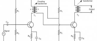
Connecting the subwoofer to the radio
It is necessary to connect the subwoofer to the radio only through an amplifier. Since the built-in power of the radio is not enough for the subwoofer to work properly, you will not get normal bass. The connection chain is simple: radio-amplifier-subwoofer. The radio transmits the signal to the amplifier. The amplifier, in turn, amplifies this signal and sends it to the subwoofer.
What is an amplifier for?
The amplifier is used to increase the volume headroom, reduce distortion and improve the sound quality of music. The built-in amplifier of the radio is not enough to drive a heavy low-frequency speaker, which will cause large distortions, the volume level will be low and, with a high probability, the subwoofer may fail or simply “burn out.”
If you have an active subwoofer, then you will not need an additional amplifier, because it is already built into the subwoofer body (). For a passive subwoofer you will have to choose an amplifier (read how to do this correctly on this page).
Parallel and combined connection
There are other connection methods, namely combined and parallel connection of capacitors. Other physical laws apply to them.
Parallel capacitors
Capacitor energy
The voltage of the entire group when connecting capacitors in parallel is equal to the voltage of the smallest of them. That is, if there is a circuit of three capacitors for 16, 25 and 50 V, then the maximum that can be applied to them is 16 V. In such a circuit, the full voltage of the power source will be applied to each individual capacitor.
The capacity of such a battery is cumulative. This is caused by the virtual addition of the areas of the plates of all individual capacitors. In the language of physics it looks like this:
Ctotal par = C1 + C2 + … + Cn.
Why is such a connection needed? It is used to increase the capacitance of capacitors, for example, in the high-voltage part of welding inverters and many powerful power supplies.
Additional Information. A parallel connection allows you to reduce the overall internal resistance of the assembly, and therefore its heating. This way you can increase the service life of the container.
The combined (mixed) compound is the most complex. It contains both serial and parallel elements. Calculation of the parameters of such circuits is given with experience. For simplicity, it is customary to study it in a triangle, breaking it down into simpler parts.
Mixed compound
From the diagram it is obvious that capacitors C1 and C2 are connected in series. Their total capacity can be calculated using the formula described above - Ctotal last. Further the scheme is simplified. There are already two parallel capacitors Ctot.seq and C3. Calculated using the above formula Ctotal par. As a result, a difficult-to-understand circuit element turns into one equivalent capacitor. This technique describes a simplification algorithm with which you can calculate much more complex capacitor figures (square, cube, etc.).
Voltage drop and total capacitance
The capacitance of a capacitor is a value that determines the amount of charge that it can store. The expression looks like this:
C = q/U.
Here q is the charge accumulated between the plates of the capacitor, U is the voltage applied to them.
The above formula represents the general case. In practice, when calculating the capacitance of a capacitor, a number of other variables should be taken into account:
C = E0ES/d,
Where:
- E0 – electrical constant equal to 8.85*10-12 F/m,
- E is the dielectric constant of the medium in which the capacitor plates are located,
- S – their intersection area,
- d – distance between plates.
The standard capacitor model is as follows.
Capacitor model
The covers are most often made of thin sheet aluminum and rolled into a roll. This is done to increase their area, because this way the capacitance of the capacitor becomes significantly larger.
The rated and maximum voltage of the device depends on the choice of dielectric installed by the manufacturer between the plates of the capacitor. This, in turn, determines its scope of application. If an excessive potential difference is applied to the plates, the field strength between them will exceed the permissible level, and dielectric breakdown will occur. This situation has a particularly detrimental effect on electrolytic capacitors and ionistors. In the event of their breakdown, the device partially or completely loses its ability to accumulate charge and subsequently becomes unsuitable for operation.
When different capacitors are connected in series and in parallel, their characteristics change significantly. This property of these parts is actively used by electronics engineers and radio amateurs. Knowing the principles of connectivity allows them to develop new devices more productively.
What is it and how does it work
In the simplest case, a capacitor consists of two conductive plates (plates) separated by a dielectric layer.
Between the plates there is a layer of dielectric - a material that does not conduct electric current well.
The plates are supplied with direct or alternating current. At the beginning, while the energy is stored, the energy consumption of the capacitor is high. As the container “fills,” it decreases. When the charge is fully charged, there is no current consumption at all, the power source seems to turn off. At this time, the capacitor itself begins to release the accumulated charge. That is, it temporarily becomes a kind of power source. That's why it is compared to a battery.
Subwoofer
Subwoofer
A subwoofer or woofer is a speaker that reproduces low frequencies or bass. The design of the woofer is such that the low-end sound is deep and rich
The installation of a subwoofer is also important - an operation that is trusted to specialists
Kinds
Bass players are usually divided into two types:
- Passive, which do not imply a built-in amplifier and filter. They necessarily require connection to an additional amplifier;
- Active subwoofers, on the contrary, imply a built-in amplifier and filters, but, nevertheless, an additional amplifier does not interfere with them.
Connection diagram for amplifier, subwoofer and capacitor
Types of bass boxes
It is customary to distinguish the following types:
- The most popular type of box is the ZYA or closed box. This is a sealed box, which is preferred by most buyers due to the relative simplicity of development and design;
- No less popular is the FI or bass reflex. Such boxes have become widespread recently due to the introduction of computer software in calculations. FI is unique in that it helps the speaker reproduce low frequencies. In this case, the box seems to become a sound source. FI enclosures produce more bass with less power than ZY;
FI box
- An isobaric design, representing a housing where not one, but two emitters are installed. They are identical and function as one speaker;
- Bandpass box is popular among professionals. It is a body consisting of two chambers. One of the chambers is completely sealed, the other is made like FI. This design provides very high-quality low bass.
Where and what are they used for?
As already mentioned, it is difficult to find a circuit without capacitors. They are used to solve a variety of problems:
- To smooth out surges in network voltage. In this case, they are placed at the input of devices, in front of microcircuits that are demanding on power parameters.
- To stabilize the output voltage of power supplies. In this case, you need to look for them before leaving.
Electrolytic cylindrical capacitors are often seen - Touch sensor (touch pads). In such devices, one of the “plates” of capacitors is a person. Or rather, his finger. Our body has a certain conductivity. This is what is used in touch sensors.
- To set the required rhythm of work. The charging time for capacitors of different capacities is different. In this case, the charge/discharge cycle of the capacitor remains constant. This is used in circuits where it is necessary to set a certain rhythm of work.
- Memory cells. The memory of computers, phones and other devices is a huge number of small capacitors. If it is charged, it is one, if it is discharged, it is zero.
- There are starting capacitors that help “accelerate” the engine. They accumulate a charge, then release it sharply, creating the required “push” to accelerate the motor.
- In photo flashes. The principle is the same. First, the charge is accumulated, then released, but converted into light.
Capacitors are common and their applications are wide. But you need to know how to connect them correctly.
How to choose an amplifier
They differ in the number (1-, 2-, 3-, 4-, 5-, 6-channel) channels and class (AB and D). Class AB - analog devices with high power ratings, but an insignificant efficiency factor that would correspond to the power reserve. Class D - digital devices with high efficiency and a large power reserve, but they cannot always boast of excellent quality. 1-channel devices Monoblocks, as they are also called, are used for subwoofers, as they operate at low load (1-2 Ohm)
They are most often presented in class D, since for a subwoofer it is not the quality that is important, but the power of the sound. They are equipped with a developed low-frequency crossover and an external volume control. 2-channel They are used to connect a pair of speakers or connect a subwoofer using a bridge connection
If the power allows, they can also be connected via a coil to a car amplifier channel. 3-channel devices are used extremely rarely today, since they have been supplanted by four-channel devices. The third channel was used to connect a subwoofer. 4-channel The most popular and widespread throughout the world. They are used to amplify power in various ways: connecting to four speakers, two speakers and one subwoofer, or two subwoofers. The versatility of their application is what determines their demand. 5-channel Used to increase the power of four channels of front and side acoustics and one subwoofer. This is an economical option that includes amplification of all components of the audio system in the car, and its compact dimensions can significantly save space. 6-channel They are used extremely rarely, as they are not in demand by ordinary consumers who prefer simpler car audio systems.
Electrical capacity
When connecting devices for charge condensation, as a rule, the technician is interested in the electrical capacitance that will result.
Electrical capacity shows the ability of a two-terminal network to accumulate charge and is measured in farads. It may seem that the higher this value, the better, but in practice it is not possible to create all possible containers in the world, moreover, this is often not necessary, since all devices used every day use standard condensation devices.
You can connect several devices for condensation in a circuit, creating one condensing container, and the value of the characteristic value will depend on the type of connection, and there are long-known formulas for its calculation.
Connecting a single-phase motor
To connect an asynchronous motor to a single-phase circuit, a voltage of 220 V is usually used. But to start it, it is necessary to create a rotary displacement torque of the rotor. For this purpose, a starting winding is used, which is additional and functions only when starting. The phase shift is set on it using a capacitor.
The capacity is selected according to the following principle. The total capacitance (operating and starting) per 100 W of power is approximately 1 µF. If you need to select capacitors to start a 1.5 kW electric motor, then it is quite easy to calculate: 1.5 x 1000: 100 x 1 = 15 µF. Thus, to connect a single-phase asynchronous motor with a power of 1.5 kW, it is necessary to use a working and starting capacitor with a total capacity of 15 μF.
Such engines have several operating modes:
- Connected additional winding to the starting capacitor. The capacitance is selected based on 70 microfarads per kilowatt of power.
- An additional winding is used throughout the entire period of operation together with a working capacitor, the capacity is about 30 µF.
- Connecting two types of capacitors at the same time.
How to properly connect capacitors
To find out how to connect a capacitor correctly, you need to figure out exactly what type it is. There are a huge variety of these electronic devices. All capacitors are divided into two groups:
- polar (electrolytic) - when connecting them, it is necessary to take into account where the part has a positive and negative contact;
- non-polar (all others) - these capacitors are capable of operating on alternating current; they do not have positive and negative terminals.
Then you need to consider the design of the electronic component. From this point of view, capacitors can be:
- Inferential. They are connected to the board using thin copper legs, coated (tinned) with a layer of solder for protection.
- For surface mounting (SMD). Mainly used in compact electronics. Very miniature, often not exceeding 1 mm in diameter.
It is also important to take into account the operating voltage of the capacitor. This is especially important for electrolytic devices of this type, because if their rated voltage is exceeded, they will most likely explode, spraying boiling electrolyte in all directions.
Important! There are two notches on the cover of the electrolytic capacitor. These weak points serve to instantly depressurize the product in the event of excessive internal pressure. When repairing and adjusting equipment, avoid directing the notches onto your face or clothing. In an emergency, hot electrolyte may splash out from them.
The maximum voltage threshold is no less critical for other types of capacitors, especially those with small dimensions and unable to withstand overloads for a long time.
The last but not least important factor to consider when connecting capacitors is their capacitance. It is measured in microfarads (after Michael Faraday). This is their main characteristic, which is why capacitors are often called electrical capacitances. In some electronic devices, this parameter can deviate significantly, both downward and upward. In others, an error of 1% is unacceptable.
Connection diagram for starting and running capacitor
Combined circuit with two capacitors The optimal option for averaging operating characteristics is a circuit with two capacitors - starting and working. In any circuit, it is very important to connect the capacitor correctly.
When the rotor is stationary, these fields lead to the appearance of moments of equal magnitude, but differently directed. Secondly, and most importantly, the author was convinced in practice that even an extremely accurate calculation is not a guarantee of the correct operation of the engine.
The latter is smaller in size and is a launcher. The position of the contacts in the junction box of a three-phase motor. Connecting a three-phase motor according to a star scheme. The junction box of a three-phase motor with the position of jumpers for connecting according to a star scheme. When a three-phase motor is connected to a three-phase network, a current begins to flow through its windings at different times in turn, creating a rotating magnetic field, which interacts with the rotor, causing it to rotate. Place one or an entire assembly of several samples with different denominations - whatever is more convenient for you.
Ideally, they should be equal to each other; if there are small differences of 30 percent, then this is not ideal, but still good. If possible, it is better to use it, since the engine will lose less power, and the voltage across the windings will be equal to V everywhere.
Connection diagrams
In this case, to connect the motor according to the “triangle” scheme, it is necessary to bring the missing ends of the windings C4, C5, C6 into the box. Therefore, the power is lost almost twice, but such an engine can be used in many low-power devices. The same applies to the organization of engine reversal.
It will be more reliable this way. Edited by A. If a three-phase electric motor is connected to a single-phase network, then this rotating torque is not created.
The starting branch will be used until the motor turns around, the working branch will be used throughout the entire operation of the engine. The diagram of a single-phase electric motor is shown in Figure 1. And connect the remaining 2 ends to the Volt power supply. To achieve the maximum starting torque, a circular magnetic field is required that performs the rotation. How to connect a motor from an old washing machine through or without a capacitor
There is no capacitor of the required value: what to do
Very often, novice home craftsmen, having discovered a breakdown of the device, try to independently discover the cause. Having seen a burnt part, they try to find a similar one, and if this fails, they take the device for repair. In fact, it is not necessary that the indicators coincide. You can use smaller capacitors by connecting them in a circuit. The main thing is to do it right. In this case, 3 goals are achieved at once - the breakdown is eliminated, experience is gained, and family budget funds are saved.
Let's try to figure out what connection methods exist and what tasks the series and parallel connection of capacitors are designed for. Often it is impossible to do without connecting capacitors into a battery. The main thing is to do it right
Connection recommendations
- The system can be connected to circuits of any power. Even in cases where one amplifier built into the head unit is working. But when installing a capacitor in an audio system equipped with an external amplifier, the first step is to start with the minimum system power (from 250 to 300 W).
- Such a device does not have to be connected only to a sound system that has a special battery. It’s just that such a “sonic” battery can quickly supply current and just as quickly unload the car’s network.
- If you are going to connect the device yourself, it is better to have protective circuits. Also, you should have on hand devices that monitor the state of the on-board network.
Be sure to follow the diagram when connecting elements. It has visual drawings showing the location of electrical circuits. All important information is also present on the diagram.
Connecting capacitors into a battery: methods of execution
There are 3 connection methods, each of which has its own specific purpose:
- Parallel - performed if it is necessary to increase the capacity while leaving the voltage at the same level.
- Consistent - the opposite effect. The voltage increases, the capacitance decreases.
- Mixed - both capacity and voltage increase.
Now let's look at each of the methods in more detail.
Parallel connection: diagrams, rules
It's actually quite simple. With a parallel connection, the calculation of the total capacitance can be calculated by simply adding all the capacitors. The final formula will look like this: Total = С₁ + С₂ + С₃ + … + Сn. In this case, the voltage on each of their elements will remain unchanged: Vtotal = V₁ = V₂ = V₃ = … = Vn.
It turns out that such an installation involves connecting all the capacitor plates to the power points. This method is the most common. But a situation may arise where it is important to increase the voltage. Let's figure out how to do this.
Serial connection: less commonly used method
When using the method of connecting capacitors in series, the voltage in the circuit increases. It consists of the voltage of all elements and looks like this: Vtot = V₁ + V₂ + V₃ +…+ Vn. In this case, the capacity changes in inverse proportion: 1/Comt = 1/С₁ + 1/С₂ + 1/С₃ + … + 1/Сn. Let's look at changes in capacitance and voltage when connected in series using an example.
Given: 3 capacitors with a voltage of 150 V and a capacity of 300 μF. Connecting them in series, we get:
- voltage: 150 + 150 + 150 = 450 V;
- capacity: 1/300 + 1/300 + 1/300 = 1/C = 299 uF.
This connection is made if there is a risk of breakdown of the capacitor dielectric when voltage is applied to the circuit. But there is another way of installation.
Good to know! Series and parallel connections of resistors and capacitors are also used. This is done in order to reduce the voltage supplied to the capacitor and prevent its breakdown. However, it should be borne in mind that the voltage must be sufficient to operate the device itself.
Mixed connection of capacitors: diagram, reasons for the need for use
This connection (also called series-parallel) is used if it is necessary to increase both capacity and voltage. Here, calculating the general parameters is a little more complicated, but not so much that it is impossible for a novice radio amateur to figure it out.
Let's create a calculation algorithm.
- the entire circuit needs to be divided into separate parts, the parameters of which are easy to calculate;
- calculate denominations;
- We calculate the general indicators, as with sequential switching.
The perfect combination
How to properly connect the alarm to the central locking of a car yourself
As mentioned above, car speakers have the right to be called that if they involve a trio (sub, amplifier and capacitor). Let's try to figure out which combination can be called ideal.
Woofer Mystery MJB 12, amplifier Sony XM-504Z and capacitor Stinger SPC111
A powerful trio that delivers perfect sound. At the same time, everything is in a budget option and you don’t have to pay extra.
Selection of amplifier, subwoofer and capacitor
Woofer Specifications
| Mystery Corps MJB 12 | High quality MDF |
| Diffuser | High quality chrome plated injection molding |
| Suspension | Butyl rubber |
| Magnet/magnetic system - weight | 40 oz/80 oz |
| Voice coil | 2" aluminum, covered with cardboard |
| Case dimensions, mm | 450/418/367 |
| Peak power, W | 250-500 |
| approximate cost | 4-5 thousand rubles |
Specifications of the Sony XM 504Z amplifier
| Dimensions, mm | 350/233/55 |
| Peak power, Ohm/W | 4/100 – 2/125 – 1/250 |
| Channels, number | 4/3 |
| Power supply | MOSFET transistors |
| approximate price | 3-4 thousand rubles |
Technical characteristics of the Stinger 111 capacitor
| Capacitance, farad | 1 |
| Voltage range, V | 16-20 |
| Internal resistance, mOhm/Hz | 1,5/120 |
| Voltmeter | Has digital/LED display red/3 segments/auto power off and on |
| Diameter, mm | 75 |
| Height, mm | 250 |
| Case color | grey |
Current when capacitors are connected in series
Electric current is of two types: direct and alternating. This is of great importance for the operation of containers.
Capacitor and DC
Marking of tantalum SMD capacitors
No direct current passes through the capacitor at all. This is also true for a line of series-connected containers. This effect is again explained by the design of the electronic device itself. The capacitor has two metal plates. In simple electrolytic devices they are made of aluminum foil. Between them there is a thin layer of dielectric (aluminum oxide). If a potential difference (voltage) is applied to the plates, current will flow, but only for a very short time until the capacitor is fully charged. Further, the movement of charge carriers will stop, because they will not be able to pass through the dielectric. At this moment we can say that the electric current is zero, and the capacitor does not allow it to pass through.
Capacitor and alternating current
With alternating current, charge carriers periodically change their direction. In the case of a household network, the change occurs 50 times per second. Therefore, they say that the frequency of the current in the socket is 50 Hz.
Important! Capacitors are able to accumulate and hold a charge for a long time. When working with containers charged from a 220 V network, they should always be discharged with a resistance of 100-1000 ohms. Failure to follow the rule will one day result in an unpleasant electric shock.
The capacitor will definitely pass alternating current, but not necessarily all of it. The number of charge carriers that can pass through this electronic device depends on the capacitance of the capacitor, the voltage applied to it and the frequency of changes in the direction of charges. Mathematically this is expressed as follows:
I = 2pfCU.
Here I is an electric current with frequency f passing through a capacitor of capacitance C, if a voltage U is applied to its plates. 2 is just a number, and p = 3.14.
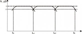
This ability of capacitors to limit alternating current is widely used in audio engineering to build various sound filters. By changing the capacitance, you can influence the signal frequency that it transmits.
Capacitance based filter
How to eliminate additional load on car wiring
Autocapacitors have one serious drawback: the ability to self-discharge. This type of electrical devices is bad for your car battery. Especially if there are a lot of them and it’s cold winter outside. To solve this problem, there are many devices on the market that are connected only when voltage appears at one terminal.
Capacitors from popular companies are equipped with a very convenient function, for example, installing a voltmeter. This is necessary for visual instrumental monitoring of voltage sags.
When connecting to the starting system, be sure to check that there is no voltage on the starting wire when parked. If there is no potential on it, then the car's network will be blocked from the capacitor. It is very easy to perform manual switching yourself. To implement this, you just need to use a relay. The switch can be placed in any place where it is convenient.
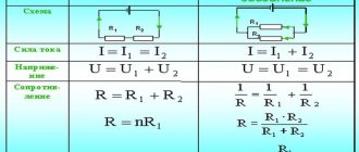
Laws of series and parallel connection of conductors
For a detailed understanding in practice of both types of connections, we present formulas explaining the laws of these types of connections. Power calculations for parallel and series connections are different.
In a series circuit, there is the same current in all conductors:
I = I1 = I2.
According to Ohm's law, these types of conductor connections are explained differently in different cases. So, in the case of a series circuit, the voltages are equal to each other:
U1 = IR1, U2 = IR2.
In addition, the total voltage is equal to the sum of the voltages of the individual conductors:
U = U1 + U2 = I(R1 + R2) = IR.
The total resistance of an electrical circuit is calculated as the sum of the active resistances of all conductors, regardless of their number.
In the case of a parallel circuit, the total voltage of the circuit is similar to the voltage of the individual elements:
U1 = U2 = U.
And the total strength of the electric current is calculated as the sum of the currents that exist in all conductors located in parallel:
I = I1 + I2.
To ensure maximum efficiency of electrical networks, it is necessary to understand the essence of both types of connections and apply them expediently, using the laws and calculating the rationality of practical implementation.
Why do you need a capacitor for a subwoofer?
To understand why a car is equipped with a capacitive capacitor, it is worth remembering Ohm’s law for a complete circuit. It is he who will help you understand what happens when the subwoofer suddenly reaches maximum volume.
- Each battery has an electromotive force parameter, which depends on the device’s capacity, its internal resistance and other characteristics.
- Until the moment when the amplifier and the entire sound installation as a whole do not exceed the battery capacity, the wiring operates normally.
- During periods when the subwoofer sharply increases volume and power consumption, the battery is physically unable to meet the needs. Its electromotive force is not enough to maintain a stable voltage.
As a result of intensive power extraction for sound, the following occurs: operating currents increase, the battery cannot meet the needs and the voltage of the on-board network drops sharply. As a result, there is a drawdown of the subwoofer (the speakers choke), and the functioning of the amplifier becomes abnormal.
It is to stabilize the operation of the on-board network that electrolytic capacitors are needed, which release power at the time of peak load. It is worth understanding that the average speaker in a car, like the entire audio system as a whole, does not always work even at rated power. During these periods of low consumption and currents, the machine uses its generator to charge not only the battery, but also the installed storage device.
During periods of increased consumption, the capacitor discharges. This allows you to get truly better sound without power drops and failure to gain sound volume.
Mixed connection of conductors
Series and parallel resistance circuits can be combined in one electrical circuit if necessary. For example, it is possible to connect parallel resistors in a series circuit to another resistor or group of resistors; this type is considered combined or mixed.
In this case, the total resistance is calculated by summing the values for the parallel connection in the system and for the series connection. First, it is necessary to calculate the equivalent resistances of resistors in a series circuit, and then the elements of a parallel circuit. Serial connection is considered a priority, and circuits of this combined type are often used in household appliances and appliances.
So, by considering the types of conductor connections in electrical circuits and based on the laws of their functioning, you can fully understand the essence of the organization of circuits of most household electrical appliances. For parallel and series connections, the calculation of resistance and current is different. Knowing the principles of calculation and formulas, you can competently use each type of circuit organization to connect elements in the optimal way and with maximum efficiency.
Features of a device with alternating current
To determine whether alternating current will flow, the device must be connected to the appropriate circuit.
The main source of electricity in this case should be a device that generates alternating current. Direct electric current does not flow through the capacitor, but alternating current, on the contrary, does, and the device constantly resists the electric current passing through it. The magnitude of this resistance is related to the frequency. The dependence here is inversely proportional: the lower the frequency, the higher the resistance. If you connect a condenser to an alternating current source , the maximum voltage value here will depend on the current strength.
How to check the quality of connection of capacitors in a circuit
The most ideal case is when we have an appropriate type of voltmeter on hand. It costs around one thousand rubles.
This is not so much, considering that together we get a device for measuring resistance, direct and alternating voltage, and currents.
The socket for measuring the capacitor (see photo on the left) consists of two narrow slots into which the legs should be inserted.
According to our observations, there is no difference which side to insert the electrolytic capacitor. Although it is better to follow the instruction manual.
Then you need to somehow mark them, or lay them out according to a diagram drawn on paper, where you can put all the numbers (by the way, this is usually done in all Chinese technology).
Then you should calculate using the formulas exactly what value should be obtained and check it with a tester. Does not work? This means that the quality of the contacts is poor - use less twisting.
CAPACITOR CONNECTIONS
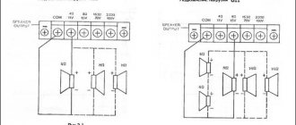
If it is necessary to increase the total capacitance of the capacitors, then they are connected to each other in parallel (Fig. 9, a
). With this connection method, the total area of the plates increases compared to the plate area of each capacitor. The total capacitance of capacitors connected in parallel is equal to the sum of the capacitances of the individual capacitors and is calculated by the formula Ctot = C1 + C2 + C3+
(10)
This can be confirmed as follows.
Capacitors connected in parallel are under the same voltage, equal to U volts, and the total charge of these capacitors is equal to q coulombs. In this case, each capacitor respectively receives a charge q 1, q 2, q 3, etc. Therefore,
q total = q 1 + q 2 + q 3 +
From formula (8) it follows that the charge
qtot = Ctot U (11)
and charges q 1 = C 1 U; q 2 = C 2 U; q 3 = C 3 U.
Substituting these expressions into formula (11), we obtain:
C total U= C 1 U + C 2 U + C 3 U.
Dividing the left and right sides of this equality by the value U equal for all capacitors, after reduction we find:
C total = C 1 + C 2 + C 3
Example
. Three capacitors with a capacity C 1 = 2 μF; C 2 =0.1 µF and C 3 =0.5 µF are connected in parallel.
Calculate their total capacity.
C total = C 1 + C 2 + C 3 = 2 + 00.1 + 0.5 = 2.6 μF.
The total capacitance of capacitors having the same capacitance and connected in parallel can be calculated using the formula
Ctot = Cn, (12)
where C is the capacitance of one capacitor,
n is the number of capacitors.
Example.
Five capacitors with a capacity of 2 μF each are connected in parallel. Determine their total capacity.
C total = Cn = 2·5 = 10 μF.
Capacitors are connected in series (Fig. 9, b) when the operating voltage of the installation exceeds the voltage for which the insulation of one capacitor is designed. In this case, the right plate of the first capacitor is connected to the left plate of the second, the right plate of the second to the left plate of the third, etc. The total capacitance of the capacitors with this connection decreases. The reciprocal of the total capacitance of capacitors connected in series is equal to the sum of the reciprocals of the capacitances of individual capacitors:
This can be confirmed as follows. The total voltage on the capacitors U is the total on each capacitor U 1, U 2, U 3, then
U total = U 1 + U 2 + U 3.
From Formula (8) it follows that the voltage
U total = (14)
and the voltage
Substituting these expressions into formula (14), we obtain:
Let us divide the left and right sides of this equality by the value q and after reduction we find:
Example. Three capacitors C1=2 µF, C2=4 µF and C3=8 µF are connected in series. Determine their total capacity.
If capacitors having the same capacitance are connected in series, then their total capacitance can be calculated using the formula
Example.
Four capacitors with a capacity of 1000 pf each are connected in series. Determine their total capacity. Solution.
If two capacitors of different capacitance are connected in series, then their total capacitance can be found using the formula
Example.
Two capacitors C 1 =200 pF
and C 2 =300 pf connected in series. Calculate their total capacity.
As can be seen from the above examples, the total capacitance of capacitors connected in series is always less than the smallest capacitance included in the connection.
Capacitors are selected according to their capacitance and the operating voltage that is supplied to its plates when connected to the circuit. When the voltage exceeds the permissible value, a breakdown of the dielectric in the capacitor occurs. This voltage is called breakdown voltage. The breakdown of the dielectric is accompanied by an electrical discharge - a spark with a characteristic crackling sound. A capacitor with a broken dielectric is not suitable for use.
Each dielectric has a certain electrical strength, i.e., the ability to resist breakdown. Electrical strength (Table 2) is usually measured in (v/cm
) and is determined by the formula
where U is voltage, V
d—dielectric thickness, cm.
Many people, when assembling a particular device, often think about how to connect capacitors in a parallel or series connection. Not every denomination is produced by industry, so the task of providing a design with a bunch of containers occurs here and there. When connected in parallel, the denominations are added, and when connected in series, a more complex formula is used. There are also tuning capacitors; these are definitely included in circuits where it is necessary to provide the necessary resonant characteristics. In this case, it is also necessary to solve the above problem. The problem is that often the assembly of some kind of induction heater is literally done on your knees, there is a whole pile of iron, there are no pads at hand, and you are too lazy to solder - what to do?
Quality of passive elements
Capacitors, especially when they are located on the output signal line, greatly affect the sound quality of an audio system.
There are several factors that determine the quality of CAP, undoubtedly very important for audio:
- Tolerance and actual capacity required for use in filters.
- The dependence of capacitance on frequency, so 1 microfarad at 1,000 Hz does not mean 1 microfarad at 20 kHz.
- Internal resistance (ESR).
- Leakage current.
- Aging is a factor that will develop over time for any product.
The best choice of capacitor applications depends on the circuit application and the required capacitance:
Range from 1 pF to 1 nF - control and feedback circuits. This range is primarily used to eliminate high frequency noise on an audio channel or for feedback purposes such as a Quad 606 amplifier bridge. An SGM capacitor in audio is the best choice in this range. It has very good tolerance (up to 1%) and very low distortion and noise, but is quite expensive. ISS or MKP is a good alternative. Ceramic CAPs should be avoided on the signal line as they can cause additional harmonic distortion of up to 1%. From 1 nF to 1 µF - coupling, decoupling and oscillation suppression. They are most often used in audio systems and also between stages where there are differences in DC level, vibration elimination and feedback circuits. Typically, film capacitors will be used in this range up to 4.7 microfarads. The best choice of capacitor for sound and audio is polystyrene (MKS), polypropylene (MPP). Polyethylene (MKT) is a lower cost alternative. 1 F and higher - power supplies, output capacitors, filters, insulation. The advantage is very high capacity (up to 1 Farad). But there are several disadvantages. Electrolytic CAPs are subject to aging and drying. After 10 years or more, the oil dries out and important factors such as ESR change. They are polarized and must be replaced every 10 years or they will negatively affect the sound. When designing the signal line electrolyte interconnect circuit, problems can often be avoided by recalculating the time constant (RxC) for low capacitance below 1 microfarad. This will help determine which electrolytic capacitors are better for sound
If this is not possible, it is important that the electrolyte is less than 1 VDC and a high quality CAP is used (BHC Aerovox, Nichicon, Epcos, Panasonic)
By choosing the best solution for each program, the developer can achieve the best sound quality. Investing in high-quality CAPs has a positive impact on sound quality more than any other component.
Comparison of different options
| Capacity | Voltage | |
| Parallel | Increases | Doesn't change |
| Sequential | Decreases | Increases |
| Mixed | Changes | Increases |
To select a connection, you can use the following table. On the left is the type of connection of devices, on top is the properties of the device for charge condensation.
If you need to increase the capacity, then you need to use a parallel connection, and if you increase the voltage, then a serial connection. If both are required, then it will be necessary to calculate the mixed connection of capacitors in the circuit.
RC chain
RC chains are of integrating and differentiating types.
Fig. 10. Connecting an integrating-type RC circuit to a voltage generator.
What happens in this circuit if switch S1 is closed?
Question: And if you power such a circuit from a current generator, how will the voltage across the capacitor increase?
As noted above, the current at the first moment after applying the voltage will be equal to I=U/R, since the capacitor is discharged and the voltage on it is 0. And for some time, while the voltage on the capacitor Uc is small compared to U, the current will remain almost constant. And when charging a capacitor with direct current, the voltage across it increases linearly.
Uc=Q/C, and we remember that current is the amount of charge per second, that is, the rate of charge flow. In other words, the charge is the integral of the current.
But all this is close to the truth at the initial moment, while the voltage on the capacitor is low.
What it really comes down to is that the capacitor is charged by a constant current. A direct current is produced by a current generator. (See the question above) If the voltage source produces an infinitely large voltage and the resistance R also has an infinitely large value, then in fact we already have an ideal current generator, and external circuits do not affect the value of this current.
Expert opinion
It-Technology, Electrical power and electronics specialist
Ask questions to the “Specialist for modernization of energy generation systems”
Series connection As a rule, on electrolytic capacitors on the case, a contrasting stripe is marked on the negative terminal of the cathode; for tantalum capacitors in yellow rectangular cases, the positive terminal, the anode, is marked with a stripe. Ask, I'm in touch!
Tags
use capacitors in parallel with capacitors connect electrolytic capacitors for Capacitors connecting capacitors connecting capacitors connecting capacitors connecting capacitors connecting capacitors connecting capacitors and parallel connections are recommended in parallel with capacitors Parallel connection of series connection is reduced series connection of capacitors parallel connection of capacitors Parallel connection of capacitors in parallel connection Series connection of capacitors mixed connection of capacitors parallel connection of capacitors Types of connection of capacitors Parallel connection of capacitors and the voltage is divided by the operating voltage .use serial and When connected in series, however SERIAL practically
cover articlenecessary drives source
digital electronics computing embedded systems
Making a simple tuning capacitor for VHF with your own hands
If you are an avid radio amateur and like to assemble radios, then you may have noticed that the range of variable tuning capacitors at suppliers of electronic components has somewhat decreased. There was a time when almost every radio receiver had at least one tuning capacitor, but now with the advent of the varicap and frequency synthesizer, such an antenna circuit tuning capacitor is a rarity. They're still in production, but they're not cheap, and they won't show up in your component drawer as quickly as they once did.
Fortunately, the variable capacitor is a surprisingly simple device. Moreover, you can make it yourself; at least a capacitor with a capacity of several tens of picofarads is assembled from scrap materials.
To assemble a homemade capacitor you will need a bolt, a pair of nuts, a piece of coated copper wire (length 30 cm, caliber AWG22, i.e. diameter 0.64 mm) and a small piece of PCB.
To begin, screw the nuts onto the bolt and apply tin to one of the faces of each nut, then solder this bolt with nuts to a piece of copper PCB, as shown in the pictures below.
It is advisable to take a bolt 16 mm long. If you don’t have one at hand, you can take a longer one, but you’ll have to cut it to length. Now wrap the edge of the bolt with copper wire. Make 12 rings, after the twelfth turn, cut off the excess ends of the wire, leaving approximately 12-15 mm on each side.
The picture below shows the penultimate step. At this stage you need to make a small plastic spacer and place it between the nuts. This is necessary to securely fix the structure when the bolt rotates while setting up such a homemade capacitor. A piece of such plastic can be from anything and any type of plastic. In this case, a piece of plastic pipe was used.
The final step is to simply bend the outer end of the coil wire towards the inner end, then cut off the excess. Next, take a knife or other blade and remove the enamel from the end of the wire. Finally, take a cut piece of wire, strip it all off and solder it to a piece of PCB between two nuts. Make sure that both ends of the coil are about 12-15mm long. Now you can connect your homemade variable tuning capacitor to your radio with these ends.
The wire soldered to the PCB acts as the rotor and the wire coming from the coil acts as the stator. Using such a capacitor, you can obtain a capacitance from 5 to 27 pF.
Legend
With the abbreviated system, letters and numbers are applied, where a letter indicates a subclass, a number indicates a group, depending on the dielectric used. The third element indicates the registration number of the product type.
We recommend studying Recuperation or conversion of kinetic braking energy
With a full symbol, the parameters and characteristics are indicated in the following sequence:
- symbol of the design of the product;
- rated voltage of the product;
- nominal capacity of the product;
- permissible deviation of capacitance;
- temperature stability of the product container;
- rated reactive power of the product.