After reading the title, many will not even look: the topic is so expounded - what could be new here? Yes, many showed their alterations, characterizing them in excellent terms. I also want to contribute.
And let others evaluate the quality of this. Also, in my opinion, 6P3S lamps are undeservedly omitted. In my opinion, you just need to know how to “cook” them;)
The purpose of this upgrade is to eliminate the problem of output tube failure due to uncontrolled currents, as well as improve sound quality.
Many consider 6P3C lamps to be extremely unreliable, and recommend throwing them away immediately and replacing them with something else. I agree that the manufacturing quality of these lamps leaves much to be desired.
Especially in the last years of their release. Here there is a loss of vacuum due to cracks, interelectrode short circuits, etc. But those lamps that managed to avoid defects are quite good.
And the reverse currents of the control grids, the growth of which leads to the melting of the cylinders, can be stabilized. The proposed modernization makes it possible not only to stabilize the bias voltages on the grids of the output lamps, but also to maintain the dissipated quiescent power at the anodes stable when the supply voltage of the electrical network changes.
The typical “Priboy” circuit does not guarantee the reliability of the device even with the use of a voltage stabilizer, as some people suggest on the Internet.
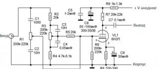
Power amplifier modification circuit
The proposed circuit consists of a phase-inverted and output stage, without OOS. To stabilize the bias voltages and increase the gain of the phase inversion stage, decoupling cathode followers on a 6N6P lamp were used.
The drive of the output lamps is sufficient with a good margin, because gain FI 50...60. To ensure the required bias source voltage and its correction, some changes have been made to the power supply board.
The rectifier is converted into a doubler, for which 2 capacitors and a diode are added. There is enough space for installing electrolytes on the board. A zener diode and resistor are added to correct the offset.
The zener diode voltage sets the desired decrease in the quiescent current of the output lamps as the supply voltage increases, and vice versa. Wires -100V and +33V are thrown additionally.
Rice. 1. Scheme for upgrading the Priboy 50UM-204S tube amplifier.
As for the sound quality, the circuit operates without OOS, which eliminates the “transistor” sound. To reduce odd harmonics, the quiescent currents of the output lamps are set as high as possible.
For example, for 6Р3С the maximum permissible anode current is: Pa max/Ua = 40/420 = 95mA. But such a current is not necessary, 60...80mA is enough (approximately 0.65...0.85V at the cathodes).
Install at a network voltage of 220. When it decreases, the current will increase, and when it increases, it will fall. The phase inverter can be adjusted according to the equality of the amplitudes of the build-up (you can adjust the change to zero on the 6N2P cathodes).
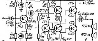
And this is what the mind diagram looks like without reference to a specific device:
Rice. 2. Schematic diagram of a tube power amplifier for 6N2P, 6N6P, 6R3S.
At the moment, there is a tested scheme for converting the “surf” with triode connection of output lamps, delivering 30 watts per channel.
Sound of "Surf"
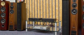
This story began in the fall of 1991, when I was puzzled by the purchase of a power amplifier for my home stereo system.
The “complex” then included: a first-class reel-to-reel tape recorder (with a power amplifier), a top-class reel-to-reel tape recorder (without a power amplifier), a Vega EP-122 electronic control unit (without a phono stage) and a pair of Radiotehnika S-90 speakers. The problem with buying an amplifier was that the country was going through difficult times, and everything was being swept away from stores. At this time, the Priboi 50UM-204S amplifiers went on sale. They were collected in Taganrog, they cost 350 rubles. These amplifiers were not particularly popular. Firstly, they had a rather unsightly appearance. Secondly, they were tube-based. And this is at the end of the 20th century!
I always liked tube electronics, I had enough money, and I decided to buy it. How many times I regretted it, you will find out further. TL/DR:
I regretted buying a tube amplifier exactly once: after a week of operation, the amplifier caught fire so bad that I had to put it out.
And then - not even once! The design of the amplifier is very simple. It is based on a welded frame made of aluminum corners. Front panel made of aluminum. The bottom and back walls are plastic. A U-shaped steel casing is put on the body. Overall dimensions of the amplifier: 430x400x163 mm. Amplifier weight without packaging: 18 kg.
The weight of the amplifier is given by three transformers: two output and one power.
The developers decided not to complicate the design of the output transformers; they did not wind the windings in a “sandwich”, alternating layers of primary and secondary. But they did not spare the “hardware” for the transformers, but tightened it so tightly that the transformers do not emit any vibrations during operation. The front panel of the amplifier contains: a power button, a power indicator and a double slider level control. On the back wall there is a power cord input, a fuse socket, a line input socket and terminals for connecting speakers.
The level regulator has an original design. The photo below shows its view on the right and left:
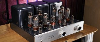
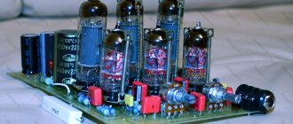
The output stages of the amplifier are assembled on powerful 6Р3С-1 beam tetrodes. The same tubes worked for decades in U-100U4.2 broadcast amplifiers. At the school where I studied, by the way, there was one like this.
The output stages are push-pull (Push-Pull, PP), the lamp switching is pentode. The offset on the control grids is fixed, not “automatic”. There is negative feedback through the RC circuit from the speaker output to the amplifier input. The components are mounted on printed circuit boards. No “audiophile problems”, in short.
When I first turned it on, “Surf” shocked me because it didn’t reveal itself to be anything. The indicator glowed, the glow of the lamps shone through the casing grilles, and the speakers did not make a sound. There was neither the “rustling” characteristic of transistor amplifiers, nor the background of alternating current, only soft clicking sounds were heard when moving the volume control sliders.
The first listening made a favorable impression. The amplifier gave very good “detailing”. Everything was darkened by the fact that the S-90 with this amplifier from time to time cheerfully grunted with “bass”. These speakers did not have enough “tops” from the amplifier.
One of my friends had Soyuz 130AS-002 speakers. He didn’t like them for their “clumsy” appearance, and he decided to exchange them for my “S-90s”.
It turned out that the Priboi 50UM-204S amplifier and the Soyuz 130AS-002 acoustic systems were simply made for each other. At the place where “Radiotehnika S-90” “grunted”, “Soyuz 130AS-002” “boomed” and blew away the newspaper lying next to it with a stream of air from the bass reflex.
By an incredible coincidence, the mass of the Soyuz 130AS-002 speaker system without packaging is also 18 kg.
There is a fuse in the cathode circuits of the amplifier's output tubes. As it turned out, he was not superfluous there at all. But at the factory, instead of a 0.4 A fuse, a 4 A fuse was installed.
The amplifier caught fire like this: the glass container at the output lamp melted, the resistors in the cathode and screen grid circuits burned out, but the fuse remained intact! Fortunately, the transformer was not damaged.
It is a well-known fact that amplification stages on vacuum tubes are prone to self-excitation. The 6Р3С-1 lamps (manufactured in 1989), purchased together with the amplifier, turned out to be especially prone to self-excitation and “burned out” in a similar way within six months. Fortunately, the fuses worked normally in these cases.
I replaced the “burnt out” 6Р3С-1 with lamps manufactured in 1977, which I managed to “get.” I selected the lamps in pairs, so that with the same negative bias on the control grids they would have the same quiescent current.
I check the modes of these lamps once every five years; of course, there is a loss of emission, but not severe. And they have been working for almost thirty years without replacement.
There are a huge number of recommendations on the network for remaking the Priboi 50UM-204S amplifier. It may seem that the amplifier consists of only shortcomings.
I always proceeded from the fact that the number “204” in the name of the amplifier means that it belongs to the equipment of the 2nd complexity group. This is the lowest category for amplifiers according to GOST 24388-88.
But is the Priboi 50UM-204S amplifier really that bad? In 2005, along with the AudioVideo Salon magazine, I received the AudioDoctor FSQ test disc. The disc has 14 main tracks and 2 bonus tracks. The booklet tells you what is recorded on the tracks, what it should sound like, and what to do with the equipment if the track doesn't sound right.
On my amplifier and speakers, all tracks on the test disc sound as they should. Agree that this is not bad at all for “equipment of the 2nd complexity group”!
Over its long life, the amplifier has survived a complete replacement of electrolytic capacitors; selection of resistor values connected to the cathodes and screen grids of the output lamps; replacement of output lamps with selection in pairs. That's all!
The Priboy 50UM-204S amplifier combines my love for music and my love for tube electronics. This amplifier, coupled with the Soyuz 130AS-002 speaker, reproduces both classical music from vinyl and industrial or trip-hop from CDs equally well.
Here, for example, is what the finale of the Russian dance from P.I.’s ballet sounds like. Tchaikovsky's "Nutcracker":
The practice of thirty years of operation of my Priboy confirms the rule: simple circuits require the selection of components.
In this case, the Priboi 50UM-204S amplifier was completely unlucky. The equipment was put into production during the collapse of economic ties in the country. In terms of configuration, the amplifier resembles a vinaigrette: high-quality capacitors K73-16 are interspersed with “waste” capacitors K10-7; “discrepancy” in the types of resistors in the level regulator; low-quality 6Р3С-1 lamps, finally.
None of my fellow music enthusiasts decided to buy a tube amplifier.
From the transistor sound of a “surf” amplifier to a tube one
(C) AUDIO STORE 1/1996
From the editor: The proposed modification of the amplifier is designed for a trained radio amateur. Remember that you will have to deal with high-voltage circuits - take care of your life. The Audio Store magazine is not responsible for the consequences of the alteration undertaken, although consultations on questions sent by mail are possible. Commercial use of the above amplifier design will be prosecuted by law.
If you want an amplifier that can naturally reproduce the human voice, violin and piano sounds, you should withdraw at least $2,000 from your account and, using the advice of mentors from the Audio Store, purchase a simple “Manley” or “Audio Note” . Another way is to buy a “Surf” tube amplifier at the clothing market for $50 and assemble an amplifier yourself from its parts, the sound quality of which will meet your highest requirements. The idea of making a “high-end” amplifier out of the “Priboi” came to my mind a year ago, when in the nearest grocery store, among bottles of strong drinks and sweet Twix pairs, I discovered a Priboi 50 UM 204C looking forlornly out of a dark corner.” It cost only 60 thousand rubles, so I bought it, one might say, without looking, without even checking whether it was in working condition. The first thing I did after dragging this heavy thing home was to remove the output transformer from it, and then measure its transformation ratio and bandwidth. The result seemed encouraging to me, so without wasting any time, I connected the removed output transformers to my amplifier using EL34 tubes (in triode connection) and began to carefully listen to Paganini’s violin concerto performed by I. Menuhin. “It’s not that bad at all,” I finally said to myself and without thinking twice I went down for another “Surf”. Later, I advised many of my friends to buy this amplifier, and privately thanked Volodya Starodubtsev, the author of the first domestic tube amplifier (the first after the period of their oblivion in the 60s) for a suitable output transformer, an easy-to-remake design and a reasonable price even for a set of parts .
1. The electrical circuit of the amplifier should be extremely simple (simplicity is most easily assessed by the number of elements, soldering and wires used in the amplifier).
2. All electrical elements, including resistors, capacitors, connectors, connecting wires (including in the power supply), as well as solder must be carefully selected and harmonized with each other in terms of sound.
3. The amplifier should not contain even small negative feedback.
4. If possible, the output impedance of the amplifier should be active, independent of the instantaneous values of the signal, and should not exceed half the rated impedance of the loudspeaker (this requirement is met only in amplifiers with a triode output operating in class “A”).
5. Each channel of the amplifier must have its own power supply, carefully cleared of ripple and interference (you should pay attention to the fact that the quality requirements for the power supply of an amplifier using triodes are an order of magnitude higher than the corresponding requirements for the power supply of an amplifier made using pentodes).
I cannot agree with the opinion of Peter Qvortrup, who believes that only single-ended amplifiers are a panacea for all ills ("AM N4 (5) 95, p. 40). I believe that a carefully designed push-pull, especially in terms of the bass reflex and its connections with the output tubes, will lead you to “push-pull heaven”. However, in order to be convinced of the real advantages of tubes over transistors, you will have to make some sacrifices, namely: when you turn on the 6P3-1 output tubes with a triode and transfer the amplifier to class A, you will lose approximately three-quarters of the amplifier's output power. Therefore, despite the “soft” clipping when overloaded, it is better to refrain from altering the “Surf” until you are sure that the sensitivity of your speakers is no less than 90 dB/W/i. In any textbook of the 50s on amplifiers, you can read that the efficiency of a push-pull amplifier using tubes does not exceed 78% in class B with pentodes, 35.5% in class B with triodes, and 25% in class A with triodes.
Unfortunately, even these values remain unattainable due to the imperfection of the anode characteristics of the output lamps. Therefore, so that the owners of the Priboy do not think that they want to be deprived of its main advantage - the output power, I will dwell in detail on the calculation of a push-pull output stage operating in class "A" on triode-connected 6P3-1 lamps. For the calculation, we will use the data for the 6P3-1 lamp given in the reference books. For our purposes, we found little: the maximum permissible power dissipation on both anodes P a max - 40 W and the maximum permissible voltage on the second grid Ua2max = 300 V.
In the triode connection of the lamp, this voltage becomes the maximum permissible for the anodes.
Unfortunately, the anode characteristics of a triode-connected lamp are not available in reference books, so they had to be determined experimentally,
I must apologize for possible measurement errors, since my measuring setup consisted only of *U\TPa, a rectifier and a tester.
Having previously protected the lamp from RF excitation by connecting a 1 kohm resistor into the circuit of the first (control) grid and a 100 Ohm resistor between the anodes and the second grid. It did not take much time to determine the anode characteristics: for subsequent calculations it is quite enough to have the dependence of the current of the anodes connected in parallel Ia on the voltage across them Ua with the bias voltage of the first grid equal to zero (Uc1=O). The dependence I obtained is shown in At large values of the anode current, it has the form of a straight line, the slope coefficient of which is equal to the internal resistance of the lamp Ri = (^Ua/^Ia) - 288 Ohms, and at small values (in our case, with Ia less than Iamin = O.O5A ) turns into a curve. In this section of the anode characteristic, a rapid increase in the internal resistance of the lamp is observed, which limits the power supplied to the load. By plotting the dependence of the anode current on the voltage on it (at Uc1=O) the boundaries of the permissible lamp modes - the maximum power dissipated on the anodes Pamax and the maximum permissible voltage on the second grid Uc2max - as well as the dotted line indicating the minimum anode current Iamin, we obtain a limited the area in which it is desirable to place the instantaneous modes of the 6P3-1 lamp, switched on by a triode, operating in the output stage of class A. If we assume that the anode load of the lamp is active with an optimal resistance K, - 2R, - the triode can deliver the greatest power to this load, - then when the signal is amplified, the lamp mode will “draw” the so-called load line (see Fig. I), which has a slope of -1/Ra,. To obtain the highest output power, we will place the load line as close as possible to the Pamax curve, while it will be limited on the left by the anode characteristic at Uc1 = O (with coordinates Uamin = 120.5 V and Iamax = 0.325 A), and on the right - by the value of the anode current Iamin = 0.05 A at anode voltage Uamax = 299.5 V. Let me remind you that the exit of the instantaneous mode of the lamp to the left beyond the designated area is prevented by the current in the circuit of the first grid, and to the right is prevented by the increase in the internal resistance of the lamp.
The loudspeaker resistance, converted through the output transformer into the load of the anodes of the output tubes, is actually complex in nature. It can only be considered active as a first approximation.
Now let's look at the tube mode when there is no signal at the amplifier output. This is the so-called lamp rest mode. In the output stage of the Aon class, it is located approximately at the point dividing the load line shown in Fig. 1 into two equal parts. In our case, this mode has the following coordinates:
x+Uamin) (299.5+120.5) Ua0 = ————- = ————- = 210 V 2 2 (Iamax+Iamin) (0.325+0.05) Ia0 = ————- = ———— = 0.186 A 2 2
In the transformer output stage, the quiescent voltage U * can be considered equal to the voltage supplied to this stage from the power supply, while the quiescent current Ia0 is set by applying a negative bias to the first grid of the lamp relative to its cathode. In the proposed amplifier, the bias voltage is determined. experimentally: Uc1 = -15 V. In push-pull amplifiers of class A (including the proposed amplifier), the quiescent current is set automatically due to the voltage drop across the resistor common to the cathodes of the output lamps relative to the control grids, which have a zero DC potential. Once the rest mode has been determined, you can begin to calculate the maximum power supplied by each output stage lamp to the load. If you look closely at Fig. 1, you will notice that the required power is equal to the area of any of the shaded triangles. Using elementary concepts from geometry, we will evaluate this power quantitatively, then double it and obtain the maximum output power of an amplifier operating in class A using 6P3-1 tubes in triode connection:
Rout max=[U0-Un-(2Ia0-iamax)Ri0](Ia0-Iamin)==[210-23-(0.375-0.05)x300](0.186-0.05)=12.2 W
where Un=28 V is the drive voltage (see Fig. 1); Ri0 is the internal resistance of the lamp in rest mode (according to measurements, Ri0 = 300 Ohm).
This stereo amplifier is made according to a push-pull circuit, in the original it is three-stage - a 6ZH32P pentode is used in the input stage of the voltage amplifier, the phase inverter is made on a 6N6P double triode according to a circuit that is a variation of the so-called. "load-sharing schemes". The output stage uses two 6P3S-1 double beam tetrodes, with both tetrodes in the lamp cylinders connected in parallel.The converted amplifier is a two-stage amplifier, the input stage, which is also a bass reflex, is made on two 6F12P triode-pentodes, but in this case only the triodes of these lamps are used (the unused terminals of the pentodes are connected to a common wire).
This bass reflex is the so-called. “circuit with a long tail”, operating modes of triodes of 6F12P lamps: Egc≈1.3 V, Eac≈196 V, Ia≈7.7 mA, Ra=25 kOhm. The additional negative voltage source (≈105 V) required for operation of this circuit is obtained using winding 7-8 (42 V) of the power transformer and a voltage-doubling rectifier. The bass reflex operating mode is adjusted using a tuning resistor SP5-16VA 10 kOhm.
The output stage of the modernized amplifier uses 6S19P-V triodes; their “quartet” (in pairs for the left and right channels) was selected from about one and a half dozen available tubes. For 6S19P-V, automatic bias is applied - in their cathodes there are two, connected in parallel, “ceramic” resistors of 510 Ohms, with a power of 10 W each, lamp operating modes: Egc≈39 V, Eac≈150 V, Ia≈76 mA, Ra ≈1300 Ohm (at 8 Ohm load). The power dissipated at the anodes of the lamps (11.4 W) slightly exceeds the rated power (11 W), but the amplifier has been in operation for many years, and no problems have been noted with the 6S19P-V lamps.
The anode voltage source (rectifier) in the amplifier is “two-story”, the lower “floor” provides power to the output stage (≈192 V), the total capacitance of the filter capacitors here is 4000 μF. Accordingly, the sum of the voltages of the lower and upper “floors” is the supply voltage of the input stage / bass reflex (≈389 V).
Metal-paper capacitors of the K42U-2, MBGO-2 and OMBG-2 types are used as transition (interstage) and also blocking capacitors in power circuits in the converted device. The volume control is a dual variable resistor ALPS 50K RK18 DX2.
Circuit diagram of the power amplifier “Priboy 50UM-204S” using 6F12P and 6S19P-V lamps: