Every music lover knows that built-in acoustics or multimedia computer speakers are not capable of producing high-quality sound from any source. Therefore, a passive speaker system with an amplifier is required. The latter, by the way, affects the sound quality in the most decisive way. It determines how many watts and kilohertz your speakers can produce.
Modern Hi-End amplifiers are incredibly expensive. Not everyone can buy them. However, there are domestic models (even from the last century) that provide acceptable sound quality and cost a penny. Soviet amplifiers have always been rated among music lovers. And “Vega 50U-122S” (amplifier) is no exception. Many people criticize this amplifier for all its worth, while others prove the opposite with crazy tenacity. Who is right? To do this, you need to consider the technical characteristics of the device, study reviews from owners and form your own point of view. Only after this can any conclusions be drawn.
Background
Many, many years ago, when the main source of sound recording was a cassette recorder, when stories about the influence of wires on sound seemed something distant, and the music touched the soul even when played from a portable radio and was bought by Vega for 500 paper rubles.
Naturally, in addition to this, I bought a KR590KN3, because someone managed, as always, to burn the input switch. After that, her life was hard. Yes, she played as best she could, and sometimes it even seemed good, sometimes she “pleased” with another bunch of unfortunate, broken output transistors and then played again.
Time flows and gradually “The desire to Throw Vega Out the Window” became stronger, but the lack of another decent amplifier stopped it, and it was also stopped by a phrase that was once seen in one of the forums and remembered. It sounded something like this: “An engineer who cannot fix a faulty Vega is, in general, not one.”
Yes, I could fix it, but it all usually came down to replacing burnt out parts.
And then there was a long break, because there was a better amplifier, but time again brought me together with this miracle of engineering. I had to thoroughly understand it, testing many of my guesses in practice. This article shows the result, what happened in the end.
Sound quality
This is a “double-edged sword”. Judging by how this amplifier is reviewed, its sound quality cannot satisfy discerning audiophiles. However, for an ordinary person, the quality of “Vega” is more than enough. It has the ability to reproduce sound ranging from 20 hertz to 25 kilohertz. This range is quite enough to capture the full picture of the musical composition. The Vega 50U-122S amplifier, reviews of which are not very good, is quite suitable for home use, because the sound quality is fully consistent with average needs.
Acoustic systems also play an important role in sound quality. If you use speakers with an impedance very different from the nominal one, then you can’t expect high-quality sound. For the Vega 50U-122S amplifier, for which no instructions are required at all, you need to select speakers based on the technical characteristics of the amplifier itself. This is the only way to achieve high quality sound. Don't forget about the connecting wires. Thin and low-quality wires can greatly spoil the sound. And this is a scientifically proven fact.
↑ Practice
With this the lyrical part is over, let's move on to the practical part.
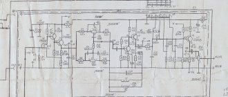
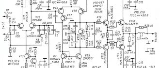
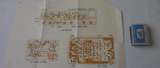
Some of the text has already been published on the forum, so repetitions are possible, but there are also changes. I will step by step consider what, in general, needs to be done so that Vega can be called an amplifier. Skipping any stage will significantly affect the worse in any case, so if you can’t do it, it’s better to throw it away right away and not torment the poor device, it has already suffered a lot in its life. And so is the voltage amplifier, final amplifier and power supply. (At the end of the article there is a link to a high-quality archive of the circuit.)
A little about the company
The Soviet radio electronics manufacturer Vega was located in the city of Berdsk in the Russian Federation. In principle, the plant still exists, but things are going very badly for it. But that's not the point. Previously . It was engaged in the production of household radio electronics: amplifiers, cassette decks, vinyl record players, speaker systems. A little later, the plant began producing CD players. Until the 90s of the last century, Vega software products were in almost every home. Her amplifiers were wildly successful. Our hero, “Vega 50U-122S” (amplifier), is no exception. However, after 1997, the plant’s strong position began to shake. And at the beginning of the 2000s, the company was declared bankrupt and disaggregated.
Today, Vega Software is engaged in the repair of household radio electronics and the production of devices for special orders. There is no trace left of its former greatness. Now legendary amplifiers and speakers can only be found on the secondary market. But their condition will, of course, be far from new. Nevertheless, the memory of high-quality speaker systems turned out to be surprisingly tenacious. Many music lovers are still looking for the legendary Vega 50U-122S (amplifier) at flea markets. Why is this device so attractive to audiophiles? Let's try to figure it out.
↑ Power supply
First of all, you need to deal with the amplifier's power supply circuit, it's just quiet horror.
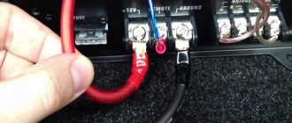
Thin wires to the transformer, capacitors, and power circuits are routed across the entire board from the rectifier, which is designed in such a way that the main advantage of the amplifier circuit—dual power supply—is negated. We change all the wires (increase the cross-section) that are marked in red in the diagram, for plus and minus capacitors - at least 2.5 mm², for the total I have 6 mm², for the transformer and speakers 1.5 mm², twisted together, output from the headphone scarf also with twisted wires 1.5 mm², each pigtail for its own channel. In addition, on the board the power circuits must be connected (duplicated) directly to the outputs of the rectifiers; for this I used copper 100-amp buses, but it is even better to do this with acoustic wires.
Take good capacitors in the rectifier (the bass and lower mids depend on their quality), with terminals on rivets, no Chinese consumer goods with wire terminals, each capacitor must be shunted with a film (I have polypropylene EPCOS 63 V 1 uF) (the average and high frequencies). Special fanatics can also change the diodes in the bridges to Schottky type KD2998G (the anode-cathode is completely suitable in size and location, but operates at the limit of the reverse voltage), this will help squeeze out a little more power, I don’t know how much, I haven’t changed it)
The only justification for connecting 23 and 33 volt sources is the absence of high-voltage capacitors. We decouple them and get 2 independent sources - 23 for the power and 33 volts for the preliminary part of the amplifier, this immediately affects the sound, and now the power drawdown from the 23-volt source does not affect the preliminary stages in any way, and the current from the 33-volt source is only taken at the very peaks of the signal (by the way, a common mistake is to interpret the operation of the output stage of the Vega, or rather its voltage boost - it actually works like this - when the amplitude value of the output voltage turns out to be greater than the supply voltage ± 23 volts (or whatever remains there)), only at these moments, the boost transistors open and pull the supply voltage up to the amplitude at the output.
By the way, this circuit practically does not work on Vega (and on the unfinished Vega it does not work at all, again due to the connection between the high-voltage source and the low-voltage source and the drawdown in both of them due to this), so that it works without distortion and opens the voltage boost transistors earlier than the limitation occurs at the output, it is necessary to reduce the resistance of resistors R37, R39. Replacing resistors R103, R105 in the pre-output stages is necessary in order to increase stability and limit current peaks through transistors VT27, VT29 (previously they were about 4 Amperes, which is why these transistors burned). It is also necessary to replace all small ceramic capacitors with a capacitance of picofarads with normal groups of no more than M1500.
Join the discussion
You can post now and register later. If you have an account, log in to write on your behalf. Note: Your post will require moderator approval before it will be visible.
Related publications
I'll buy a resistor (volume control). 4-section, 250 kOhm, with loudness compensation, 16 pins. I will consider any suggestions.
Why is this even necessary?! A reasonable question. Sometimes it is necessary. Always when you need to connect one sound source, for example a subwoofer. Or, as in my case, the task was to voice an open-air dance event. I had a guitar amp in stock, into which I plugged the ZK-502T class D amplifier board on a TPA3116 and converted it to power it from a lithium battery. And everything was fine, but it could only play one channel, since there was only one speaker. In fact, there are more than one questions and solutions. But we’ll skip them and go straight to the technique.
The board has a TPA3116 class D amplifier, a microprocessor with a DAC, ADC, MUX, USB and bluetooth, high and low frequency adjustment. This is not at all high-end, it has shortcomings, but for our purposes it is what we need. The problem is that the output stages of active devices in an analog circuit usually have low impedance and it is impossible to simply short-circuit the right and left channels. At best, the device will be protected; at worst, it will burn out. There are different ways to solve this problem. Let's look at two of them: resistor-based adder operational amplifier adder Resistor-based adder Probably the simplest method. We take 3 resistors and solder them according to the circuit directly to the input of the amp. Then we feed it to one of the channels of the amplifier board and that’s it. The simplest analog signal adder
↑ Where did the dog rummage?
A complete run of the amplifier circuit in the simulator, including the voltage and current amplifier of one channel, led to the conclusion that the main distortions at power close to the maximum arise from the imbalance of the input part (there is no other way to call it) of the current amplifier.
Moreover, distortion occurs in the voltage amplifier, and not in the op-amp for correcting the distortion of the terminal (as is known, op-amps have a level of suppression of power supply noise and common-mode interference of the order of 80-100 dB and higher, so power imbalance even by a few volts does not lead to significant distortion). A voltage amplifier (VA) disconnected from the current amplifier produces at the output about 0.005% harmonics at 10 kHz (with an output amplitude of 30 volts), when connecting an end cap, even with full balancing, the distortion of the VA increases by an order of magnitude (0.05%) (at 1 kHz these parameters are respectively 0.002 and 0.006, so don’t be alarmed. That is, we need to make the life of the UA, first of all, easier in order to get high-quality sound and high-quality transmission of the signal from its output to the input of the power amplifier.
This is done in several ways. First - we change the most terrible thing for sound - electrolytic capacitors with decent ones, and the same and the best ones you have, the larger the capacitance the better, I used 105 degree 1500 microns at 16V, from Sanyo, from a failed motherboard (I don’t recommend using solid-state capacitors from new motherboards for sound, and I also recommend getting rid of old high-quality motherboards, otherwise you won’t find decent capacitors anywhere for almost nothing). You can, of course, install Black Gate, but it will cost more than the entire amplifier. Now attention is a MUST! shunt them with polypropylene film (EPCOS), at least 1 micron, and preferably more (the more, the better the mids will pass), for each, the ENTIRE sound of the amplifier in the upper middle and high frequencies will depend on this. By the way, I initially tried to listen without them, having heard about the good frequency properties of computer capacitors, I was unsatisfied - the same tightness and dirt on the HF, can only be removed by shunting them with film (for a long time I could not understand what is wrong with the sound when the output of the film capacitor is in one arm fell off), don't neglect it.
Secondly, we remove all nonlinear elements from the input, that is, zener diodes and diodes in the power arms (I don’t understand why the diodes were installed there, there were probably extra ones in the warehouse)). This step is no less important, despite some concerns about the work of the OU. Removing the zener diodes will greatly improve the sound in the lower mids, very much. We can say after this that the amplifier will finally sound as high-class equipment should sound, which is what I didn’t like about its operation. Hoarseness and tightness in the mid frequencies will go away and a lightness and openness of sound will appear on them. And all because the capacitors are not ideal, and part of the input signal still passed through the zener diodes, they spoiled the whole sound. To set the op-amp supply voltage within 12-15 Volts, we increase the resistance of the resistors in the arms to 2.4KOhm (in addition, this will have a positive effect on the unloading of the voltage amplifier, distortion at high frequencies will drop by about 2 times), do not be afraid of the lack of zener diodes - the voltage itself is fine balanced (unbalance no more than 0.5-1 volt) and filtered from low-frequency interference by powering the interference with the same 1500 micron capacitors.
We change the op amp to KR574UD1 (budget option). And this is an absolutely correct choice, I must say!) I listened to NE5532 and NJM4580 in its place (horror, now I understand)) - clean, smoothed out and dead, details are lost, not at all impressive. Just be sure to check that there is no excitation at the op-amp output. By default (with a simple replacement at the factory, at factory values) it is at a frequency of approximately 10 MHz. It is inaudible and has virtually no effect on the operation of the amplifier, except that it kills the sound. To exclude this, we set the values and additional capacitors according to the diagram. Capacitor C23 eliminates HF excitation, the RC circuit eliminates HF oscillations on the pulse signal. After installing this correction circuit, it became possible to listen to the AD8066 and LM4562. I didn’t really like the LM4562, although this sound will also find fans, it’s too smooth, but at the same time clear, with it you can hear the background, but, I think, due to the slightly suppressed highs. AD8066, dual, (single amp is a direct candidate for replacement, suitable for pinout and board is AD8065) I really liked it, excellent sound, excellent transmission of high and mid frequencies and without distortion, it’s fascinating, although it can be too bright, you can also get tired of this) .
The KR574UD1 is located approximately in the middle between them in terms of sound color, closer to AD, but loses to both in terms of sound purity and lack of distortion, but it wins back its price of 25 rubles versus 150 for the AD8065 by 200%). Although I will say that after hearing AD I will not return to 574. As a result of this research, I have an AD8065 in my terminal. Since their quiescent current is quite high compared to the 574 series, there is no need to change the resistance of R29, R31; the op-amp supply voltage at factory ratings is ±12 Volts. As another option for a possible replacement, I recommend paying attention to the AD8671 - this is an excellent low-noise, high-linearity op-amp with amazing reproduction of musical instruments, especially good for classical music. I will say that I regret a little that I heard his sound later than I listened to the Vega, otherwise he would probably have stood in it.. But this is the topic of another article.. Maybe someone will try).
Next, there is another circuit that spoils the sound and by eliminating which you can gain some more improvements in the sound - this is the RL circuit at the output of the amplifier. In practice, it is installed to increase stability on a capacitive load and eliminate RF excitation under possible circumstances. If everything is fine with this, or rather nothing like this is observed, feel free to short-circuit this chain. This increases the rate of rise of the output voltage and reduces the loop force OOC (and distortion, respectively) for the op-amp in the case of its correction based on the maximum coincidence of the input and output signal of the amplifier (for me this correction is provided by that same additional RC chain and its ratings are given specifically for the amplifier version without output RL circuit, when switched on in this way, ensuring the absence of any surges or blocking of the meander fronts at the load). Only then you need to be very careful in connecting the output terminals of the amplifier to the measuring equipment (for example, when I accidentally connected the signal output to the common probe of the oscilloscope, a terrible excitation of the RF tip began). On a real load in the form of an AC there is no excitation, and there are also no parasitic emissions on the meander.
Another subtlety regarding connecting the load. There were several versions of the Vega, one (I have one) implemented the ITUN mode (see resistors at the ac output), it should be excluded for the sake of normal bass, and not rollicking boom (as was the case with my Vega and many even boast about it)), if Of course you are not going to listen to the classics. If you are going to do so, run the feedback wires from the board with high-quality shielded resistors (the screen is grounded from the end of the speaker) straight to the UA, bypassing the headphone board and the power amplifier board.
Now our amplifier is already half ready and to keep it that way, it remains to reveal a terrible secret - why does it burn out for no reason? The answer is simple: thermal stabilization. More precisely, its absence. Having carefully looked at the diagram, and then at the physical installation, we see that the quiescent current setting transistor VT17 does not in any way contact the output transistors, which sets the quiescent current. But for some reason it is connected to VT27 (pressed to its radiator)... Apparently the engineers had the hope that at least in this way the quiescent current would not flow as it wanted. They hoped in vain. We are correcting this annoying stupidity that cost the lives of most of the buried Vega.
Don't forget the insulating gaskets for the transistors. In addition, it is necessary to replace the tuning resistors R51, R52 with decent ones, preferably ceramics, since with the ones I had I could not establish a stable quiescent current, any blow to the case led to its change. And only after this you can try to adjust the quiescent current of the final transistors themselves.
In the simulator, the minimum quiescent current ensuring low distortion was equal to 80 mA and higher. I tuned it based on the absence of blocking of the meander fronts at 20 KHz and the absence of distortion of the triangular signal of the same frequency. I did not measure the quiescent current itself after this - this is quite problematic due to the circuit design, but judging by the constant heating of the radiator of the output transistors to 45 - 50 degrees, the current turned out to be somewhat higher. But you shouldn’t be afraid of this, the introduced thermal stabilization perfectly maintains it at a constant level, whereas without it, with such a quiescent current, the amplifier would overheat and fail even in the absence of a signal.
Re: Repair Vega 50u-122s
I'll look for the diagram. I am guided by the input switching board. it is on two kr1334ud1b, one kr590kn3 and one k561ir9
———- Message added 18.21 ———- Previous message was 14.59 ———-
I found a circuit, only in poor quality (((but it is more suitable for the circuit design of my version of the amplifier (input board).
———- Message added 21.26 ———- Previous message was 18.21 ———-
Now I'm playing with the inputs. Everything is silent, except for the pickup. On it, at the highest volume, a crackling sound comes through, well, like a signal, not continuous. Where to look next? who should I change? and also, here the previous owner also damaged the Kuts-1m relay, is it really possible to find them now?
———- Message added 22.24 ———- Previous message was 21.26 ———-
The voltages are fine (range 1-1.5 volts). at the output of the ac terminals on one channel -0.5v on the other +0.5v. volume knob at zero.
Source
↑ Next - to the entrance
The UN is assembled according to the classical scheme and does not require any modifications at all.
We change C6 to a good one and bypass it. Since it is only 0.6 Volts, you can do without it at all, but replacing it with a jumper had a negative effect on the sound (although it did not spoil it terribly), so it was decided to leave it, if we leave it, then it is necessary to change the polarity to the opposite one, in both channels with When I measured the voltage on C6 with a multimeter, it turned out to be the opposite polarity than on the amplifier circuit (although it wouldn’t hurt to check just in case). C1 is naturally MKP, although if you want all your efforts to be in vain, you can leave this ceramics or the K73 that was there from the factory. (and in one channel I had a ceramic one, in the other K73))) After all these measures on sound quality, the power amplifier will be at such a level that the influence of the wires used to connect to the source and the speaker has now become audible, and this already means a lot. The bass after modifications to the power supply will amaze you, and the heatsink of powerful transistors practically stopped heating, even with a significant output power (probably the developers of the case, leaving such small slits for cooling, thought that the designers of the printed circuit board and connections would provide an efficiency equal to the calculated theoretical one).
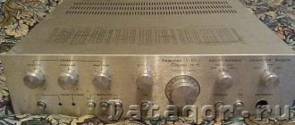
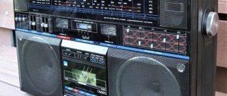
Appearance and Design
Let's start with the appearance of this amplifier, because it is too early to move on to the technical characteristics. Typically, Soviet devices were heavy and bulky. It’s better to remain silent about design altogether. But the Vega 50U-122S sound amplifier is completely different. It has an incredibly thin body (for Soviet equipment). Most of all, it resembles a Chinese DVD player. This design made it highly desirable for many music lovers. However, despite the thin body and not too large dimensions, the amplifier weighs a lot. His weight is more than five kilograms. For a stationary device this is quite normal. However, taking it anywhere with you will be problematic.
The second design feature is the playback device switch buttons. They are quasi-sensory. This means that there will be no usual click (as in other Soviet amplifiers). They press softly and easily. An unprecedented achievement for domestic technology of the 80-90s. “Vega 50U-122S” (amplifier), the technical characteristics of which we will discuss a little later, can be considered the most stylish device in the post-Soviet space. Although in terms of sound quality it may be inferior to other more famous brands. But we will talk about this further.
↑ Now the entrance part is no less problematic.
You can start with a simple thing - we short-circuit all the electrolytes with jumpers, remove the equalizing potential resistors that have become unnecessary. This is all unnecessary. Next, we unsolder DA2 (K157UD2), throw it into a bucket, and put jumpers in its place. The most unpleasant thing remains - the volume control, or rather, the fact that it should be low-impedance. The variable resistor for it is from 1 but not more than 5 Kohm (preferably lower). Everything else will not work, it will sound very, very bad and depend on the position of the volume control (tested at 22KΩ) due to the fact that the resistance of the UN in the UMZCH is about 10KΩ. Since I couldn’t find a variable dual resistor SP3-33 for such a resistance, and even with characteristic B, I had to make one out of two single characteristics A, one double and bypass its motor with a resistor equal to 1/3 of the resistance to obtain a characteristic close to B. The same This option sounds very decent, and also has a low output impedance throughout the entire adjustment range. You can listen to the import, but I haven't tried it. Next, we turn off the thermistor circuit and unsolder the extra wires that are crossed out (required!). Everything is finished on this board.
The input switch board will require more intervention. First, you need to replace the DA3 op-amp with LM4562, as it provides the most neutral sound, invisibility in the path and ultra-low Kg. Since we have lost one amplification stage, this responsibility now falls to her.
We add resistors that turn the repeater into a non-inverting amplifier with Ku = 9.3. In this case, the input sensitivity of the entire amplifier will be about 500 mV. This signal level should not be significantly exceeded, since for the LM4562, after an output voltage greater than 6 Volts, Kg increases significantly (that’s why its supply voltage was chosen as high as possible - about 16.5-17 Volts (particularly attentive ones can find my modest assumption in the circuit ;)) . This option is suitable for playback from a computer sound card, but not from a CD player. In this case, there are additional resistors connected in parallel to the main ones, reducing the gain to 2.9 and providing a sensitivity of 1.5 volts.
As unnecessary, we replace the separation capacitors C9, C10 at the input of the op-amp with anti-ringing resistors, R9, R10 are also excluded. The nutrition of this part is important. It needs to be separated from the digital one and make your own stabilizer, as you can see here it is assembled using composite transistors according to a simple circuit, but it provides excellent sound. The main thing is that the zener diodes must be domestic in a metal case, imported glass ones will not work, the parameters are too poor and the sound with them is bad. Then 2 rolls are better. The common wires of the digital and analog parts on the board are already separated, this is probably the only thing that was done correctly.
The switch on the KR590KN3 in this case will be the weak link limiting the fidelity of the sound. I still have it in place, only now as a switch for high-impedance 24 volt relays RES-49, and they already switch signal circuits. For the PCD input, 2 more relays in the preamplifier are switched on, reducing sensitivity. Since the current of the microcircuit is not enough to control 4 relays at once, it’s time to turn them on through a transistor repeater.
Again, we remove all the connections that are crossed out on the diagram, the sound quality depends on this.
What remains is the entrance part. It seems like nothing complicated, but even here the veggie engineers made a complete mess. Starting from the fact that the common wire on all sockets is combined, it is also connected in that place to the amplifier body, and it goes to the board haphazardly and along different wires at the same time with an unshielded cable and along the cable braid for the pickup corrector. Moreover, this greatly affects the sound and different channels in different ways (even before all the modifications, I heard that the right channel sounds much better, after-sounds are audible, but this was not the case in the left channels.. I blamed the circuit, the op-amps, but not the wires, what was it like? surprise, having done all this, the problem remained, only manifested itself more strongly - the right one sounded much better through the input jacks. And that simply pulling the cartridge equalizer cable out of the jack equalized the channels...)
In general, we do it right - we separate each input with its own common wire, cut the printed circuit on the input connector board and also separate each connector from each other. We pull the cable that goes to the switch board into separate conductors, bite off the excess ones, and twist the remaining channels according to the pigtail principle, each to its own channel. You can also put a shielding braid on top and ground it on the signal side, but I didn’t do this (probably in vain). Be sure to make sure that the signal cable is not grounded anywhere on the amplifier body (this is at the pickup input). Now it will sound.
General view from below
above
Additional options
What else can the Vega 50U-122S amplifier boast of? Its characteristics are far from the main thing. The most interesting thing is the additional features of this model. These include excellent protection against voltage surges and overloads. If the voltage reaches a critical level, the amplifier automatically turns off. So it is completely protected from burnout. There is also an option to automatically turn off if there is no sound signal from the source for a long time. This helps save energy. Thus, this amplifier can be called unique. Especially compared to other products coming from the Soviet Union.
What else is characteristic of Vega 50U-122S? The amplifier is equipped with a four-band equalizer. It helps make the sound better. It is possible to force the device to work in mono mode. But this is not the main thing. Much more interesting is the ability to connect additional acoustics. In addition to the main pair of contacts for connecting speakers, there is one more. With this type of connection, it is quite possible to achieve surround stereo sound using four different speakers. Not all amplifiers of this class have such a useful option. This alone makes Vega a very interesting device.
↑ Tests
Testing was carried out using a Creative Audigy 4 sound card in Loop mode using RMAA 5.5.
The op amp at the card output was replaced with AD826. Vega input - tape recorder 1, sensitivity 500mV, output 2 load wire resistors with a resistance of 5.6 Ohms with a divider providing a nominal signal at the input of the sound card. A little about empirical units - 0db - 22v 43w -10db - 7v 4.37w -20db - 2.2v 0.43w As can be seen on the 5.6 Ohm resistor, it can now produce an amplitude value of 22 volts, a power of 43 W per channel, and were tested immediately 2 channels. Not bad, 86 honest watts from such an amplifier, although at peak it will give more than 100 watts.
The results of all tests are in a summary table.
Below are the test graphs of the sound card itself.
Harmonic distortion 1KHz
Intermodulation between 1KHz and 7KHz frequencies
And accordingly, the results of testing the amplifier itself at different output signal levels.
Harmonic distortion 1KHz at -20dB
Harmonic distortion 1KHz at -10dB
Harmonic distortion 1KHz at 0dB
Intermodulation between frequencies 1KHz and 7KHz at -20dB
Intermodulation between frequencies 1KHz and 7KHz at -10dB
Intermodulation between frequencies 1KHz and 7KHz at 0dB level
Changes in the output level were made by the volume control of the amplifier itself; all sound card settings remained unchanged.
I would like to draw your attention to the fact that Kg and Intermodulation distortion weakly depend on the output power (although of course everything is much more clear on the graphs), that is, the amplifier stages almost always operate in optimal modes and it is possible to squeeze out something else from them in the existing element base and circuit design does not seem possible.
In addition, measurements were carried out with the high-pass filter, low-pass filter, weakened midrange and equalizer turned on, the results may also be of interest. Placed in a pivot table.
Frequency response graphs for various modes.
EQ noise and Kg are clearly depicted in the following visualization.
It is clear that it can only be used at some kind of party, when there is little bass, for example)
Also, Vega was once tested (though for a real load in the form of AC) without any modifications, except perhaps with the KR544UD1 replaced by KR574UD1, the measurement results were preserved, which I present in the table and visual graph.
As you can see, the tabular parameters of the previous vega are not too worse, the graph is much more terrible. Which once again proves that the numbers practically do not reflect the real quality of the equipment.
I will also give 2 more oscillograms - a rectangular and triangular signal with a frequency of 20 KHz measured on an active load.
When connected, the speakers remain virtually unchanged. However, connecting a capacitor of about 2 μF to the output of the amplifier already leads to self-excitation at high frequencies. This also needs to be remembered. The amplifier bandwidth on a sinusoidal signal at a level of 3 dB turned out to be approximately equal to 500 kHz.
Technical description
The model was based on the previous version 120. The tape drive mechanism migrated from there. The display unit has been improved. A speed of 9.53 cm/s was added.
“Vega MP-122S” itself becomes a base. It was on its basis that the Vega TM-122S cash receiver was created, where the second tape drive replaced the FM tuner with 8 stations.
Modes implemented in Vega MP-122:
- Play and record audio cassettes at two speeds.
- Search for a recording by pause between songs.
- Sequential playback of the second cassette after the first.
- Cassette review.
- Rewind to the beginning of the tape and then play automatically.
- Memory, that is, the device can remember a point on a cassette.
- Synchronous rewriting.
- Record a pause.
These functions make this tape recorder unique in terms of ease of use, which had no equal in the USSR.
Technical features:
- Compander noise reduction system.
- Possibility to choose between two settings: Fe and Cr for the corresponding cassette types.
- There is a headphone jack with volume control: the right and left channels are separate from each other.
- When recording and re-recording, it is possible to adjust the input signal level: the right and left channels separately from each other.
- Signal level indicator for the right and left channels: red or red-green.
- The Vega MP-122 tape recorder, like its other peers, had a pocket light. It allowed you to see how much tape was left.
- Pseudo-sensory control.
- Three-motor tape transport mechanism. He allowed us not to use belts.
- "Versatile, wear-resistant sandust head."
- Electronic tape counter.
- LED indication of modes.
↑ Files
Additionally, I am attaching files of all measurements in the archive