The author of the circuit of this amplifier, A.I. Manakov, has been designing high-quality sound-reproducing equipment since 1963. In my opinion, he succeeded a lot in this. His designs have an excellent sound, are easily repeatable and have a well-deserved success even among beginners. I will only (with the permission of the author) outline the features of his work.
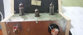
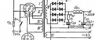
Readers are offered a simple original power amplifier circuit in two versions. The first is a budget one, with automatic biasing of the output lamp. The second is with a fixed bias from a separate winding of the power transformer.
According to the author of the circuit, the version with a fixed offset has a deeper and more beautiful sound, although the option with an automatic offset will not disappoint you, allowing everyone who repeated it not to recognize the sound of their favorite recordings.
6P43P in high load mode
6P43P in high load mode. At the request of one of the radio amateurs, I had the opportunity to select sets of 6P43P-E lamps for a Komarov push-pull amplifier, designated as a student course project. A normal commercial project for me is to select the ideal pairs of output lamps for money. However, for me this is a typical example of marketing promotion of specific types of lamps. I have devoted many articles to the stupidity of subordinating people to marketing and the harmfulness of such an approach. I have said it many times and I will repeat it again, it makes no sense to start from the types of lamps. Lamps can be anything. It is much more important to decide on the output transformer for a specific acoustic system. And then, select lamps for the finished transformer. I will clarify the conflict of interests that arises during the selection of an amplifier further. The fact is that the power of the selected amplifier is small, about 10 W. A normal lamp starts at 25 W. Therefore, the temptation immediately arises to connect the output lamps in parallel, which is easy to do in such a circuit. But then the question arises about the quality of the amplifier design with a single output transformer of armored design. I think people’s complaints about such a release are quite fair. Well, single standard transformers do not sound in Hi-end mode. Trance does not sound at all in such a scheme. But then there is a need to select a differential output pair or get involved in winding procedures. Well, what does this have to do with the initially chosen scheme from a student’s course project? And what do 6P43P lamps have to do with it?!
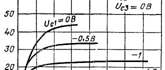
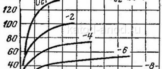
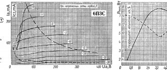
During a commercial study of 6P43P lamps, we had to measure about 80 pieces from stocks from the 70s. It turned out that most of the lamps were naturally drooping due to their low slope value. After training on the L1-3 lamp meter, most of the lamps were within the datasheet. About 10% was thrown into the trash. To study the characteristics, a 6P43P punched card from the standard set was used. In assessing the real properties of lamps when the nominal mode is exceeded, it was necessary to expand the scope of experiments. Some difficulty in using a lamp meter and standard cards is the lack of ability to control the displacement of finger pentodes along the grid. Therefore, in order to increase the anode currents, it was necessary to use a card from 6P14P, and then 6P15P. A 340 Ohm resistor is installed in the 6P43P cathode auto-bias circuit. For a 6P14P lamp the resistance is already 120 Ohms, and for a 6P15P it is only 75 Ohms. Reducing the cathode resistance makes it possible to extract significantly higher currents from the anodes. In this case, during the experiment, you should carefully monitor the anode current, excluding self-heating and overload by quickly turning off the power. Pictures for the cards are shown below.
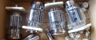
For the experiments, dead lamps were used, with minimum current and slope parameters according to the datasheet: 36 mA and 6 mA/V. As it turned out, the use of a card for 6P14P allows one to increase the anode current to 57 mA, while maintaining long-term thermal stability. The voltage of the second grid is limited by the regulator at 140 volts. It was possible to raise the anode voltage up to 280 volts, the calculated power being 15.96 W. There were no signs of anode overload, but the glass container became very hot. Next, a 6P15P card was used, and the current was increased to 72 mA, almost to the maximum value on the lamp meter scale (Fig. on the left). At the same time, the current protection of the lamp meter began to operate. The anode voltage had to be lowered to 240 volts so that the protection would not turn off the meter. Again, no signs of reddening were observed in the anode, although the calculated power value increased to 17.28 W. An example is shown in the picture below. Confirmation of the use of a 6P43P light bulb with a 6P15P card is shown in the photo on the right, where the shape of the anode is visible.
Slope was assessed periodically throughout the study. At the same time, it was discovered that all frail specimens of 6P43P, under extreme loading and such a significant increase in current, were unable to provide a significant increase in steepness. In the experiment with dead animals, it was not possible to obtain S values greater than 5 mA/V (center figure). But for working specimens, the steepness jumped as significantly as the anode current. For example, for several known-good copies, values of S = 9 ... 10 mA/V were obtained, with initially measured values of about 8 mA/V. The following obvious considerations can be formulated as conclusions.
1. Dead pieces of glass and lamps with signs of old age at the lower edge of the datasheet should not be used in the designs of high-quality amplifiers with high power-to-weight ratios. Rejection of stored specimens should be carried out precisely according to the boundary parameters, ruthlessly disposing of lamps with insufficient anode current and low slope. In dynamics, the margin should be both in current and in transconductance.
2. Taking into account the significant power reserve in the anodes of the output pentodes, it is possible to allow some overload of the lamps. However, it is preferable to increase the voltage and not get carried away by excessively increasing the current. The power release in the anodes in dynamics, while maintaining thermal stability, can be very significant, comparable to the power released in the anodes in static conditions.
3. Automatic bias circuits with cathode resistors should be considered very, very useful for insurance against extreme currents. Therefore, the loss of power in cathode circuits and additional heating should be tolerated. The best percentage of automatic and fixed offset is the subject of a separate study.
4. The high load mode cannot be perceived as the normal state of the lamp in the amplifier. This is a test mode to train the lamp. Its importance should also not be overestimated. Reanimating old lamps is a thankless task. Sometimes it is possible to revive old items, but vintage or worn-out products can no longer work intensively.
Evgeny Bortnik, Krasnoyarsk, Russia, May 2018
Radio tube 6P43PE
The directory of precious metal content in radio components was created on the basis of reference data from various organizations involved in the processing of scrap radio components, device passports, forms and other open sources. It is worth noting that the actual content may differ by 20-30% downwards.
Content
Content of precious metals in the radio tube: 6P43PE
Gold: 0.001514 Silver: 0 Platinum: 0 MPG: 0 According to: Roscosmos list
What precious metals are contained in radio tubes
Radio tubes can contain gold, silver, platinum and PGMs (Platinum group metals, Platinum group, Platinum metals, Platinoids, PGE). Precious metals are mainly found in lamp grids or as coatings.
An electron tube or radio tube is an electric vacuum device (more precisely, a vacuum electronic device) that works by controlling the intensity of the flow of electrons moving in a vacuum or rarefied gas between the electrodes.
Main types of electronic vacuum tubes:
Diodes (easily made for high voltages, see kenotron) Triodes Tetrodes Pentodes and Beam tetrodes Beam pentodes (as a variation of this type) Hexodes Heptodes (pentagrids, five-grid) Octodes Nonodes Combination lamps (actually include 2 or more lamps in one cylinder) Discharge lamps
Designation system for lamps produced in the USSR
The first part of the marking is a number indicating the rounded value of the filament voltage (for receiving and amplifier lamps): 06 - 625 mV 1 - 800 mV, 1 V, 1.2 V, 1.4 V, 1.5 V 2 - 2 V, 2.2 V, 2.4 V 3 — 3.15 V 4 — 4 V, 4.2 V, 4.4 V 5 — 5 V 6 — 6 V, 6.3 V 7 — 7 V 9 — 9 V 10 — 10 V 12 — 12 V, 12.6 V 13 — 13 V 17 — 17 V 18 — 18 V 20 — 20 V 25 — 25.2 V 30 — 30 V
Generator tubes, barretters and zener diodes have a letter index indicating the type of lamp: GI - Pulse generator tube GM - Modulating tube GMI - Pulse modulation tube G - Generator tube (for older lamps) GK - Generator HF lamp (for frequencies up to 30 MHz ) GU - (For example, GU-50 Generator VHF lamp (for frequencies up to 300 MHz) GS - Generator microwave lamp (for frequencies above 300 MHz) GP - Regulating lamp GPI - Regulating pulse lamp SG - Gas-filled voltage stabilizer (zener diode) ST - Gas-filled current stabilizer (baretter)
The second part of the marking is a letter (or two letters) of the Russian alphabet, indicating the type of electrode system of the lamp (for receiving and amplifier lamps): A - Frequency-conversion lamps (hexode, heptode) B - Diode-pentode, double diode-pentode (combined lamp) C — Lamp with secondary emission G — Diode-triode, double diode-triode, triple diode-triode (combined lamp) D — Single diode (except for rectifier kenotron) E — Electron-light indicator G — High-frequency pentode with a short characteristic I — Triode- heptode or triode-hexode (combined lamp) K - High-frequency pentode with an extended characteristic ("varimu") L - Beam lamp (except for the beam tetrode) M - Double pentode (only one lamp of this type was produced - 12M1M) N - Double triode P - Output pentode or beam tetrode P - Double tetrode, double beam tetrode or double pentode C - Triode T - Thyratron with a cold cathode (only one thyratron was produced with the designation adopted for receiving and amplifying tubes - 1T1A) F - Triode-pentode (combined tube ), exception - pentode of the old production 6F6S X - Double diode (except for kenotrons) C - Rectifier diode (kenotron) of any type E - Tetrode SR - Double pentode-triode
For cathode ray devices: LI - Transmitting tube LC - Kinescope with electromagnetic beam deflection LM - Oscillographic tube with electromagnetic beam deflection LN - Storage tube LNS - Character-printing storage tube LO - Oscilloscope tube or kinescope with electrostatic beam deflection LP - Cathode-ray switch LS - Character-printing tube LF - Functional tube
The third part of the marking. For generator and receiving-amplifier tubes, picture tubes and oscilloscope tubes there is a number indicating the development number. For zener diodes and barretters it is the same as the 4th element for receiving and amplifying tubes.
The fourth part of the marking. It is absent for zener diodes and barretters. For picture tubes and oscilloscope tubes, it can indicate the type of phosphor used for the screen. For receiving and amplifying lamps - a letter indicating the design of the lamp: A - Subminiature glass cylinder with a diameter of 5-8 mm with flexible wire leads B - Subminiature glass cylinder with a diameter of 8-10.2 mm with flexible wire leads D - Miniature glass cylinder with a diameter of more than 10.2 mm with flexible wire leads D - Ceramic cylinder with disk leads ("beacon" lamps) F - Acorn-type lamp - a miniature glass cylinder with rigid radial leads. K - Ceramic cylinder with pin leads. L - Lamp with an octal base equipped with a lock, which prevents the lamp from falling out of the panel when shaking (“octal”). The cylinder is glass, covered on the outside with an aluminum casing. M - Small-sized glass cylinder with an octal base of reduced height (“malgab”). The letter is retained only for some lamps of older releases (2K2M, 2Zh2M, 2P9M, 30Ts1M, etc.). N - Nuvistor (miniature lamp in a metal-ceramic cylinder). P - Miniature (“finger”) lamp — a glass cylinder with a diameter of up to 22 mm with seven (“heptal”) or nine (“noval”) rigid leads soldered directly into the bottom. C - Large glass cylinder with a diameter of more than 22.5 mm or a metal-ceramic cylinder, including one with an octal base. P - Subminiature glass cylinder with a diameter of less than 5 mm with flexible wire leads. The only lamp produced in this design was 1Zh25R) No letter - Metal (usually steel) cylinder with an octal base
For generator lamps - a letter indicating the type of cooling: A - Forced liquid, water or air-water B - Forced air K - Contact P - Evaporative No letter - Natural air
The fifth part of the marking characterizes the special properties of the lamps. Optional, always placed with a hyphen, applicable only to receiving and amplifying lamps. B - Lamp of increased mechanical strength and reliability E - Lamp of increased durability (5000 hours or more) D - Lamp of particularly high durability (10,000 hours or more) I - Lamp designed to operate in pulsed mode K - Lamp of increased mechanical strength and reliability with increased vibration resistance P - Lamp of increased mechanical strength and reliability, with increased radiation resistance (better than B; however, to replace a group B lamp, both P and B must be present in the designation)
Share link:
Liked this:
Like
