Closed speaker systems have become very widespread in recent years, which until recently were the only type of speakers for high-quality playback both in our country and abroad. And only in recent years, speakers with a bass reflex (AS with FI) and speakers with a passive radiator (AS with PI) have broken the monopoly of closed speakers.
Nevertheless, the acoustic design of a closed box is currently one of the most common designs of high-quality speakers in Western Europe and is quite widely produced in the USA, as can be seen from the table (data from 1984):
| A country | Closed systems, % | Speakers with bass reflex, % | Speakers with passive radiator, % | Other systems, % |
| USA | 42,7 | 32,4 | 8,6 | 16,3 |
| Western European countries | 60,8 | 31,7 | 6,5 | 1,0 |
| Japan | 27,9 | 62,3 | 9,8 | — |
In Fig. Figure 1 shows a typical closed speaker.
Tannoy TS2.8 active subwoofer in closed box acoustic design.
The advantage of a closed speaker is that the rear surface of the driver cone does not radiate and thus there is no “acoustic short circuit” at all.
The disadvantage of closed speakers is that the diffusers of their heads are loaded with additional elasticity of the air volume inside the design. The presence of additional elasticity leads to an increase in the resonant frequency of the moving system of the head in a closed design ω01 and, as a consequence, to a narrowing from below of the reproduced frequency range. The value of the additional elasticity of the air volume SВ can be found as:
SB=γp0S2eff/V, (1)
where γ is the adiabatic exponent, Seff is the effective area of the head diffuser, V is the internal volume of the design body.
The effective area of a diffuser is considered to be 50–60% of its structural area. For a round diffuser with a diameter d Seff=0.55S=0.44d2. This is equivalent to the effective diameter of the diffuser being 0.8 times the design diameter. The elasticity SВ is summed up with the self-elasticity of the suspension of the movable system of the head S0 and as a result the resonant frequency of the head in a closed design is calculated by the formula:
ω01=√((S0+SB)/m)=ω0√(1+SB/S0), (2)
where m is the mass of the movable system of the head.
As can be seen from formula 1, the elasticity of the air volume inside the design is inversely proportional to this volume. The elasticity of a moving system can also be expressed through the elasticity of a certain equivalent volume of air VE having elasticity S0. Hence the resonant frequency of the head in a closed design:
ω01=ω0√(1+VE/V) (3)
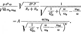
To ensure that the resonant frequency is not excessively high, heads with a heavier moving system are sometimes used, which makes it possible to slightly reduce the resonant frequency of the head in a closed design, as can be seen from formula 2. However, it should be borne in mind that increasing the mass of the moving system reduces the sensitivity acoustic system, as can be seen from the formula for standard sound pressure:
where A is a frequency-independent multiplier, Rr is the output resistance of the amplifier (oscillator), Rk is the active resistance of the voice coil, and is the effective radius of the head.
The so-called small-sized acoustic systems (MAC) have especially low efficiency, in which the elasticity of the volume inside the design is significantly greater than the elasticity of the fastening of the moving head system.
Such systems, in which the elasticity of the moving system is determined by the elasticity of the air volume inside the design, are called systems “with a compression suspension” of the head.
The standard sound pressure pst of such a system at frequencies ω>ω01, where pst is frequency-independent, is determined as follows:
rst=2.65*10-3√(f301V/Q01), (5)
where Q01 is the quality factor of the head in a closed design (measurement methods can be found in the article “Measuring Thiel-Small parameters at home”).
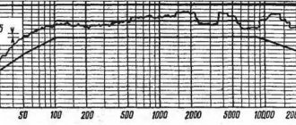
As follows from formula (4), the unevenness of the frequency response of closed acoustic systems in the low frequency region, just like open ones, is determined by the quality factor (Fig. 2).
Rice. 2. Frequency response of a closed system (AFC)
When Q01<0.707, the frequency response of the speaker decreases uniformly with decreasing frequency into the low-frequency region, and the unevenness manifests itself as a decrease at the resonant frequency ω01 compared to higher frequencies. At 0.70701<1, the frequency response has a small peak at frequency ω1 and then a decline at the resonant frequency ω01. The unevenness of the frequency response is determined by the rise at the peak ω1, and the decline at the resonant frequency ω01. When Q01>1, the unevenness of the frequency response is determined only by the face at frequency ω1 relative to the horizontal part of the response.
The unevenness of the frequency response depending on the quality factor of a closed speaker is shown in Fig. 3.
Rice. 3. Dependence of the unevenness of the frequency response of a closed acoustic system on Q01.
As follows from the figure, the minimum unevenness in the frequency response of closed speakers occurs at quality factor Q01=1 and is 1.3 dB. The desired quality factor of the head itself is determined from the condition:
Q=Q01/√(1+Veff/V) (6)
Studies have shown that the quality factor of heads intended for closed speakers should not exceed 0.8–1.
Otherwise, the head turns out to be “dedamped”. This means that when it is excited, i.e. when a music or speech program voltage is applied to it, the head, in addition to oscillating in time with the applied voltage, will also oscillate with a natural frequency close to the resonant frequency.
For listeners, this will manifest itself in the fact that the sound of this frequency will be mixed into the sound of the program as a kind of “hum”, “impurity” of low tones. Note also that if the head is placed in a closed box, the uniformity of the frequency response in the mid and high frequencies deteriorates due to resonant phenomena in the design.
To eliminate them, the internal surfaces (especially the back wall) are covered with sound-absorbing material and part of the volume is filled with it. In addition, by filling the internal volume with loose sound-absorbing material, another goal is pursued - to change the thermodynamic process of compression-expansion of air in the design.
Without filling, the process of compression and expansion of air inside the design is adiabatic. By filling the design with loose sound-absorbing material, you can change the adiabatic process to an isothermal one.
In this case, the internal volume of the design seems to increase by 1.4 times, since the coefficient γ in formula (1), which is 1.4 for the adiabatic, is replaced by a value equal to one for the isotherm. Accordingly, the resonant frequency of a closed speaker decreases.
This reduction in the limit (for a compression speaker) reaches √1.4, since for it the elasticity of the head suspension can be neglected. Otherwise, the resonant frequency of the head ω01' can be found as:
ω01'= ω01√((1+0.75 *S/S0) ∙ (1+S/S0)), (7)
Subwoofer box calculation
So, you have decided on a subwoofer, selected an amplifier for it, chosen an acoustic design and decided to make the enclosure yourself. Before creating a drawing, you need to calculate the box for the subwoofer, that is, obtain the initial data. For a closed box, this is the volume; for a bass reflex - this is the volume of the case, the cross-sectional area of the port and its length; for a quarter-wave resonator - the length and cross-sectional area of the tunnel; for bandpasses - the volume of compartments, the area and length of the ports, the shape of the case. All these parameters need to be calculated and special programs are used for this. The basis for all calculations are the Thiel-Small parameters.
The point of properly calculating a subwoofer is to design a design in which the speaker will produce bass that suits your tastes and musical preferences. For example, for a closed box, the smoothness of the frequency response and sound character will depend on the volume of the cabinet, which you will need to select based on the characteristics of your subwoofer speaker; for a bass reflex, the tuning frequency and the hump of the frequency response depend on the volume of the housing, the volume of the port, its length, shape and cross-section, etc.
Types of speaker systems
Sound is a vibration that has a mechanical origin, propagating under pressure caused by a radiation source. An acoustic system, which is a sound column, converts electrical signals into mechanical signals perceived by the human ear. The frequency of these oscillations ranges from 20 Hz to 20 kHz. There are different types of speaker systems:
- Acoustic labyrinth . It looks like a labyrinth, made in the form of a tunnel located in the middle of the column. Its purpose is to enhance low frequencies due to many bends. The internal walls of the labyrinth are covered with a damping coating, due to which the labyrinth does not introduce parasitic overtones into the sound.
Open type . It is a system in which a wall opposite to the direction of radiation from the speakers is not installed. In this type of performance it is impossible to get good low frequencies due to the lack of compression, and mid and high sounds seem more open and airy.- Closed type . It is made from a completely sealed housing, creating a closed volume of air inside. This volume forms internal pressure that interferes with the normal movement of the speaker cones. These types of speakers have large dimensions with an overlay on the inner walls - dampers. The advantage of this system is the purity of the sound, the range of which is not mixed with unwanted extraneous sounds.
- Isobaric type . It is difficult to manufacture and expensive, but due to its design features it allows you to increase the power and depth of the low-frequency component. In the middle of the speaker there are two speakers, separated by a soundproof partition and directed in one direction. These speakers are connected in parallel to each other and operate in phase.
- Passive . Its main purpose is to increase the efficiency of reproduction of the low-frequency component of sound through the use of a passive radiator. This emitter is located deep in the hole made in the speaker body and does not have a magnetic system. When a signal is applied, the emitter cone moves not by converting the electrical signal, but by the air flow caused by the installed woofer. This design allows for deep bass, but can introduce hum into the sound.
- With dipole emitter . Dipole-type acoustics reproduce sound in two directions. Another name for this type is bipolar. By its type it belongs to the open type. To obtain acceptable low frequencies, you will need to use speakers with large cones.
- Counter-aperture . Rarely used design. The speakers in it are directed to the upper or lower side, and the same signal is supplied to them. When the sound emitted by the speakers collides, it changes its direction, spreading radially. The disadvantages of such a system include the occurrence of reverberation, due to which the stereo panorama is “blurred”. The advantages lie in the appearance of the effect of “dissolving” sound vibrations in the room.
- Bass reflex . This system is made in the form of a classic closed-type column, but with a special hole. A pipe is installed in it, going deep into the box. This approach allows you to obtain low-frequency sound significantly lower in frequency than the capabilities of the speakers. Such a system is in great demand, as it allows one to reproduce deep bass in a relatively small body size, producing frequencies that are unattainable by simply using speakers.
The use of a bass reflex type makes it possible not only to expand the lower frequency range, but also to increase the efficiency. In this case, the frequency range will not change. The bass reflex hole comes in different types and sizes. It can be placed on any surface of the column. When developing an acoustic system, it is most important to correctly calculate the size of the bass reflex box, which determines not only the range of reproduced frequencies, but also the quality of the entire sound as a whole.
Programs for calculating the subwoofer enclosure
Speaker Box Lite
One of the most modern and convenient programs for calculating subwoofers. Speaker Box Lite will help you quickly and conveniently calculate the enclosure for the subwoofer, as well as draw its sketch and cut the material. It builds frequency response graphs, takes into account the transfer function of the cabin, is based on the Thiel-Small parameters, and additionally displays the system impedance, phase response, group delays, etc.
JBL speaker shop
A program for calculating the design of speakers and subwoofers in particular. The program is old and does not work with the latest operating systems, but nothing better has been invented so far, so you have to use small tricks to get it working. The program builds frequency response graphs, takes into account the transfer function of the cabin, takes into account the Thiel-Small parameters - that is, everything that is needed to correctly calculate the box for the subwoofer.
BassBox 6 Pro
The program for calculating subwoofers works on the basis of JBL speakershop, in the 5th version they even had the same interface - in the 6th it was changed. But the program works well and some may find it more convenient to work with it.
Bassport
A narrowly focused program designed to calculate bass reflex ports for a certain volume; it cannot fully calculate the enclosure . All attention is directed to the design of ports, taking into account air flows, shapes, distances to walls and partitions.
UniBox (Unified Box Model)
A very simple program that runs on Microsoft Windows Excel 2000 . Can simulate sound pressure level, speaker impedance curve, frequency response, etc.
What do you need to know before installing JBL SpeakerShop?
This program for calculating a subwoofer can only be installed on a computer with Windows OS. Unfortunately, it was released a long time ago, and therefore is only compatible with versions from XP and lower. To install on later versions of the system (Windows 7, 8, 10), you will need a special emulator that allows you to simulate XP.
Among the most popular and free programs that allow you to simulate earlier versions of Windows is Oracle Virtual Box. It is extremely simple and understandable. Only taking into account the above, and after carrying out preliminary manipulations, can you install the JBL SpeakerShop program.
For more information, we advise you to read the article “Box for a subwoofer”; it describes in detail two types of boxes, and what volume you should choose.
Case volume and subwoofer port area
The basis for the calculation is the volume of the proposed hull, and the area of the port depends on it.
Any body contains some volume of air. So, a large number of factors influence the determination of the optimal size: this is the speaker stroke, resonant frequency, power, transfer function of the cabin, the housing setup itself, etc. Nevertheless, passing through the funnel of all these dependencies, some general results and ranges appear at the output, which are used to initially determine the volume. These ranges are tied to the area of the speaker diffuser, as one of the main parameters. They are given in cubic feet, these are the results of many experiences of AZ enthusiasts around the world, but it should be noted that the greatest contribution was, of course, made by American colleagues. Such ranges began to be formed on American forums from the beginning of 2000, general recommendations from different manufacturers are also involved here, and approximate values are derived, which have been tested in practice all this time and slightly adjusted.
If we convert it into liters that we understand, we get these numbers.
This is just a rough starting point for the calculations. Since there are a lot of dependencies, and different dynamics in the same volume will play differently. Also, the same body in different systems will also sound differently. So, to find the optimal volume, you need to take into account the main factors that influence the behavior of the subwoofer.
Calculation of the body of a closed box
The volume of the closed box affects the final resonant frequency and quality factor of the speaker. And this will determine how low the speaker will play and what the character of the sound will be.
How to navigate the presented range.
1) Look at the line of the calculated frequency response in the calculation program and select the expected sound graph that suits you.
2) Also focus on such a volume that the final quality factor is close to 0.7.
3) Consider power. If your amplifier is slightly smaller than the RMC of the subwoofer, the connection will accordingly be adjusted to the amplifier's rating. Move upward, but if the amplifier is set to the speaker rating or is simply equal to the declared power of the subwoofer, take the average value. If you are a very experienced AZ lover and have taken into account the rise in impedance, voltage reduction, etc. and set up a powerful amplifier higher than the declared speaker rating in order to squeeze the maximum out of the subwoofer, then reduce the volume.
The larger the volume of the box, the easier it is for the diffuser to move and the greater the efficiency, which is what is needed at relatively low power. A smaller volume has greater elasticity and will act as a kind of airbag for the speaker, which is needed at higher powers. This applies not only to the ZY but also to the FI, since a large volume at high power can lead to insufficient damping of the speaker at the tuning frequency or excessive travel at other frequencies.
For example, let's take 10 subs with an RMS of 300 W, and an amplifier of 250 W. In this case, focus on a volume of around 18-20 liters.
But don’t forget about the quality factor and approximate frequency response. It is among these parameters that a compromise must be sought.
Calculation of the bass reflex housing
In the case of volume, proceed in the same way as with ZY. Only instead of the quality factor, the dependence of the volume on the housing settings is added. The setting is the frequency at which the subwoofer will work most effectively and, accordingly, play louder.
The body tuning is chosen based on musical preferences. Roughly speaking, Low, srewed and all kinds of understated tracks are 27-33 Hz; rap, dubstep, etc. 30-37 Hz; jazz, rock instrumental, club music 40-45 Hz; and if there’s a little bit of everything, it’s 35-40 Hz.
As a general rule, the lower the setting, the greater the volume. This is due to the resonant frequency, and also gives less port extension when the tuning is lowered.
Aim for maximum volume for settings below 30 Hz and minimum volume for settings above 40 Hz.
Thus, when determining the volume in the presented ranges, look for a compromise between the tuning power and the shape of the frequency response.
For a bass reflex, you also need to determine the port area. In general, the main task is to make the port such that the speed in it does not exceed certain values, after which noise may appear or so that it does not lock the box. Or the port should not be too large to properly load the subwoofer.
There is a general recommendation of 12 – 16 inches per cubic foot. This is again an approximate range. And the area of the port depends, among other things, on the power of the subwoofer, and the higher the final power, the more the port is needed and vice versa. At low power, a large port is not needed. But that’s not all, you also need to take into account the shape of the port, its internal area, roughness, etc. As you can see, again everything goes much deeper and you may not be able to get out of the theory. Fortunately, there is a safe value - this is just the upper value of the recommendations of 16 square inches per 1 cubic foot of volume or 3.65 sq.cm. per 1 liter of volume for the gap. For a round port, you can use 3.2 3.65 sq.cm. per liter These values are guaranteed to give you a port that will work well in the vast majority of variables, even though you may make some assumptions and omit some dependencies.
In principle, with experience comes an understanding of where the port can be reduced, perhaps to save space or sometimes you need to properly load the bundle at low power. But these recommendations for 1 liter will not disappoint and this ratio can be applied almost always.
Option No. 2
First of all, guided by Fig. 2 and the table, it is necessary to make a “standard volume” - a sealed plywood box, all joints of which are carefully adjusted, glued and coated with plasticine to avoid air leaks.
Rice. 2. Drawing of a plywood box
| Speaker diffuser diameter, mm | Dimensions, mm | ||
| A | IN | WITH | |
| 200 | 255 | 220 | 170 |
| 250 | 360 | 220 | 220 |
| 300 | 360 | 220 | 270 |
| 375 | 510 | 220 | 335 |
Next, the natural resonance frequency of the loudspeaker located in free space is measured. To do this, it is suspended in the air away from large objects (furniture, walls, ceiling). The measurement diagram is shown in Fig. 3.
Rice. 3. Scheme for measuring Till-Small parameters
Here ZG is a calibrated sound generator, V is an alternating current tube voltmeter and R is a resistor with a resistance of 100–1000 ohms (at higher resistance values the measurement is more accurate).
By rotating the frequency adjustment knob of the sound generator in the range from 15-20 to 200-250 Hz, achieve the maximum deflection of the voltmeter needle. The frequency at which the deviation is maximum is the resonant frequency of the loudspeaker in free space Fв.
The next stage is to determine the resonant frequency of the loudspeaker Fв when it is operating at a “standard volume”. To do this, the loudspeaker is placed with a diffuser on the hole of a “standard volume” and pressed lightly to avoid air leaks at the junction of the surfaces. The method for determining the resonance frequency is the same, but in this case it will be 2–4 times higher.
Rice. 4. Nomogram for determining the resonant frequency of a loudspeaker Fв Fig. 5. An example of determining the resonant frequency of a loudspeaker on a nomogram
Knowing these two frequencies, the dimensions of the bass reflex are found using nomograms. Depending on the diameter of the loudspeaker diffuser, select the nomogram shown in Fig. 5 (for diameter 200 mm). Using the selected nomogram, the volume of the bass reflex is determined by connecting the points corresponding to the found frequencies on the “Resonant frequency” axes with a straight line.
Rice. 6. Nomogram for determining the optimal volume of the box
Fв (see Fig. 5 point A) and “Resonant frequency” Fя (point B). Mark the point of intersection with the auxiliary axis and from here draw a second straight line through point D to the “optimal volume” axis. The value corresponding to the new intersection point E is the required volume.
If there are no special considerations for designing a box of a special configuration, then the calculation of its internal dimensions for a given volume can be made using the nomogram shown in Fig. 6. The width of the bass reflex will be equal to 1.4 times the height, and the height will be equal to 1.4 times the depth. Using the nomogram is not difficult: draw a straight line between the extreme axes on which the volume values are plotted. The intersection points of the straight line with the A, B, C axes will determine the width, height and depth of the box. The diameter of the cutout for the loudspeaker is taken equal to size C indicated in the table.
Rice. 7. Nomogram for determining the size of the box and the diameter of the cutout for the bass reflex
Next, having specified the diameter of the tunnel, you need to determine its length and check whether it fits into the bass reflex box. The length of the tunnel is found from the graphs shown in Fig. 8, for three internal diameters: graphs A - for a diameter of 50 mm, B - for a diameter of 75 mm and B - for a diameter of 120 mm. Having selected the appropriate graphs, the length of the tunnel is found from the frequency Fb and the volume of the bass reflex, determined earlier (example in Fig. 7, B). It should be 35–40 mm less than the internal depth of the box. If this does not work, you can slightly change the configuration of the box, maintaining its volume, or take a different tunnel diameter.
Rice. 8. Graphs for determining the length of the bass reflex tunnel
The bass reflex is made of plywood about 30 mm thick. If you don’t have such thick plywood, then to increase rigidity you need to glue 25x75 mm bars diagonally or crosswise inside the box. The box is assembled with screws and glue and all seams are sealed. It is recommended to fasten the back wall with screws (five pieces on one side) with a felt pad. The tunnel is made from a thick-walled cardboard tube.
Having made a bass reflex and installed a loudspeaker in it, we begin to dampen it. To do this, it is recommended to completely cover the loudspeaker from the back with a layer of glass wool 25–50 mm thick, attaching it to the board around the diffuser holder using a ring screwed with screws or screws.
Rice. 9. Scheme for checking the adequacy of damping
The sufficiency of damping is checked using the diagram shown in Fig. 9. The resistance of resistor R is taken to be about 0.5 ohms. If the damping coefficient K of the amplifier with which the unit will work is known, and the resistance of the loudspeaker voice coil to alternating current r is known, then it can be determined from the formula R = r/K ohm.
Move the switch from one position to another, listen to the click in the loudspeaker. If it is quite distinct and there is no “rumbling” or “ringing”, then the damping is sufficient. The final decision is made after listening to orchestral music with well-defined bass and high notes.