The reason for this is the lack of a clear theory of mixing, and not of electrical filters, with them everything is clear, which cannot be said about mixing, where everything is based on nuances that are not properly described in the literature. The purpose of this article is to tell some of the features of filter design using a real example. In this article, unfortunately, there will not be a full-fledged calculation or instructions on how to take it and do it, because each case is unique and requires personal consideration, and at best, you can indicate what to pay attention to and set the vector of reflection in general.
Important speaker characteristics
First, let's figure out what the acoustic system is characterized by. There are three characteristics: amplitude, phase and impedance .
- The frequency response is considered the most important, since it determines the sound more, but happiness is not in it, an even frequency response is not a guarantee of good sound.
- The phase response itself is not audible; a sharp inflection of the phase at the separation point can be heard.
- IFC does not affect the sound at all, but it does affect the amplifier, but not every amplifier, but only one with high internal resistance, in particular tube ones.
Due to the impedance curve, many speakers may not be compatible with the lamp; all the impedance unevenness will appear in the frequency response. In some cases, this may be beneficial, but you shouldn’t hope for it, if only because such acoustics will be extremely sensitive to the amplifier, lamps and their modes will become audible, and comparison with a stone amplifier becomes completely incorrect.
Therefore, if you set a goal to build acoustics that are not very sensitive to the amplifier, it is necessary to ensure a constant impedance over the entire frequency range, and this imposes certain restrictions. In particular, this requires the use of filters tuned to the same cutoff frequency and having the same quality factor.
This rule allows you to control only the linearity of the impedance to adjust the filter, which eliminates the need to measure the frequency response of filters and in cases where there is no good microphone in measuring the frequency response of speakers, that is, you can get by with a minimal set of instruments: a generator (possibly software) and a voltmeter.
Bandpass filters
In the last article we looked at one example of a bandpass filter
This is what the frequency response of this filter looks like.
The peculiarity of such filters is that they have two cutoff frequencies. They are also determined at a level of -3 dB or at a level of 0.707 from the maximum value of the transmission coefficient, or more precisely Ku max/√2.
Bandpass Resonant Filters
If we need to select some narrow frequency band, LC resonant filters are used for this. They are also often called selective. Let's look at one of their representatives.
The LC circuit in combination with resistor R forms a voltage divider. A coil and a capacitor in a pair create a parallel oscillatory circuit, which at the resonance frequency will have a very high impedance, popularly known as an open circuit. As a result, at the output of the circuit at resonance there will be the value of the input voltage, provided that we do not connect any load to the output of such a filter.
The frequency response of this filter will look something like this:
In a real circuit, the peak of the frequency response characteristic will be smoothed out due to losses in the coil and capacitor, since the coil and capacitor have parasitic parameters.
If we take the transmission coefficient value along the Y axis, the frequency response graph will look like this:
Construct a straight line at a level of 0.707 and estimate the bandwidth of such a filter. As you can see, it will be very narrow. The quality factor Q allows you to evaluate the characteristics of the circuit. The higher the quality factor, the sharper the characteristic.
How to determine the quality factor from the graph? To do this, you need to find the resonant frequency using the formula:
Where
f0 is the resonant frequency of the circuit, Hz
L—coil inductance, H
C is the capacitance of the capacitor, F
We substitute L=1mH and C=1uF and get a resonant frequency of 5033 Hz for our circuit.
Now we need to determine the bandwidth of our filter. This is done as usual at a level of -3 dB, if the vertical scale is in decibels, or at a level of 0.707, if the scale is linear.
Let's increase the top of our frequency response and find two cutoff frequencies.
f1 = 4839 Hz
f2 = 5233 Hz
Therefore, the bandwidth Δf=f2 - f1 = 5233-4839=394 Hz
Well, all that remains is to find the quality factor:
Q=5033/394=12.77
Notch filters
Another type of LC circuit is the series LC circuit.
Its frequency response will look something like this:
As you can see, such a circuit at and near the resonant frequency seems to cut out a small range of frequencies. Here the resonance of the series oscillatory circuit comes into force. As you remember, at the resonant frequency the resistance of the circuit will be equal to its active resistance. The active resistance of the circuit is made up of parasitic parameters of the coil and capacitor, so the voltage drop across the circuit itself will be equal to the voltage drop across the parasitic resistance, which is very small. Such a filter is called a notch filter .
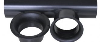
Coil inductance. The formula is at the link.
In practice, sections of such filters are cascaded to obtain different filters with the required bandwidth. But there is one drawback to filters that have an inductor. Coils are expensive, bulky, and have many parasitic parameters. They are sensitive to background noise, which is magnetically induced from nearby power transformers.
Of course, this drawback can be eliminated by placing the inductor in a mu-metal screen, but this will only make it more expensive. Designers try to avoid inductors whenever possible. But, thanks to progress, coils are currently not used in active filters built on op-amps.
I recommend watching a video on the topic “How an electric filter works”:
Practical work
We smoothly move from theory to practice. I got vintage speakers called Kompaktbox B 9251. And the first thing that was done was listening.
With a cold stone, the sound was on average not bad, and if we speak specifically, in some places it was good, but in others it was haphazard. They refused to play with a warm lamp at all. Based on these observations, it was concluded that there was deep buried potential. An autopsy showed that German engineers decided to make do with one single capacitor in series with the RF head. The frequency response measurement gave a terrible picture. In the figure, the frequency response of one speaker, a curve with a deep hole at 6 kHz due to poor connector contact, do not pay attention to it. The frequency response of HF and LF separately is given below.
↑ Printed circuit board
As an op amp, I used a quad op amp of type K1401UD2. This board is for him. For a stereo system of two two-way speakers, it is enough to assemble 1 board.
#09/02/2021
Signet From Igor (Datagor) for LM324, LM2902, LM224, LM124:
I combed the PCB, changed the power supply for imported op-amps (!), signed the components according to the diagram, signed the inputs and outputs, etc.
GND - general power supply, ground; +V, −V — power supply ±12V … 15V; IN1, IN2 - audio inputs (LC, PC) from the source (sound card, DAC, pre, phone); HF1, HF2 - HF band outputs for amplifiers; LF1, LF2 - low-frequency band outputs for amplifiers; Power supply capacitors, which are not on the diagram: C50, C53 - 100μF ... 470μF 16V (electrolyte); C51, C52 - 0.1μF ... 0.68μF (film or ceramics); Op-amps - LM324, LM2902, LM224, LM124, etc., quadruple (dip-14 quadruple opamp).
Note:
Imported op-amps and K1401UD2 have inverted power supply! A joke by domestic developers. Choose a PP according to your op-amp.
Pick up the PP in the files.
Crossover Frequency
Now is the time to think about the frequency of the section. Typically, the crossover frequency is selected in flat horizontal areas, away from resonances and blockages, trying to avoid sudden irregularities as potential sources of distortion... And if you remember that there is a phase about which little is known, and if it is known, then you can’t add up the vector frequency response on a piece of paper, but from - due to the curvature of the phases, even on a perfectly flat frequency response, something will come out, something will fail to a greater or lesser extent. You also need to remember what the speaker itself, especially the high frequency, can provide; for example, you shouldn’t force an inch dome to play from two, much less one, kilohertz, even if it is capable of playing them back according to the frequency response.
Don't forget that high excursion creates intermodulation distortion, so each speaker size has its own frequency range. In light of the above, the concept of crossover frequency is spread out over the area where it is worth mixing, and the end point is selected differently, for example by ear. Or not to select at all, but more on that later.
So, let's look at what unique speakers we got. The high-frequency driver begins to fall at 1.3 kHz, which means it cannot be allowed lower. On the other hand, the subwoofer tries to play at as low as 10 kHz, with varying degrees of success. However, common sense dictates that launching it above kilohertz is a bad idea. And what should you do if the operating ranges of the speakers do not intersect?
There are two options: if the declines have an adequate steepness, then it is best to drive into a hole, especially if the hole turns out to be wide. In our case, when the declines are as steep as cliffs, we must stay away from the steepest of them. Most often, this can happen with a high-frequency driver; it is always difficult for them to work at the lower limit of the range, so it is more expedient for them to make their life easier by entrusting the reproduction of the lower part of the range to a low-frequency speaker, which will play at least poorly, but will not spoil. Therefore, we limit the range to the area from 1.5 kHz to 2.2 kHz.
Making your own acoustics
- home
- Articles
- DIY acoustic system\ AKTON
|
|
The process of creating a do-it-yourself acoustic system (hereinafter referred to as speakers) can be divided into several main stages:
- Selecting the composition of speakers based on the requirements for speakers,
- Calculation of acoustic design,
- Design development and manufacturing of the speaker housing,
- Calculation and production of separation filter,
- Debugging.
When starting to design a speaker system, it is necessary to formulate the requirements for it:
- Purpose and operating conditions,
- Required sound pressure level,
- Reproducible frequency range,
- Execution option (with built-in amplifier or without amplifier),
- Dimensions and permissible weight.
You also need to decide on the type of construction:
- Type of acoustic design,
- Number of stripes
- Design features and design.
Based on this information, you can begin to select speakers and other system components, and calculate the acoustic design and filters.
The speaker selection criteria are discussed in detail here. A separate article is also devoted to the calculation of filters for speakers on our website. In this article we will consider the issues of calculation and production of acoustic design for speakers.
So, after selecting the speakers, the acoustic design is calculated, and then they begin to develop the housing design.
Calculation of acoustic design
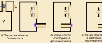
Let us recall that the emission of speakers in the low-frequency region is determined by the joint work of the woofer and acoustic design. There are several types of acoustic design: open, closed and phase inverted. The article focuses on phase-inverted systems, since, subject to correct calculation, they have maximum LF radiation efficiency, which is why they are widely used among systems intended for professional sound recording.
The calculation of the acoustic design of the phase-inverted type is carried out according to the method proposed by engineers Thiel and Small. According to this technique, the speaker is a high-pass filter.
The task of calculating the AO comes down to determining the required internal volume and frequency settings of the bass reflex, which are optimal for a given woofer. Calculation criteria can be different and depend, first of all, on the purpose of the speaker. Systems designed for sounding events, as a rule, should have maximum radiation efficiency in the LF region. At the same time, the subjective feeling of “lower end” should be maintained as power is added. The bass reflex tuning frequency for such speakers is usually chosen around 40-50 Hz. For example, such systems are successfully used for scoring dance floors, where the impact is more needed than the sub-bass.
Modern methods of calculating AC imply computer modeling in special programs. This approach allows you to optimize speakers not only in terms of the amplitude-frequency response of sound pressure, but also in terms of a number of other parameters. One such program is BassBox 6 Pro. This program allows you to make a comprehensive calculation of the characteristics of the speaker, which is a woofer in an acoustic design. The calculation method makes it possible to find a compromise between the various requirements for the AS using the method of successive approximations.
Let's look at the basic techniques for working in the BassBox program:
Enter the program by double-clicking on the corresponding shortcut on the desktop.
In the window for selecting a work option (Fig. 1), select Open Design Window .
Figure 2 shows the main program window.
The BassBox program allows you to work with several speakers at once and compare them with each other based on various characteristics. Data for each speaker is saved in a separate tab called Design . Designing a New Speaker begins by creating a new tab by clicking File -> New Design .
Clicking the Driver on the Design opens the speaker parameters window (Fig. 3). It contains all the information related to a specific speaker model.
Data can be entered manually, but it is better to download the required speaker model from the database.
The BassBox 6 Pro program contains an extensive database of speakers from world famous manufacturers. It is possible to supplement this base with other speakers. To do this, you first need to enter the name of the new manufacturer into the database. To do this, open the menu Edit -> Database -> Edit Company Data (Fig. 4). In the Name , enter the name of the company and check the box next to Manufacturer , if desired, fill in other fields containing information about the manufacturer, and then click Save .
After this, you should save the new speaker model in the database. To do this, enter data for the speaker into the Driver Properties (Fig. 5).
Description tab provides general information about the dynamics.
In the Paramerters , the small-scale parameters of the speaker are indicated (Fig. 6). In this case, it is not necessary to fill in all the parameter fields, but it is enough to indicate only some of them. In this case, the remaining parameters can be calculated using the built-in calculator ( Calc and Calculate All ).
All til-small parameters are interconnected in dynamics. The presence or absence of contradictions between parameter values is indicated by the color of the signal LED located to the left of the parameter field. The red color of the LED indicates a strong mutual inconsistency of the parameters, yellow - insignificant, green - no inconsistency.
You can also fill out the Dimension , which contains information about the geometric dimensions of the speaker (Fig. 7). This information will be automatically used by the program when it is necessary to calculate the free internal volume of the housing.
Once the tabs are complete, click Add this Driver to Database .
To extract the desired speaker from the database, click Load from Database in the Driver Properties (Fig. 3). The window shown in Fig. 8 will open. In the drop-down lists, select Company Name and Driver Found , then click Load .
After loading the basic parameters of the woofer, you need to indicate the number of speakers to be installed, the installation method, as well as the interconnection diagram if the number of speakers is more than one. Configuration tab is intended for this (Fig. 9).
To set the initial parameters of the acoustic design in the Design 1 , click Box . This will open the Box Properties .
Description tab is designed to save basic information about the speakers.
The speaker housing parameters are set in the Box Design (see Fig. 10) and Vents (see Fig. 11) tabs. The first indicates the type of acoustic design (Type = Vented Box - bass reflex), volume (Vb) or body dimensions (Dimensions) and bass reflex tuning frequency fb.
In the Vents tab, the design parameters of the FI ports are indicated.
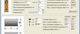
By setting the required parameters of the speaker and housing, you can make a trial plot of graphical characteristics. To do this, click Plot on the project's Design . The window shown in Fig. 12 will open. These characteristics can be further optimized by changing the acoustic design parameters (body and bass reflex dimensions).
Let's briefly consider the most important characteristics and criteria for their evaluation:
- NA - frequency response of sound pressure level at a distance of 1 m, when supplying a power of 1 W.
We must strive to achieve the greatest uniformity; - CA - frequency response of the sound pressure level at a distance of 1 m, when the rated power is supplied.
Shows the amount of sound pressure that the speaker can provide. - AP – Acoustic power.
We must strive to reduce the depth of the dip in the low-frequency region and not allow a dip of more than 3-4 dB; - CD – Displacement amplitude of the diffuser (voice coil).
It is necessary to strive not to allow the maximum amplitude of the voice coil displacement to exceed Xmax within the frequency range reproduced by the acoustic system; - VV – Air flow speed in the bass reflex pipes.
It is necessary to strive to reduce the air flow speed in the FI pipe, no more than 15 m/s.
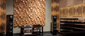
Speaker production
Let's look at some features of the manufacture of speaker cabinets:
In most cases, speaker cabinets are made of plywood with a thickness of 15 and 18 mm.
The housing structure must be durable and airtight. It should be taken into account that during operation of the speaker, increased pressure is created inside the housing. This circumstance leads to losses occurring in the unsealed housing, which manifest themselves in the fact that air begins to leak out of the cracks. This may manifest itself in the appearance of additional sounds when the speakers are operating. In order to avoid this, all joints must be carefully glued with wood glue. The panels are twisted with self-tapping screws every 7-10 cm. The heads of the screws are buried and subsequently puttied.
It is advisable to equip panels of significant sizes with stiffening ribs, because In insufficiently reinforced panels, an oscillatory process may occur, leading to a loss of clarity in the reproduction of low frequencies. It is undesirable to use a removable cover in the design, because This design solution, as a rule, also leads to a decrease in the tightness and rigidity of the housing.
All speakers with an open back side that are part of the speaker system, except for the LF speakers, must be isolated from the internal volume of the housing to prevent the influence of LF radiation on them. If you plan to equip the speaker with a built-in amplifier, then it is advisable to allocate a separate chamber in the speaker body for it. This is especially true for open printed circuit amplifiers. When designing speakers, it is necessary to ensure the possibility of ventilation of system components, and take measures to create more favorable operating conditions for them. Let us remind you that during prolonged operation at high power, heating of the magnetic circuit of the speaker can reach 70 degrees.
To summarize all of the above, let us remind you once again that to produce high-quality speakers, not only high-quality speakers are needed. It is important to correctly design and manufacture the speaker cabinet, make a rational choice of drivers (HF heads) and calculate the crossover filter. It should be remembered that the parameters of the phase-inverted speaker cabinet are calculated in relation to a specific model of the woofer. You can independently calculate the bass reflex based on the Thiel-small parameters of the speaker, using specialized programs and techniques. Based on the calculated data on the volume of the cabinet and the parameters of the bass reflex, design the speaker cabinet. For the speakers produced, ACTON engineers have designed speakers suitable for most audio applications. The housings of these speakers are optimized according to a number of parameters, such as maximum output at low frequencies, the best conditions for thermal convection of the speakers inside the housing, shape and size indicators, ease of transportation, etc. Documentation has been developed containing a set of drawings for the manufacture of speaker housings. All speakers have been tested under real operating conditions. According to the documentation, speaker enclosures are made of standard plywood. The outer surface of the body can be painted or covered with carpet. Technical documentation for speaker enclosures in PDF format is available on our website for free access and you can use it to make a speaker system with your own hands.
Filter order and quality factor
The next parameter that you need to decide on is the order of the filter and its quality factor. This article will consider two orders, first and second.
- With the first, everything is simple: there is a coil, there is a capacitor, we calculate their parameters for the required cutoff frequency and, if necessary, adjust the values until the desired frequency response, phase response, and frequency response are obtained.
- The second order is trickier, there are already two coils and two capacitors. A parameter such as the quality factor depends on the values of the nominal values; it determines the steepness of the frequency response decline and, to some extent, the phase shift. Since the influence of the phase shift and slope cannot be speculatively estimated, all that remains is to simply choose which way to think. And think here in the direction of low quality factor, read more inductance in the coils, less capacitance in the capacitors.
How to choose an order. Here we are guided by already familiar considerations about what emitters, especially high-frequency speakers, are capable of. If a big move is contraindicated for him (as in our case), then we give preference to the second order.
To complete the picture, it should be mentioned that the order also determines the degree to which the speakers work together, but this is information for independent reflection.
Crossover calculation
Homemade crossovers for car acoustics
To connect a 2-way (see Two-way acoustic system and its advantages) or other acoustics with a large number of bands to 1 channel of an amplifier or PG, you need some kind of separate device that separates the signal. At the same time, it must allocate its own frequencies for each band. These devices are called filters or crossovers.
Note. As a rule, component speakers already come with a passive crossover. It was prepared by the manufacturer and was designed from the very beginning.
But what if you need to divide the frequencies according to a different scheme (for example, if a set of acoustics is assembled from separate components)? In this case, we are talking about calculating the crossover. Let us note right away that calculating the crossover is not at all difficult and you can even make it yourself.
Crossovers for acoustics for Pioneer cars professional
Below are instructions on how to calculate the crossover:
- Download a special program. This could be Crossover Elements Calculator on your computer;
A special program for calculating crossover Crossover Elements Calculator
- We enter the resistance of the low-frequency and high-frequency speakers. Impedance is the nominal value of the acoustic impedance, expressed in Ohms. Typically, the average value is 4 ohms;
- Enter the crossover frequency. Here it will be useful to know that the frequency must be entered in Hz, but in no case in kHz.
Note. If the crossover is of the second order, then you must also enter the type of crossover.
- You can get the expected result by clicking on the calculation button.
In addition, you need to know the following:
- The capacitance of capacitors, or rather their value, is entered in Farads;
- Inductance is calculated in Henry (mH).
The filter calculation scheme looks something like this:
How to calculate a filter
Speaker impedance characteristic
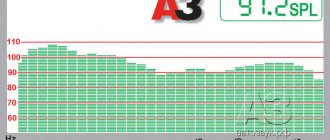
When everything is more or less clear with the approximate parameters, it’s time to move on to practice. We take the impedance characteristics of the speakers. In order to estimate the resistance, the graph has a ladder in steps of one ohm. A jump at 110 hertz is a switch from 10 ohms to 20.
Of course, with such humps, not a single filter will work normally, and especially not a low-pass filter. In general, this rise does not interfere with the work of the high-pass filter, however, as mentioned earlier, such a rise at the end of the range will lead to a rise in high frequencies if the amplifier has a high resistance. This can also be used for good, leaving the rise small.
To level these rises, the so-called Zobel chain is used. It consists of a resistor and a capacitor connected in series. The easiest way to select it is by scientific poking: take a rheostat, a handful of capacitors, and move it all until you get a straight line.
For an approximate idea of what depends on what, I provide a set of graphs for various capacitances and resistances. The step starts at 10 ohms.
Knowing the minimum resistance of the low-frequency link, you need to bring the high-frequency link to the same. There are many options for how to connect two resistors and a Zobel chain, and anyone who has decided to take such a brave step as mixing is able to determine the type of connection and resistor values, so it is unnecessary to describe this procedure here. Specifically, in these speakers, based on the results of preliminary listening, it was decided to leave the original 2.2 ohm resistors and the Zobel circuit parallel to the tweeter.
Quasi-universal filter for 3-way speakers such as S-90, 50AC-106, 35AC-016, 35AC-021 and others
An article for those who listen to music of quality not lower than CD, but better in increasing quality:
- CD;
- SACD;
- rip vinyl record 24/96, even better 24/192, or 32/192;
- rip a vinyl record using a Korg MR-1000.
In the beginning there was vega... 50 AS-106 (almost according to the Bible). The sound was good, but still, the noise of the wind, the rumble of thunder, the rustling of the stream, and the voices of the singers were not similar to those reproduced by the Sennheiser HD-215II headphones. I bought a Corvette 150 AS-001. I restored the speakers (did nothing else). And the voice of the singers became natural, and no matter what you listened to, all the music began to be reproduced correctly (as in life). What's the difference???
Both speakers have 3 speakers. Moreover, the high frequencies are almost identical, the midranges are also the same, only the low frequencies of the corvettes are larger. Well, then they should play equally naturally, only the Corvettes should play louder due to their large bass frequencies. But this is not the case. Vega sound due to sizing, sealing, etc. (was carried out earlier) did not improve much. And then my gaze fell on the diagrams of their filters.
Corvette 150 AS-001:
It's called find three differences. It became clear that the filter needed to be changed. The engineering approach suggested that, based on the existing structure of a known working filter, it was necessary to modify the existing one so that:
- 1. the alteration was minimal;
- use the maximum available filter elements;
- there was an opportunity to return everything to its original state.
Unfortunately, at that time I did not have a tool for measuring inductance, and even with this condition I managed to bring the sound closer to the original.
Then I bought 35 AS-016 “Orbita” and also modified the filter. But it was possible to change the filter completely correctly on 35 AS-021 “Estonia”.
That's where the sound was poor! And everyone praises them. Yes, there are speakers, and housings, Yes, the sound is just a nightingale. Yes, Vega plays much better with native filters.
The purchased “Estonia” did not have filters - another (I don’t know what to call it) padawan, having heard enough of Yoda, removed all the filters and left instead 1 µF on the high-frequency speaker and 10 µF on the midrange (so that the tube amplifier would whisper at least something).
Thanks to this site for the RLC meter program. I wound the coils as in the circuit, assembled the filter according to the original circuit and, as I already said, in the absence of a filter they played no worse! Then my eyes turned to circuit 35 AC-016 (the original circuit lacks only one coil in the midrange filter, C2 = 2 µF, remove R2, add a resistance of 10 Ohm/10 W to the low-pass filter - according to the wiring diagram for this speaker. 5 Ohm/2 W in front of the tweeter (so it doesn't burn out), and the circuit is much simpler than the Corvette. The coils were re-wired, capacitors were added, but the sound should still have been better.
Having looked carefully at the characteristics of the speakers, it became clear that the HF speaker 35 AC-021 cannot reproduce frequencies below 5000 Hz, and the filter of the 35 AC-016 MF/HF is 4600 Hz. It became clear that the crossover frequency should remain 6000 Hz. Another problem was the humming of the woofer instead of hitting the drum - I managed to get rid of it by removing (shorting) resistor R3.
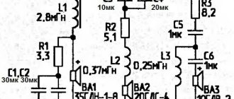
The resulting diagram. Quasi-universal filter for 35 AC-021:
A little about additional filter elements:
- L5+C13 is the low-pass component in the mid-pass filter;
- R3 attenuates the cutoff of the high-frequency component of the music in the mid-range filter;
- L2 additionally cuts low frequencies penetrating after the filter (C2+C3+C11)+L4+C12 (selected experimentally) - makes the voice clean and transparent, preventing the midrange speaker from resonating. Removes the feeling of “insufficient high frequencies”, which is why they add HF with an equalizer and burn the HF speaker.
C8+C1+C7 shifts lower than the cutoff frequency of the low-pass filter (sorry, the woofer does not normally reproduce frequencies above about 800 Hz.
Now where to get the wire and frame for the coils. I took the frame by disassembling the video cassette and removing the film from it in 5 minutes. I took the wire from the 36 V starter coil (if you know an electrician at a large enterprise, then it’s not a problem - you need 2 pieces). The diameter of the wire is approximately 0.45-0.55 mm, since small currents flow through the midrange, this wire is quite sufficient. You can also disassemble another suitable coil, 120 turns per video cassette reel frame - 0.32 mH. To obtain 0.77 mH - about 190 turns.
I did this - I tried to wind it more “in cultural bulk” at once - turn to turn is not necessary, and then reset the turns to the desired inductance, without disconnecting the probes, controlling the process with the RLC filter program. Or (if it turned out to be less) I isolated the stripped area with a piece of electrical tape and added the expected number of turns, and then reeled it back to normal.
A little about the joke about the RLC filter program. It is not necessary to select 100 Ohms very precisely (place near the crocodiles). All the same, the sound card will be rather weak. And yet, it is better to make the cord going to the microphone input shielded, and from the output of the sound card you can take it from the headphones. The total length of the hook should be 1-1.5 m (to reach the coils in the column). Before winding your coils, the program readings need to be calibrated - measure the existing coil in the column (unsoldering one end from it) and calculate the correction factor.
Example: L3 = 0.17 mH, but shows 0.19 mH. This means 0.19/0.17=1.12. You also check on coil L2 and select the average coefficient. This means that when you wind 0.56 mH it should show 0.627 mH, and 1.3 mH should show 1.456 mH.
When checking the speakers, screw the back wall with at least 4 screws! If all the speakers are working (and not the high frequencies stuck on the core, and the midrange not clinging to the core, enriching the sound with side sounds), the circuit works immediately.
Calculation presupposes, but God disposes…….
- I shifted the crossover frequency of the mid/low-pass filters and moved them closer to each other - as a result, the singer’s voice, intense mid-range frequencies (between midrange and low-pass) and the clicks of the record became correctly audible. (These are indicator indicators).
- Shifted the crossover frequencies of the high-pass and mid-range filters towards each other. The result is that the voice has become more natural.
When developing the filters, the plant engineers were not fools, but the economists saved 2% of the cost of the columns on the filter and we have what we have...
The filter option is final, no further changes will be made to the scheme:
Flattening filters
Now the final stage begins - mixing the filters. It's time to wind the reels... or not to wind them? You are always too lazy to wind, there are no wires, frames, or specific inductance values. In view of these reasons, after searching in the trash, we found pairs of 0.8 mcg and 3 mcg coils - we had to build on them. In extreme cases, you can always rewind or unwind the excess.
The graph shows that the section fell into the region of 1.8 kHz, which fits well within the intended boundaries. By selecting capacitors we managed to achieve the following impedance. There are two bumps at the crossover frequency, but their height is less than half an ohm - this is not critical. This is not its final form; subsequently the resistor in the Zobel circuit of the tweeter was slightly increased.
The above pictures show the frequency response of both the filter itself and the frequency response of the speakers with it turned on.
What is an electric filter
An electrical filter is a device for selecting desirable components of the spectrum (frequencies) of an electrical signal and/or suppressing unwanted ones.
For other frequencies that are not included in the passband, the filter creates large attenuation, up to their complete disappearance. The characteristics of an ideal filter should cut out a strictly defined frequency band and “squeeze” other frequencies until they are completely attenuated. Below is an example of an ideal filter that passes frequencies up to a certain cutoff frequency value.
In practice, such a filter is impossible to implement. When designing filters, they try to get as close as possible to the ideal characteristic. The closer the frequency response characteristic is to an ideal filter, the better it will perform its signal filtering function.
Filters that are assembled only on passive radio elements, such as an inductor, capacitor, resistor, are called passive filters . Filters that contain one or more active radio elements, such as a transistor or, are called active filters .
In our article we will look at passive filters and start with the simplest filters, consisting of a single radio element.
Speaker phasing
This brings the mixing to an end. All that remains is to decide on the phasing of the speakers. There are at least three ways: by ear, by the shape of the frequency response and by the phase shift at the crossover frequency. If the speakers have a moderately linear frequency response and phase response, and the filter does not greatly increase the phase at the crossover, then when the correct phase changes to an incorrect one, a deep dip will appear at the crossover frequency, it is difficult to miss it. In this case, it is worth adjusting the phase according to its shift. This can be done with an oscilloscope by feeding the horizontal deflection signal from the amplifier, and the vertical deflection signal from the microphone.
A sine wave with the crossover frequency is supplied to the amplifier input and, without changing the relative position of the microphone and speakers, the high-frequency and low-frequency speakers are switched. Based on the similarity of the Lissajous figures, a conclusion is drawn about the equality of the phases of the emitters. This method works well for first order filters. With the curvature of our speakers, this method does not justify itself, so we compare the frequency response at different phasing.
The second option is noticeably worse. However, the first one is not the ultimate dream, but since moving the inductance of the coils is not easy, and it’s too lazy to tinker further, everything was left as is.
Filter assembly
In conclusion, a few words about the assembly. The filter uses relatively large capacitances, 20 µF, 27 µF, and there is not much space in the case; there is not enough paper or film. You have to put in electrolytes. And if in a low-pass filter the sound does not suffer much from their use, and in the main circuit they may not be heard at all, then in a high-pass filter it is dangerous to neglect the sound of capacitors. It is for this reason that paper MBGO and film K73-16 were used, and all electrolytes were shunted with paper MBGO at 4 μF.
You should not get carried away with paralleling very different capacitors. The main criterion here is the loss tangent. If, for example, you put audiophile polypropylene in a shunt to a paper capacitor, then most likely the tops will come out and they will be acidic. Probably, here we can draw an analogy with internal resistance, comparing the loss tangent with it: the smaller it is, the more signal will pass through the capacitor, and since the capacitance of such a high-quality capacitor is smaller, only the high-frequency part of the signal will pass through it, hence we have increased levels top But this is only an analogy for a better understanding of the effect of shunts on sound.
There are plenty of articles written about how to distribute the coils and what thickness of wires to use; I will not repeat them here. It’s easier to show a picture (here the high-frequency driver socket is soldered incorrectly, it should be after the resistor).
Single element filters
As you understand from the name, single-element filters consist of one radio element. This can be either a capacitor or an inductor. The coil and capacitor themselves are not filters - they are essentially just radio elements. But together with the output resistance of the generator and the load resistance, they can already be considered as filters. Everything is simple here. The reactance of the capacitor and coil depends on frequency. You can read more about reactance in this article.
Single-element filters are mainly used in audio technology. In this case, either a coil or a capacitor is used for filtering, depending on which frequencies need to be isolated. For a high-frequency speaker (tweeter), we connect a capacitor in series with the speaker, which will pass the high-frequency signal through it almost without loss, and will dampen low frequencies.
For the subwoofer speaker, we need to highlight low frequencies (LF), so we connect an inductor in series with the subwoofer.
The ratings of single radioelements can, of course, be calculated, but they are mainly selected by ear.
For those who don’t want to bother, hardworking Chinese create ready-made filters for tweeters and subwoofers. Here is one example:
On the board we see 3 terminal blocks: input terminal block (INPUT), output terminal block for bass (BASS) and terminal block for tweeter (TREBLE).