Articles
Crossover calculation for acoustics75
Calculating the crossover for acoustics, as you know, is a very important operation. There are no ideal acoustic systems in the world that can reproduce the entire frequency range. And then certain parts of the speaker spectrum come to the rescue. For example, if you need to reproduce low frequencies, use a subwoofer, and to reproduce high frequencies, install midbass. When all these speakers together start playing, confusion can occur before reaching one or another emitter. For this reason, an active or passive crossover for acoustics is necessary. In this article we will learn why filter calculations are needed, consider passive crossovers, and learn how they are built using inductors and capacitors.
Crossover calculation
Homemade crossovers for car acoustics
To connect a 2-way (see Two-way acoustic system and its advantages) or other acoustics with a large number of bands to 1 channel of an amplifier or PG, you need some kind of separate device that separates the signal. At the same time, it must allocate its own frequencies for each band. These devices are called filters or crossovers.
Note. As a rule, component speakers already come with a passive crossover. It was prepared by the manufacturer and was designed from the very beginning.
But what if you need to divide the frequencies according to a different scheme (for example, if a set of acoustics is assembled from separate components)? In this case, we are talking about calculating the crossover. Let us note right away that calculating the crossover is not at all difficult and you can even make it yourself.
Crossovers for acoustics for Pioneer cars professional
Below are instructions on how to calculate the crossover:
- Download a special program. This could be Crossover Elements Calculator on your computer;
A special program for calculating crossover Crossover Elements Calculator
- We enter the resistance of the low-frequency and high-frequency speakers. Impedance is the nominal value of the acoustic impedance, expressed in Ohms. Typically, the average value is 4 ohms;
- Enter the crossover frequency. Here it will be useful to know that the frequency must be entered in Hz, but in no case in kHz.
Note. If the crossover is of the second order, then you must also enter the type of crossover.
- You can get the expected result by clicking on the calculation button.
In addition, you need to know the following:
- The capacitance of capacitors, or rather their value, is entered in Farads;
- Inductance is calculated in Henry (mH).
The filter calculation scheme looks something like this:
How to calculate a filter
DIGITAL FILTER: TYPES AND DIFFERENCES
You've probably come across a variety of digital filters in your players. If previously the choice was literally between fast roll-off and slow roll-off, today it has become much wider. For example, my player gives me an alternative in the form of seven different filters. Another question is that they do not have a decisive influence on the sound. However, there is still one option that, for some inexplicable reason, I like more than the rest. When you come across equipment during reviews, you also find the best option for yourself and settle on it. The main thing to remember is that there are no right or wrong digital filters. They are all doing their job. Differently.
When talking about digital filtering, the concepts of phase, attenuation and ringing are often used. Let's start with the last one. Ringing is an artifactual sound vibration that can either precede or follow an input pulse signal. Its behavior is determined by the operation of the digital filter.
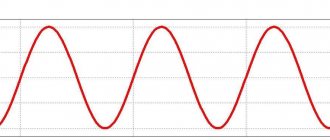
A discrete pulse signal has a maximum amplitude and a minimum duration. Roughly speaking, one sample with maximum amplitude. But the influence of the chain of transformations and processing leads to the fact that the reconstructed signal is not reproduced perfectly. If you turn to the text about DACs, to the section about why delta-sigma DACs were previously criticized. And there you can find three pictures depicting a meander and an example of how filtering affects the formation of a preliminary “ringing” when playing a test signal.
The figure above shows the test signal in the frequency section and in the time section. An applied discrete signal in the time domain will not be discrete. In this case, the filter “provides” it with two phases of damped or rising oscillations. That is, that same ringing, after-sound. Why is this happening? To answer this question, we need to explain how a digital filter works from a computational perspective.
LINEAR PHASE FILTER
A digital filter “splits” the audio signal into several samples. Several - not three or four, but a large enough number so that you can manipulate the order in which the filter gain is applied. Next, a certain gain is applied to each sample. In this case, the highest gain was applied to the middle sample (median), then each subsequent sample from the median (zero sample) received its gain lower than the median. At the output, the filter sums the resulting products. This is the final analog signal after oversampling and filtering.
But the imperfection of the equipment and the limited frequency range leads to the possible audibility of pre- and post-echoes - that same ringing. Consequently, the perception of sound, its character, and sensation in space also depend on the order in which the filter gain is applied.
The previous figure showed the principle of working with a linear phase filter signal. With this filtering, the ringing preceding and following the main signal receives mirrored gain. As a result, we have not only an after-sound, a ringing decay, but also a preceding pre-echo. That is, even before the signal occurs, there is a parasitic signal.
FILTER WITH MINIMUM PHASE
In order to solve this problem, a minimum phase filter was applied. It works on the same principle of distributing gains and summing up the gain results of each sample sample. But the zero sample, which receives maximum gain, is shifted from the median (middle) of the sample to its beginning. The result is that there is no pre-echo, but the post-echo, the ringing, gets more amplification. Since in the linear phase filter discussed earlier, the lower-order gain was divided equally between those preceding the zero sample (minus-first, minus-second...) and those following it (first, second...). then the influence of each of them was balanced. In the case of the minimum phase, we see the absence of preliminary ringing. In turn, the aftersound is more pronounced.
In addition to pure linear and minimum phase filters, modified apodizing filters are also used. Apodization is a filtering method used particularly for audio signal processing. It is used to reduce the influence of pre- and post-echo in both linear-phase and minimum-phase filters.
PULSE TRANSIENTS
Having dealt with the main types of digital filters, let's move on to special cases. Now we will talk about working with impulse transient processes (or impulse responses), namely, how those very fast/slow/super slow roll-offs affect the sound of the system.
If a linear or minimal phase filter works differently with the signal and ringing phases, then special cases of filters determine how they work with transient processes. So, if super slow roll-off ensures an almost complete absence of transient processes (ringing), then fast roll-off does not suppress transient processes. They can either precede or follow the signal, which is characteristically reflected in the sound.
An illustration of the difference in the operation of fast roll-off and slow roll-off filters is shown in the figure above. In addition to the fact that the filters differ in their frequency response curve (the HF roll-off on slow starts earlier than on fast), there are also differences in their impulse response. With a slow decay, the impulse response is minimal, but with a fast decay filter and a flatter frequency response in the HF region, we get a more pronounced and rich impulse response. Depending on the phase filter type, this can be post-ringing or pre- and post-ringing. Do not forget that there is simply no single correct filter. Thus, the filter must be selected both for a particular music and equipment, and based on personal preferences. And don't forget about the premises!
Filters of different order
To clearly understand the crossover calculation scheme (see Homemade crossovers for acoustics and their purpose), you need to understand the difference between filters of different orders. This will be discussed below.
Note. There are several orders of crossover. In this case, order means the crossover parameter, which characterizes its ability to attenuate unnecessary frequency signals.
First order
The circuit of a 2-way crossover of this order looks like this:
2-way 1st order crossover
The diagram shows that the low-pass filter or low-pass filter is built on an inductor, and the high-pass filter is built on a capacitor.
Note. This choice of components is not accidental, since the resistance of the inductor increases in direct proportion to the increase in frequency. But as for the capacitor, it is inversely proportional. It turns out that such a coil perfectly transmits low frequencies, and the capacitor is responsible for transmitting high frequencies. Everything is simple and original.
Frequency filter according to the 1st order circuit
You should also know that first-order crossovers, or rather their rating, depend on the selected crossover frequency and the value of the speaker impedance. When designing a low-pass filter, you must first pay attention to the cutoff frequency of the low-pass and mid-range speakers (see How to choose speakers for a car radio on your own). But when designing a high-pass filter, you need to do the same with the high-pass filter.
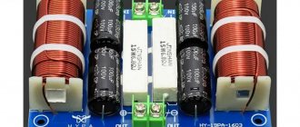
Filters for speaker systems without capacitors
Capacitors are an inevitable “evil” that audiophiles are forced to endure, gritting their teeth. Many types of capacitors “sound bad.” For example, the notorious H90 ceramics - due to the piezoelectric effect. What about other types, say, film? You could write a whole poem here. But is it possible to build frequency-dependent circuits without them, only using chokes (inductors)? It turns out that it is possible. And not only is it possible, but it is necessary!
My old acoustic speakers built before 1980 were occasionally modified. Due to a torn diffuser, the 4GD8-E head was replaced with a 5GDSh5-4 (this is almost the same thing), and at the same time the second one. The 25GD-26 heads were turned on “doublet” (“face to face”) (1). And the frame with the protective radio fabric had to be finally removed. But the filters remained the same.
At low frequencies - second order, at medium and high frequencies - third. And the frequency response in terms of sound pressure was not bad. But the sound...! There was no difference between different amplifiers, much less between copper and silver wires.
It's time to replace the filters. Which ones to choose? Over the years, a lot of conflicting information has appeared. Audiophiles especially criticized capacitors. At first it was advised to make filters no higher than the first order, then they refused to make such filters and built the fourth, and some even reached the sixth order.
We analyzed the group delay time (GDT) and phase response, and moved the RF emitter forward, backward... and even to the side. Complete “confusion”: from single-way speakers on 4A28 to 4-5-6-way... etc. Somehow, while sorting out printouts of materials from the Internet, I came across an article by A. Yurenin about sequential crossovers.
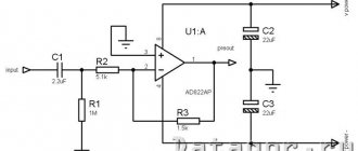
There the author says that they appeared in 1969. But I came across the schemes themselves back in 1961 (2). where the author refers to a German magazine on communications technology from 1959. The essence of the matter is not this, but this. that Yurenin presented a crossover circuit for acoustics that does not contain capacitors (the circuit is patented and is used in acoustic systems produced by Acoustic Reality).
Here is the diagram (Fig. 1). It's very simple. Since my speakers are also three-way, I decided to start converting the filters with this circuit. Let's do a little analysis. Let's draw the simplest sequential crossover, “first order”, as it is usually depicted (Fig. 2). There is a capacitor C1 here. but in Fig. 1 there is no such capacitor. But the L1-R1 link is added there. which is a low-pass filter for mid- and low-frequency emitters.
At L1, high frequencies are selected and fall into the RF emitter BA1. L2-RVAZ is another low-pass filter, which are allocated to the VAZ, and the mid-frequencies allocated to L2 fall into the midrange emitter BA2. That's all the wisdom! The main thing is that the resistance of the emitters is purely active.
But emitters (heads) of the electrodynamic type cannot have purely active resistance, since they have a coil with an iron core. Repeating the circuit according to Fig. 1 leads to a sad result: there are clearly few mid frequencies due to the inductance of the VAZ head. Let's take a look at the low-frequency emitter.
To carry out this work, you will need an audio frequency generator with Uout.max = 10V, an electronic voltmeter (for example, B3-38) or a multimeter. It is known that to equalize the input impedance of the speaker at a range of frequencies, the use of a Zobel circuit and a series circuit at the resonance frequency is required [3].
But a resonant circuit is almost never installed on the LF due to its bulkiness and the remoteness of the speaker resonance from the frequencies of the LF-MF/HF section (0.3...3 kHz). To select R1 and C1 (Fig. 3), you need to know the DC resistance of the VA speaker Re: and the inductance of its coil Lk.
The following formulas are recommended:
The Re of my two speakers connected in series is 7.2 ohms. Thus, R1 = 9 Ohm, and C1 =?. because Lk is unknown. To determine Lk, you need to measure the speaker impedance at different frequencies.
The measurement scheme is simple and is shown in Fig. 4. The results are summarized in Table 1. Dividing the readings of the voltmeter PV1 in millivolts by 10 (second line of the table), we obtain the resistance Zva in ohms (third line).
From Table 1 we find Fz—the frequency at which the inductive and active resistance of the speaker are approximately equal, i.e. frequency, where
Some authors suggest taking R1=Re. I took R1 = 8 Ohm, then C1 = 30 µF. You can use a paper capacitor of the MBGO type 30.0 × 160 V. The bottom line of Table 1 shows the results of measuring the resistance of a woofer with an RC Zobel circuit (8.2 Ohm, 30 μF). However, the compensation turned out to be quite good! Now the LF emitter can be included in the circuit according to Fig. 1. There will be no dip at mid frequencies.
The 5GDSh5-4 midrange driver has Re = 3.5 Ohm and the output is almost 3 times greater than the low-frequency head, and equalization of the output is required here. Having made measurements to determine Lk for this head, we will find the frequency Fz. from which Z begins to increase.
This is approximately 4...5 kHz. To equalize the output, it is advisable to include a series resistor, as shown in Fig. 5. without using a Zobel chain. A divider is formed with a transmission coefficient for the low-frequency gearbox:
The frequency Fz of such a circuit will increase 4 times and amount to 16...20 kHz, so the Zobel circuit will not be needed. And we will bring the input resistance to an acceptable value by turning on a parallel resistor R1 with a resistance of 15 Ohms, as shown in Fig. 6.
In this case, the equivalent resistance Z will be:
This allows you to include a midrange emitter in the circuit in Fig. 1. Including a series resistor with a resistance almost 4 times greater than Re reduces the nonlinear distortion of the midrange head, bringing the equivalent resistance of the generator closer to the current source.
By varying R1 and R2 (Fig. 6), you can accurately select the division coefficient required for the same output of the mid- and low-frequency heads. It is very important to note that at medium frequencies there are really no capacitors (except for C1 in the low-frequency link, Fig. 3), and the frequency of the low-mid frequency section can be shifted by changing only one inductance - L2 in Fig. 1.
HF emitter - 6GD11. Its Re=5.6 ohm. Zwa = 7.3 ohms at a frequency of 5 kHz and then increases to 12.5 ohms at a frequency of 20 kHz. Most often, the Zobel goal is not set, because the crossover frequency is 4...8 kHz, and the increase in Zwa with increasing frequency has a slight effect on the sound.
The choice of frequencies for the LF-MF and MF-HF sections is made based on the following considerations. Since first-order filters are used, the crossover frequencies must be at least 2 octaves away from the resonance of the corresponding emitter [3], i.e. ff-mid > 600 Hz (frez ~ 150 Hz for 5GDSh5-4), and ff-HF > 6 kHz (frez = 1.5 kHz for 6GD11).
To better protect the HF emitter from LF oscillations, it was necessary to place an additional capacitor with a capacity of 2.2 μF (K73-16, Umax = 160 V) in series with the 6GD11 emitter. Without it, some overtones appeared at higher volumes.
In the midrange driver I used an open design (a box without a back wall with dimensions of 220x140x75 mm). Now it can be easily deployed at the desired angle to the listener. I sealed the windows of the diffuser holder (basket) with cotton batting and thus brought the total quality factor to 0.65. The final circuit of the loudspeaker is shown in Fig. 7a.
Structurally, coil L2 is frameless and has a direct current resistance of RL2=0.4 ohms. If desired, the inductance of the coil can be easily changed (increased) by pushing into it a ferrite core (a piece of a magnetic antenna from the Ocean radio receiver) with a diameter of 10 mm and a length of 100 mm. In this case, the fLF-MF frequency changes by 2.4 times. Coil L1 on a winder on an open core ШЛ40х10 (one bracket), RL1=0.4 Ohm.
The input impedance Z of a loudspeaker with such a filter at different frequencies is presented in Table 2. The table shows that Z3 changes significantly: at a frequency of 2.5 kHz - 5.6 Ohms, and at 20 kHz - 11 Ohms. To equalize Z at these frequencies, you need to connect an RC integer to the filter input (Fig. 76).
Then Z3 changes at these frequencies as shown in the last row of Table 2. The total change in Z in the entire band from 80 Hz to 20 kHz does not go beyond 4.4...6 Ohms and only at a frequency of 3150 Hz is 6.3 Ohms. This flat Z-characteristic makes it possible to compare amplifiers with different output impedances (tube and transistor).
After listening to the speakers, I noted with satisfaction the excellent sound of my tube “single-ended”, noticeably better than the sound of a transistor UMZCH, which, however, was also not bad. Frequency response using a measuring microphone. Of course, I checked how possible this was in the living room.
But I did not measure the phase response and group delay. I just listened to the “sound” and decided that these filters would last me another 10 years. Or maybe branded speakers will sharply fall in price, then I’ll buy myself something that sounds better, without capacitors.
The influence of the Weiduka AC8.8 surge protector on the system sound
There, in the comments to the previous article, comrade @Crazzy, who had the chance to experience the influence of this particular “veyduka” on the sound of his system, did not speak very flatteringly about it: “It immediately blurs the texture, tightens up the dynamics, “pumps out air”, individual instruments are isolated in vacuum. Interestingly, the effect depends on the row of rosettes: on the left it is more pronounced, on the right - less, i.e. on the right is the lesser evil :).”
Well, let's check out what the Veyduca can do when it only has standard power cables connected to an amplifier, DAC and subwoofer.
There is an effect. It was possible to clearly formulate thoughts on the influence of the surge protector on the sound after two or three switches of the power plugs from a regular outlet to the “Veyduku” and back. I can say that my opinion differs from the observations of comrade Crazzy.
Firstly, it was not possible to identify differences in the sound of the left and right rows of sockets. Secondly, I would classify the overall effect of the filter as “positive”. The first thing that is clearly audible is the effect of the filter on the low-frequency range: the bass “collects”, becomes more elastic and sharp. This observation was recorded immediately after the inclusion of “veyduki” in the system.
To fix the remaining changes, it was necessary to change the track - the vocals and stage perfectly showed that the “filtering” did not pass by these ranges. With the addition of a surge protector, vocals become clearer and more intelligible. The construction of the stage is more clearly outlined in depth, since in general the mids and highs sound clearer and more detailed.
Well, these observations give a good idea of how differently changing a power component can be perceived on different systems.
Network cable and amplifier
We simulate a situation where a novice lover of high-quality sound, having read about the influence of network cables on the sound of the system, begins to think: why not try it? And he buys one single network cable. Of course, there can be many variables in such an experiment. But, one way or another, with certain components, such an experience may well take place (and for many it has already happened, judging by the reviews to the previous article).
At the moment I will act as an experimenter, since I did not have such experience.
So, the “stock” system includes the only non-stock component related to power supply - the network cable for the amplifier, connected to a regular outlet.
This is a difficult task. Again, as with the USB cable (which we'll get to later, by the way), it took about 5-6 cable switches (switching took a maximum of 10 seconds) to confirm or deny one or another aspect of the sound.
At first, it seems that a Furukawa copper cable “sounds” more advantageous, more perky or something. Upon closer listening, it became clear where the “enthusiasm” lies: Furukawa, in some way that only electrons can know for sure, produces a more dynamic sound at the output. Bass and high frequencies become a little more accentuated and better developed.
That is, in direct comparison, you can hear that when connected with a standard cable, we have a sort of analogy of “even” sound. A custom cable gives the impression that the edges of the frequency response are slightly upturned - what a blast! This technique is often used by audio equipment manufacturers to make the sound more impressive. But for the cable...
It is worth considering that these changes are not as significant as it might seem from my description. I think that in order to detect this difference, the listener may need some skill (we are training our ears, gentlemen!) and a lack of experience in the radio instrumentation industry.
High Pass Filter Calculation
So how can we do the calculation? To complete all the steps at home, you need to make one of the simplest automatic calculation tables in Microsoft Excel, but for this you need to be able to use the formulas in this program.
You can use this formula:
Where f is the cutoff frequency; R is the resistance of the resistor, Ohm; C is the capacitance of the capacitor, F (farads).
NON-OVERSAMPLING (NOS) DAC
I recently reviewed a wonderful new product - the iBasso DX300 player. There I accidentally discovered the NOS mode among the standard set of DAC filters. That is, the operating mode without oversampling. While the manufacturer took care to inform the public about the matrix structure of the DAC in the DX300, it did not about the presence of the NOS mode. And rightly so. After all, an interesting and useful feature of the player could simply be ignored by not particularly curious audiophiles.
So, we talked a little about what a NOS DAC is in this review. Perhaps it was precisely when this section was being written that the idea came to a series of articles “about complex things in simple words.” So, I repeat: NOS DAC is a DAC that works without oversampling (oversampling). And sometimes without a digital and/or analog filter. There are others like that. Of course, implementing a DAC without a filter at all requires a number of manipulations so as not to clog up the playback with noise. For example, pre- or streaming upsampling.
The key task that developers set when creating a NOS DAC is to get rid of the pulse transient characteristics that follow the filtering process. Removing the ringing is good. But then the DAC has only an analog filter at its disposal, which has some disadvantages, which we have already discussed. Moreover, an analog filter made on discrete elements can introduce its own phase and nonlinear distortions.
FIGURE NOS SIGNAL
As you remember, an analog filter interpolates an analog signal along the reference points of a step curve. Without an analog filter this will not be possible. We will encounter our fantastic creatures - aliases - who will walk around without control or supervision. Is this really that scary for us as listeners? On the one hand, no. Aliases will be beyond the threshold of the audible range. If half the sampling frequency is above 20 kHz, then the alias spectrum will lie beyond the ½ sampling frequency mark and “mirror” the spectrum of the useful signal, representing ultrasound. On the other hand, alizes “eat up” part of the useful dynamic range. Thus, by refusing analog filtering, we get rid of filter distortion, but we get intermodulation distortion and lose part of the dynamic range.
UPSEMLING AND NOS DAC
In some cases, you can get a clean signal without filtering. In what? If the initial recording (namely the original file) was made at a sampling frequency above 44.1 kHz. Today, the generally accepted format for digital studio recording is 24 bit 88 kHz, less often 96 kHz. For some reason, it is believed that 88 kHz is easier to work with. Not the point. That is, such a recording can be played on a NOS DAC without a twinge of conscience and without fear of getting significant distortion.
Let's say we have a standard CD rip. That is, the usual 16/44.1 format. In this case, there is a way out in the form of upsampling audio files. In addition to preliminary upsampling, on-the-fly processing is possible. Fortunately, computing power today allows this even in a portable device. This is not about improving the source file! This cannot be done by simply pressing a button. But adding zeros to the high-order bits allows you to increase the sampling rate of the reproduced audio signal. Consequently, in the absence of a filter, this will allow aliases to be suppressed. If from 44.1 kHz we increase the file sampling frequency to 44.1 * 16 = 705.6 kHz, then ½ of the sampling frequency will be at 352.8 kHz! Aliza, goodbye.
NOS DAC is not a death sentence or a panacea. This is just another option, a different approach. Which allows you to implement the DAC circuit a little differently. On the one hand, such a circuit will be simpler and less demanding on analog filtering. But this will also require upsampling of files for high-quality implementation. However, avoiding oversampling and digital filtering can give the most natural sound. iBasso succeeded - the NOS mode seemed the most pleasant to my ears. That's where I stand.
Terms and components
The experimental conditions have not changed; the composition of the system has already been described in the previous article. Let me briefly remind you: speakers - KEF LS50 + M&K Sound SB12 sub; integrated amplifier - Onix A55; DAC - Topping D70. The transport is a laptop running Windows OS.
Regarding the power components - before I got the cables made by a master, I used exclusively ordinary, standard network cables. There was never a surge filter or similar devices in the system. By the way, there was a question about “land”. There is no grounding in the apartment's sockets.
Regarding custom power cables: there is no “braiding” or other frills, since the factory Furukawa power cable was used:
Connectors and plugs from Oyaide: P-004 and C-004 on two cables, on the third - P-037E/C-037. Here, those questioning from the comments to the previous article will understand why the cable test was not carried out without the participation of the Weiduka AC8.8 surge protector - two out of three cables have a Japan/America standard plug. I don’t have such sockets anywhere except in the Veyduk. But even with just one power cable suitable for our sockets, we have a field for experimentation.
L-shaped
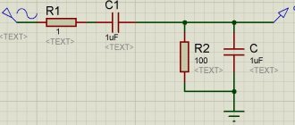
An L-shaped filter is a voltage divider that consists of two components with a nonlinear frequency response (amplitude-frequency response). For this filter, it is allowed to use the circuit and all voltage divider formulas.
It can be represented like this:
If we replace resistance R1 with a capacitor, we get a high-pass filter. You can see a photo of the modified scheme below:
Formulas for calculation:
| U in=U out*(R1+R2)/R2; U out=U in*R2/(R1+R2); R total=R1+R2 R1=U in*R2/U out – R2; R2=U out*R total/U in |
Now let's take a look at how to do the calculation.
▍ Several interesting filter functions
In addition to the cubic one already discussed, you can come up with many other functions for filters based on some mathematical idea.
It also matters how easily (if at all) the inverse function can be calculated. Parabolic, least computationally expensive. If necessary, the inverse function can be found quite simply:
Cubic. The inverse function to it is already a little counterintuitive (and if you are wondering where the trigonometric functions come from here, then here):
Using a 5th degree polynomial, with two zero derivatives at the interface boundaries. The inverse function here is not expressed in elementary functions (and therefore is not given):
Using a 13th degree polynomial - with additional “straightening”:
Using a rational polynomial gives a smoother characteristic and a simpler inverse function than the cubic one:
With a given number of zero derivatives at joining points, a special case of which is the previous function. Its inverse function is also easy to find:
Linearly decreasing on a logarithmic scale:
A smoother version of the previous one with the ability to adjust the “hardness”. Here the inverse function for arbitrary n is not expressed in elementary functions:
With an infinite number of zero derivatives at the joining points, which ensures perfect conjugation. And here the inverse function is easy to find:
With the fastest decaying impulse response - which, with sufficiently large (), allows you to do without a window function at all. The formula itself is obtained by modulating the argument of the cubic function, i.e. :
Here is a special function (error function), defined as an integral of the Gaussian. Instead, you can use the hyperbolic tangent function - the impulse response will also decay quite quickly, although not as quickly as in the previous case. Moreover, for large n, it will visually resemble Linkwitz-Reilly, and this is not at all accidental -
because
Having made a replacement in the function and reduced it, we get nothing more than
DAC and network cable
By analogy with the previous experiment, we will conduct the following experiment. The custom cable remains in the system, but now it will be an intermediary in the electrical circuit for the DAC. All other power components are stock.
It wasn't easy here either. Queen came to the rescue with the song “I Want To Break Free”. And the situation from previous experience was repeated: the main points where the influence of the cable most manifested itself were the lower and upper frequencies. There is clearly less bass with the stock cable. Although now the thought has come to mind that in stock the bass may simply be less deep than with Japanese copper in the power circuit.
A sub is a great helper in such moments. A separately allocated low-frequency section easily allows you to detect changes not only by ear, but also tactilely - with the help of vibrations emanating from the subwoofer. So I'm most likely leaning towards the second option - the bass gets deeper. In any case, there is a change in the sound - and it will be positive if your system does not initially suffer from an excess of bass.
The custom cable also showed an advantage in terms of processing high frequencies - they are more “sparkling” and varied. The imagined scene is clearer and the vocal position is a little more accurate.
To evaluate the changes in this experiment, you may again need audiophile skill, although in a more limited amount than in the case of an amplifier.