Simple 50 W amplifier.
Nikolay Troshin
In this article, I wanted to speculate with you a little, and also share the results of my experiments that I had to conduct as a result of these discussions.
Some time ago I assembled a Linsey Hood amplifier (Class A Ultralinear Amplifier). I never cease to admire this wonderful circuit, which, despite its simplicity, provides high sound quality. However, it also has its own characteristics. As one of my friends aptly put it, this amplifier not only sounds good, but also heats the room well. At 10 W output power, approximately 60 W goes into heat. Large power consumption leads to the need for a powerful power source, which significantly complicates and weighs the design, making it more expensive. The use of small-sized speaker systems (which are currently quite popular), usually having low sensitivity, leads to the fact that 10 W of output power is not always enough to obtain the required volume, especially in the low frequencies. (However, most of the above also applies to other class A amplifiers). As a result, the idea arose to try to transfer this circuit to a more economical class AB. This did not require major changes, but allowed us to get much more
higher power output. The amplifier circuit is shown in the figure below.
Its operating frequency range is no less than 20...30000 Hz. Output power at a load of 8 Ohms is 30 W, at a load of 4 Ohms - 50 W. It was not possible to accurately measure nonlinear distortions (there are no appropriate instruments), but it was still possible to evaluate them. To do this, I assembled a notch filter with a suppression depth of about 70 dB, suppressed the fundamental harmonic with it, and observed what remained at the output of the amplifier with an oscilloscope. At a frequency of approximately 2 kHz and at powers up to 25 W (at a load of 8 ohms) - harmonic distortion is exactly below 0.1%, and maybe significantly lower. I did not measure distortion at a 4 ohm load. The amp sounds very good. A small number of amplification stages helps minimize dynamic distortion.
A few words about the scheme and details. All transistors, except VT1, must be on radiators. On VT2 - 20 sq.cm, on VT3, VT4 - 250 sq.cm (at least). Capacitors must be of decent quality. C5 mica or film. Resistors - any power, except R7 R8, which should be 5 W, and R10, R11 - 2 W. Since there are few amplification stages, the transistors must have a high gain. Not less than: VT1 - 100, VT2 - 80, VT3,VT4 - 100 (at 8 Ohm load) and 150 (at 4 Ohm). With a lower gain of the output stage transistors, the declared power cannot be obtained.
Estimating the gain is not difficult. This technique is described in the article “A Simple Class A Amplifier.” It should be noted that transistors such as KT818, KT819 have a fairly wide range of parameters. I have come across transistors with a gain factor (K. us.) from 25 to 200. Transistors with K. us. 80...100 - about half. With K. us. more than 150 - don't come across often. In the absence of such transistors or unwillingness to measure them, K. us. — it is better to assemble the output stage of the amplifier using 4 transistors (diagram below).
The values of resistors R7, R8 need to be increased by about 5 times, and their power can be reduced to 0.25 W. For transistors KT814 KT815, radiators are not needed in this case. Setting up the amplifier comes down to setting half the supply voltage at the amplifier output (at the negative terminal of C6) with resistor R2, and the quiescent current of the output stage with resistor R9, within 20...50 mA.
IMPORTANT: Before turning on for the first time, you must set R9 to zero resistance. During setup, it may be useful to include a 1 Ohm 5 W resistor in the power circuit. By measuring the voltage drop across it, you can control the current consumption of the amplifier.
As a power source, I used two VT transformers (of different types, which were available) with windings for a current of at least 3 A (in the stereo version, at least 6 A), connected 6 windings of 6.3 V each - in series, diode bridge at 10 A and two capacitors of 4700 μF. You can assemble an amplifier using reverse conduction transistors. To do this, you need to change the polarity of the power supply, all electrolytes and diodes.
In conclusion, a small digression from the topic. I have long been interested in the question of how valid is the opinion that germanium amplifiers sound better than silicon ones. I set up the following experiment: I assembled two amplifiers according to the circuit from the article “Germanium Class A Amplifier,” which worked well. One amplifier is, of course, based on germanium, and the second is completely based on silicon. Gain coefficients were equalized across devices. I connected the inputs of the amplifiers together, and connected a switch to the outputs of the amplifiers, making it possible to quickly connect one or the other amplifier to a three-way speaker system of decent quality. As a sound source I used a good quality CD player and CDs with European recording quality.
We listened to fragments of various works: classical music, opera, good vocals, a modern metal group (melodic compositions with separate sounding instruments and good vocals). I invited three people as listeners, two of whom had a musical education and good hearing.
The results are as follows: 1. All listeners noted the high sound quality of both amplifiers. 2. Neither I nor my listeners noticed any difference in the sound of the germanium and silicon amplifiers. I was also pleasantly surprised by the following. Some time ago one of my listeners was at a concert of that same “metal” band that came on tour to Russia. In his opinion, the sound of my amplifiers is better than what he heard at the concert.
A selection of classic transistor amplifier boards for assembling your own power amplifier
Do you want to assemble a power amplifier for home acoustics with decent sound yourself, but don’t know which option to choose? You need to try a classic class AB transistor amplifier. This is enough power for any acoustics, dynamic sound and low distortion.
Classic transistor amplifiers of class AB, compared to class A, have greater power, lower total cost and acceptable radiators and power supplies. Compared to modern class D, AB has an advantage in price and ease of assembly and configuration.
But in any case, before the finished amplifier, in addition to the boards, you need:
- Power supply (mains transformer + rectifier with power capacitors)
- Acoustic protection on relay (if necessary)
- Soft start for a smooth start (if necessary)
- Volume adjustment (for example, on a double variable resistor)
- Input selector (if necessary)
- Case with cooling radiators
Let's look at the well-known options for class AB amplifier boards on the AliExpress site.
X-One
Find out the price
The selection opens with an option from ZeroZone with a low power of 30 W - X-One. The rectifier and power supply capacitors of 10,000 uF are already installed on the board, and there is also protection for the acoustic output on a relay and a UPC1237 chip. I like such combined solutions; it’s easy to install everything on board and there are no long wires.
Power transistors are used Hitachi J2SJ555 2SK2586.
The dimensions of the board are 119x76.5 mm, a transformer with a secondary winding of 22-0-22 V is required.
This lot has a choice of:
- Only printed circuit boards 2 pcs.
- Circuit boards and a set of parts for do-it-yourself soldering
- Ready and tested boards
NAP140
Find out the price
Naim NAP140 clone of an interesting English amplifier model from the 90s from the AIYIMA brand. This lot contains a kit for self-assembly: printed circuit boards for two channels and parts. Assembly is not difficult. You must remember to set the required quiescent current of the transistors for your power supply.
Power 80 W at 8 ohms. Bipolar power supply up to 40 V DC (transformer 28-0-28 V).
Board dimensions 123x93 mm. Powerful SANKEN 2SC2922 transistors are used.
NAP250
Find out the price
Continuation of English history. Clone of the NAIM NAP250 amplifier. Compact and simple.
Small boards 71x48 mm, one pair of 2SC5200 output transistors (the originals promise!). Quiescent current 10-20 mA.
Output power RMS 80 W into 8 ohms. The board is powered from 15 to 40 V DC. Output THD + N = 0.001% - 0.03% at 30 W.
The lot contains a kit for assembling an amplifier or assembled and configured boards.
MX50 SE
Find out the price
The classic 100 W option is the MX50 SE. The boards are small, 76x73 mm. Power supply: 15-45 V bipolar DC voltage. A transformer with a secondary winding of 24-0-24 V is recommended.
Output pair of transistors KTB817, KTD1047. The kit includes gaskets to isolate the transistors from the radiator.
The output parameters are quite good for such a simple circuit: THD + N = 0.002% 20 Hz-20 kHz 10 W RMS 8 Ohms.
The lot contains a kit for assembling an amplifier or assembled and configured boards (2 pcs.).
XA50
Find out the price
A clone of the famous Musical fidelity XA50 amplifier. With two pairs of output transistors installed horizontally. Board dimensions: 168x78 mm.
I liked this version because it has a rectifier and 4700 uF power supply capacitors on the board itself.
A transformer with a secondary winding of 24-0-24 V is recommended.
The kit includes stands for the board and gaskets to isolate the transistors from the heatsink.
L25
Find out the price
For those who don't think 100 W is enough, the L25 model from LJM has two pairs of output transistors and 250 W at 8 Ohms. Power supply from 24 to 70 V!
Output transistors KTB817, KTD1047, drivers 2SA1186, 2SC2837. Quiescent current 20 mA.
To obtain the declared power you need a powerful power supply.
The lot contains a pair of assembled and configured boards with aluminum adapter corners for mounting on a radiator. Radiators at maximum voltage require about 2 kg per channel.
Driver board UPC2581V
Find out the price
Next is the option with the NEC UPC2581V driver and output transistors: NJW0302G + NJW0281G.
This lot has several options for the set (I recommend taking it without a radiator, using your own):
- DIY soldering kit
- Assembled board
- DIY soldering kit + cooling radiator
- Assembled board + cooling radiator
For power supply you need a mains transformer with a secondary winding of 18 to 30 V with a midpoint.
- Board dimensions: 155x120x50 mm
- Load impedance: 4-8 ohms
- Quiescent current: up to 60 mA
- Maximum declared power: 150 W per channel
Review of this board.
Driver board LME49810
Find out the price
The selection also ends with an option with a driver (here on LME49810) - well-designed and powerful. The power is as much as 300 W at 8 ohms! One card per channel.
Wide range of bipolar board supply voltage: from 20 to 100 V. At the output, Toshiba 2SA1943/2SC5200 power transistors are located horizontally. Quiescent current 60 mA.
The board is large (power, 3 pairs of output transistors) 215x93.5 mm. The output is 0.007% THD+N.
There was a place on the board to protect the acoustics on a powerful relay and UPC1237.
I hope the selection of transistor amplifier boards for a DIY audio project was useful and you will choose an option to suit your taste (hearing) and budget.
Happy shopping! Don't forget to apply AliExpress coupons and discounts.
Coupons for the Russian Federation and CIS countries (will start working on September 27 from 10.00 Moscow time)
TRENDSALE100 – 100 from 800 RUR TRENDSALE200 – 200 from 1,500 RUR TRENDSALE350 – 350 from 3,000 RUR TRENDSALE500 – 500 from 5,000 RUR TRENDSALE700 – 700 from 7,000 RUR TRENDSALE1500 – 1,500 from 16,000 RUR TREND SALE1700 – 1,700 from 18,000 rub. TRENDSALE2400 – 2,400 from 30,000 rub.
The first transistor ULF
And I built it in 1962 according to the scheme of H. Lin [1]. There was nothing to choose from for output transistors - only P4 were available. The working amplifier was not excited, but at high frequencies (after 10 kHz) the current consumption increased by 3 times due to the poor frequency properties of transistors P4.
The sound of the amplifier was no worse than that of tube devices of that time (at least when compared with the Druzhba radiogram), and the power was greater than that of all radio receivers released up to that time.
Rice. 1. Schematic diagram of a UMZCH on germanium transistors, 20 W at 4 Ohm.
However, another drawback also emerged: weak suppression of rectifier voltage ripples when powered from the mains. But since its supply voltage was about 30 V, the current consumption was no more than 1 ... 1.5 A, I easily overcame this drawback with the help of a transistor voltage stabilizer. Then more advanced transistors began to appear: P308, P605, etc.
The power of the amplifiers began to increase, and along with it the dimensions of the radiators for cooling the ULF output transistors and the stabilizer. Problems arose with self-excitation (transistors became more high-frequency), often leading to burning out of powerful and expensive transistors.
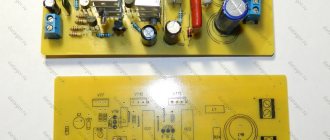
Converter circuit for cars
- Supply voltage: 12.5V (car battery)
- Output voltage: 40V (1×15 turns and primary 2×5 turns)
When testing the converter, connect a resistor with a resistance of 16 Ohms and the current consumed by the converter will be about 3 A, and the current flowing through this resistor will be 1.2 A. In this case, the operating frequency of the inverter: 55 kHz, transformer core ETD44-3F3.
Why is everything built on transistors? There are no amplifier integrated circuits with a power of more than 50 W that have a voltage boosting system. Even TDA1560, TDA1562, TDA8571 will not provide equal power.
But if you already have a 12-220 Volt converter, you can change its transformer and connect a higher power chip to it, even a TDA7294 or any others, removing at least 70 W.
As for the 50W, it is obtained with a speaker coil impedance of 8 ohms. Increase the voltage to 55-60V, the amp should be able to handle it and the power will be much greater. Also, instead of 2200uF output (for 8 ohms), give 4700uF for 4 ohms.
With these transistors, the circuit will squeeze out 100 W. You just need to convert the amplifier circuit and converters to a higher voltage. Radiators for those 100 W also need more.
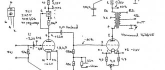
Voltage stabilizer circuit
Fast acting overcurrent protection was required. The diagram of one channel of a two-channel amplifier I built in 1968 is shown in Fig. 1. The amplifier delivered 20 watts into a 4 ohm load and sounded great. It was powered by a stabilizer with electronic protection on a tunnel diode (Fig. 2).
Rice. 2. Voltage stabilizer circuit with electronic protection based on a tunnel diode.
Amplifier improvement
The diagram of the final version of the UMZCH is shown in Fig. 4. Transistor VT9 (MP25) controls the current through output transistors VT7 and VT8.
Rice. 4. The final, modified version of the UMZCH circuit using transistors.
Rice. 5. Continuation of the UMZCH circuit from Figure 4.
If its specified value is exceeded, the trigger on the tunnel diode VD5 is activated, and relays K1, K2 turn off the power to the amplifier. Button SB1 resets the trigger to its original state.
Unfortunately, noticeable ripples of the supply voltage “creep” through the output, so the amplifier must be powered from a stabilized source.
I liked the sound of both this amplifier and the amplifier in Fig. 1 more than the tube ULF radio “Symphony-2”, the best product of Soviet industry in those years.