The world's first magnetic pickup was designed by the talented engineer Lloyd Loehr, who worked at Gibson in 1924. The first samples of electrified instruments did not produce the desired effect among musicians, and mass-produced electric guitars appeared only in 1931. The electric guitars of the Electro String Company, which, by the way, looked more like a banjo, were jokingly nicknamed “frying pan” by the musicians.
The principle of operation of a magnetic pickup, now familiar to anyone who has taken a school physics course, has not changed to this day.
The advent of the guitar amplifier
The appearance of the guitar amplifier was made possible thanks to the very idea of increasing the volume of the guitar. Guitarists playing in ensembles were forced to increase the volume of their instruments so as not to get lost in the overall sound picture. Initially, there was no separate amplifier for an electrified guitar, and any amplifiers that were at hand were used. Experimenters of that time, gradually gaining experience, realized the promise of industrial production of guitar amplification equipment.
Over time, from small companies huddled in a garage or store basement, transnational companies were formed - manufacturers of professional musical equipment, proudly bearing the names of their “founding fathers.” In the world of guitar amplifiers, the words Fender, VOX, Marshall, Mesa Boogie, Orange have become household names, and the sound of these amplifiers has become a standard, which other manufacturers emulate and try to surpass.
Types of Guitar Amplifiers
- tube
- transistor.
- hybrid.
Guitar amplifiers can also be made in several versions:
- Guitar combo (the amplifier itself is built into the speaker system).
- Guitar amplifier head with speaker system (cabinet).
- Guitar power amplifier (in this version, the preamplifier and power amplifier block are made as a separate device).
Each version of a guitar amplifier has its pros and cons: the classic versions of “that same sound” are just guitar amps or guitar amplifiers with cabinets (they are also called a guitar stack), but they are usually very bulky and inconvenient to transport. In contrast, rack units take up less space and can be wired in different ways, but they don't look "cool" on stage during concerts.
Regardless of design, guitar amplifiers come in different capacities. This could be a 10-15 watt unit (often such devices are used in not very large recording studios, when volume is not the most important parameter) and a 50-100 watt tube monster (it is these stacks and combos that can be seen at large stadium concerts on stage for the guitarist's back). Today there are even 1-watt devices for the home, for the family, so to speak.
Please read the user manual carefully before using any electrical device. Before connecting for the first time, I would recommend checking whether everything is in order with the amplifier, whether the speaker is connected to the amplifier output, and whether there is any structural damage to the case. It is necessary to clarify the operating voltage of the amplifier (amplifiers and combos designed for the American network operate from 110 volts; they can only be connected to our network through a special step-down transformer).
Also, it is advisable that the network be grounded, otherwise you risk getting an electrical injury (the strings of an electric guitar through the metal bridge are in contact with the grounding of the electrical circuit, and if you hold the strings with one hand and the radiator with the other, you can get an electric shock), and extraneous noise will leak into the sound . If this is a tube combo or amplifier, you need to make sure that during transportation the radio tubes have not jumped out of the contact panels (it is enough to look into the amplifier or combo through the technical holes and, if necessary, correct crookedly installed radio tubes).
Before turning it on, I would recommend turning the overall volume down to zero, and setting all other controls to the 12 o'clock position (this does not mean the division of 12, but the conventional clock dial). From this position it is easiest to control the sound. In a tube guitar amp, you usually need to press 2 switches (power and stand by) to turn it on. Moreover, first you need to turn on the power and then after 2-3 minutes stand by; you need to turn off the amplifier or tube guitar combo in the reverse order (stand by is turned off first and then power).
In addition to the switches on the front panel of the guitar amplifier, there are overall volume controls, high, mid and low frequency controls, and a gain control. Sometimes there is a presens control (more precise focusing of high frequencies). There is also a channel switch on the front panel (if the amplifier is more than single-channel).
On the back panel of the guitar amplifier there are: an output to the cabinet (you need to remember that you can connect to the amplifier to a cabinet matched in resistance), outputs to the effects loop (when you can connect different, usually spatial effects or processors to the amplifier), an output for connecting a control pedal (them you can switch amplifier channels or turn on the reverb effect if it is built into a guitar combo) sometimes on the rear panel you can find a cabinet emulation output (this output can be connected directly to a mixer or recording device).
Modern industry offers guitar amplifier combos with built-in effects. Such combos are convenient due to their compactness and mobility. There is no need to buy separately a bunch of different guitar effects, connecting wires, and power supplies for effects. On my own behalf, I can add that the sound of expensive units will be at the same level, and as a result, the price will be the same.
Unfortunately, Chinese guitar amps cannot boast of this.
When is a tube better than a transistor?
When is a tube better than a transistor? Author A. Likhnitsky
Preamble. For years, transistor amplifier manufacturers have fooled audiophiles by offering them plausible explanations for why an old amplifier model should be replaced with a new one. Let me briefly recall these explanations: - harmonic distortion is too high (in new amplifier models, distortion has been reduced to 0.0001%); — the damping coefficient is small (the damping coefficient has reached 1000); — the band of reproduced frequencies is not wide enough (the band was expanded to 5 MHz); — amplifiers limit the speed of signal change (the inscription “High Speed Amplifier” appeared on the front panels of new amplifiers); - the loudspeaker requires more current (and many output transistors connected in parallel provide an amplifier output current of 100 A). This list could be continued.
While it was possible to maintain faith among audiophiles in all these technical “troubles,” revival reigned in the amplifier market. However, the gold mine seems to have dried up. It became clear to many that what was written in advertising should be treated with caution and that one could only trust one’s own ears or at least the ears of qualified experts. After the games of superparameters, the era of subjectivism began. By the mid-80s, modest “by the numbers” tube amplifiers came into fashion. Please note that none of the above recipes for good sound in tube amplifiers have ever been implemented. This is probably why many audiophiles have a suspicion that transistors bring “damage” to musical sound and that even a simple home tube amplifier can remove the transistor “evil eye” and “clean” previously made transistor and even digital recordings from it.
Does a lamp have advantages over a transistor, and if so, under what conditions do they appear?
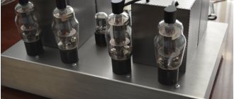
In difficult moments of presentation - and, of course, there will be them - the Objectivist (O), already familiar to the reader, will help me. In order not to immediately fall into mysticism, let us consider at the physical level the differences between a lamp, field-effect and bipolar transistors. A lamp (let’s take a triode as an example) can be considered as a “conductor”, which consists of electrodes thoroughly cleaned of oxygen - anode and cathode - as well as a vacuum gap between them filled with charge carriers - energetically excited free electrons. The anode current carried through the vacuum by free electrons is controlled by the voltage between the grid and the cathode. The amplifying properties of the triode can be characterized by the slope of the characteristic, that is, the ratio of the anode current increment to the grid-cathode voltage increment (at a constant voltage at the anode). The independence of the slope from the electrical modes of the lamp serves as an indicator of its linearity. It is especially important that the slope of the triode characteristic depends little on the anode current (in most cases it is proportional to the third root of the value of this current). The influence of the input characteristic of the lamp on linearity can be neglected, since in the negative grid bias mode there is no current in its circuit.
The interelectrode capacitances are constant and do not depend on the electrical modes of the lamp. It is also important that the main parameters of the lamp do not depend on the temperature of the anode or, in other words, on the power released on it. And another important advantage of the triode is its low internal resistance, which in the optimal mode of using the lamp is approximately half the load resistance. The dependence of the internal resistance of the lamp on the anode current is inverse to the dependence of the transconductance of the triode on this current, therefore, in a mode in which the load resistance is greater than the internal resistance, the gain of the lamp is practically independent of the anode current.
A field-effect transistor can also be considered as a “conductor”. The conducting part of the transistor is a channel in a crystal of ultra-pure silicon, the type of conductivity of which (p- or n-) is determined by an insignificant admixture of indium or arsenic. Depending on the conductivity type of the transistor, charge carriers move in the channel: free electrons or “holes” (spaces in the crystal lattice not filled with electrons). As with a tube triode, the current at the output of the FET (drain current) is controlled by the voltage between the gate and source. The amplifying properties of a field-effect transistor (like a lamp) can be characterized by transconductance (that is, the ratio of the drain current increment to the gate-to-source voltage increment). A field-effect transistor has a more pronounced nonlinearity than a lamp. For almost all types of field-effect transistors, the transconductance increases in proportion to the square root of the drain current. Like a lamp, there is no current in the control circuit (gate circuit), so the nonlinearity of the input characteristic of the field-effect transistor can be neglected.
The situation is somewhat worse with interelectrode capacitances. The most important drain-gate capacitance depends on the voltage acting between these electrodes. The most disappointing fact is the high sensitivity of the drain current and slope of the field-effect transistor to changes in the temperature of its crystal. This sensitivity is explained by the increase in charge carrier mobility with increasing temperature and is usually characterized by the gate-to-source voltage temperature coefficient (that is, the increase in gate voltage that is necessary to maintain a constant level of the transistor's drain current when the temperature of its crystal increases by one degree). Depending on the mode in which the field-effect transistor is used, the temperature coefficient can take a value from 2 to -3 mV/deg [1]. The worst thing is that the temperature of the transistor crystal, although with inertia (determined by the thermal time constant of this transistor), keeps pace with almost all changes in the instantaneous power dissipated in the transistor, but we will talk about the negative value of this a little later. In addition to static induction transistors, other types of field-effect transistors have an internal resistance much greater than the load resistance.
A bipolar transistor is also a kind of “conductor”. However, the physical processes associated with the passage of current in it are fundamentally different from those that occur in lamps and field-effect transistors. The first difference is that charge carriers, and they are electrons or holes, have to overcome two barriers (pn junctions): emitter - base and base - collector, that is, move twice from a crystal lattice of one type to a lattice of another type. The second difference is in the principle of controlling the collector current. The magnitude of this current depends on the amount of so-called minority carriers “injected” from the emitter into the base, which “wander” in it until they are drawn in by the strong electric field of the collector, biased in the opposite direction with respect to the base. The injection of minority carriers into the base is controlled by forward biasing (in other words, slightly opening) the base-emitter junction of the transistor. The amplifying properties of a bipolar transistor can also be characterized by transconductance (that is, the ratio of the collector current increment to the base-emitter voltage increment). According to the theory, the transconductance of a bipolar transistor is approximately proportional to the collector current, so it has a more pronounced nonlinearity than a field-effect transistor. Unlike a lamp and a field-effect transistor, the nonlinearity of the transconductance of a bipolar transistor should be added to the nonlinearity of its input characteristic. And this is understandable, since even in appearance it differs little from the current-voltage characteristic of a forward biased diode.
The same thing happens here with the interelectrode capacitors as in a field-effect transistor. The most important capacitance of the collector-base junction of a bipolar transistor depends on the voltage acting between these electrodes. In a bipolar transistor we are also faced with the high sensitivity of its parameters to changes in the temperature of the crystal. Namely, the temperature coefficient of the base-emitter voltage is -2.2 mV/deg, and the transistor current gain increases by 2-3%/deg. As in a field-effect transistor, the temperature of the bipolar transistor crystal with inertia (determined by the thermal time constant) keeps pace with changes in the instantaneous power dissipated in the transistor. The internal resistance of bipolar transistors also leaves no hope - it is always greater than the load resistance. The most important and completely objective differences between a lamp, a field-effect transistor and a bipolar transistor are grouped in the table.
There are three main differences. A bipolar transistor differs from a lamp in the thermal sensitivity of its main parameters, greater nonlinearity of input and output characteristics (a field-effect transistor occupies an intermediate position in this series); and besides this, a lamp (triode) is superior to a transistor in terms of the convenience of matching its internal resistance with the loudspeaker. From my point of view, all this is quite enough to prefer a tube amplifier to an amplifier based on field-effect transistors, and the latter to an amplifier based on bipolar transistors.
Objectivist: Your point of view does not sound very convincing, because there is a radical remedy against the shortcomings of transistors you noted - negative feedback (NF). Better look for the reasons for the bad sound of transistor amplifiers in their circuits.
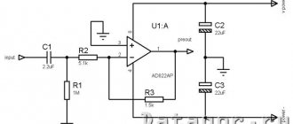
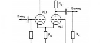
Author: I agree. Let's compare a traditional and well-proven amplifier based on tubes (see diagram in Fig. 1) and an amplifier based on bipolar transistors that is quite simple to consider (see diagram in Fig. 2).
The main thing that distinguishes a tube amplifier is the output transformer, which serves to convert the low impedance of the speaker into the optimal load impedance of the output tubes. In a transistor amplifier, optimal matching is possible without the use of a transformer. It is difficult to do without a transformer in a tube amplifier, if only because it ensures symmetrical operation of the output stage in the push-pull mode. In a transistor amplifier, this mode can be achieved by connecting transistors of different conductivity types in series. Unfortunately, a lamp with the opposite type of conductivity has not yet been invented.
O.: See! A transistor amplifier is no more complicated than a tube amplifier, and most importantly, it does not have an output transformer, so if the transistors themselves do not cause sound “damage” that is difficult to objectively analyze, then the transistor amplifier should sound better than a tube amplifier.
A.: Do not rush to conclusions, but take a close look at both diagrams above in the text. The fundamental difference between a tube amplifier and a transistor amplifier is the lack of feedback in it. In a transistor amplifier, each transistor and the amplifier as a whole are covered by OOS. Indeed: T1 is covered by local serial feedback in current through RZ, T2 is covered by local feedback in current through R6, output transistors TZ and T4 are covered by local feedback in current through resistors R7 and R8 with also serial feedback in voltage through the speaker resistance; the amplifier as a whole is covered by a common series OOS in terms of voltage through a divider of resistors R4 and RЗ (Fig. 2).
A.: Although I see only benefits from using OOS, I am ready to offer you a circuit of a transistor amplifier in which there is no OOS, an example of the circuit is shown below.
A.: I don’t want to be petty, but every bipolar (or field-effect) transistor has a consistent current feedback, which is formed as a result of a drop in part of the signal at the internal resistance of the emitter (source) of the transistor. These connections could be neglected if the proposed scheme did not have more serious shortcomings. The first is an order of magnitude larger (compared to a tube amplifier) and spectrum-unfavorable nonlinear distortions. If a tube amplifier is not brought to clipping, the harmonic distortion at its output does not exceed 1-3%, and the 3rd harmonic dominates in the composition of this distortion; the second, as a result of the “push-pull” principle, is compensated, and the higher harmonics are attenuated. In the amplifier shown on the left in Fig. 3, the combination of nonlinearities of the input and output characteristics of bipolar transistors causes the formation of a whole spectrum of harmonic, and in the case of a complex signal, significantly higher-power intermodulation distortions of higher orders. Specialists are well aware that there are no effective means for reducing higher-order nonlinear distortions. The use of OOS even worsens the situation, since with its help lower-order distortions are converted into higher-order distortions. The presence in a musical signal of even small-sized higher-order intermodulation products gives the listener a feeling of “metallicity,” harshness, roughness, and cloudiness of the sound; most often, such a sound is simply called unnatural. The second drawback of the proposed circuit is the dependence of the amplifier parameters on the instantaneous temperature of the transistor crystals. It is not difficult to verify this by assembling the proposed circuit and then observing how the current in the transistors and the voltage at the output of the amplifier flow, especially if you blow lightly on the assembled circuit. You can stabilize the output of the amplifier by using the so-called servo drive (which, by the way, is a type of OOS), but how to solve the problem of distortion, which is usually called “thermal”?
Thermal distortion [2] occurs when a change in the signal (voltage and current) at the output of a transistor is accompanied by a change in the instantaneous power dissipated in it and, as a result, the instantaneous temperature of its crystal changes. Which causes the following phenomena: in the process of amplifying a musical signal, the current gain of the output transistors smoothly (due to the inertia of thermal processes) changes by 20-30%. These changes, in turn, cause infrasonic intermodulation distortion in the amplifier, to which the listener's ear is extremely sensitive. Another manifestation of thermal distortion is explained by the fact that the base-emitter voltage depends on the temperature of the transistor crystal. It turns out that the change in voltage (and current) at the output of the transistor, which represents the change in the power dissipated in it, is first converted into a change in the temperature of the transistor crystal, and then into a change in the base-emitter voltage, which, in turn, is again converted into a voltage ( and current) at the output of the transistor. As a result of these transformations, in each transistor of the amplifier (and especially in the one shown in Fig. 3), nonlinear electrothermal negative feedback arises, which, if local current feedback is not used, causes in the region of low audio frequencies (below the frequency of 150 Hz) a decrease in gain by 10-15 dB, as well as an increase in harmonic and intermodulation distortions, which reach 10-15%.
The third disadvantage of the amplifier circuit is shown in Fig. 3 is its unacceptably high output impedance. If the output impedance of the amplifier is greater than the impedance of the loudspeaker, the sound of the latter is characterized by increased boominess and prolonged bass. In this regard, international hi-fi standards recommend as a “minimum requirement” that the output impedance of the amplifier should not exceed 1/3 of the impedance of the loudspeaker. It is possible to ensure the required output impedance of an amplifier using transistors (except for those cases when field-effect transistors with static induction are used as output ones) by connecting a resistor in parallel with the loudspeaker or by covering the output stage with negative voltage feedback. I think that a transistor amplifier cannot do without OOS, since in order to provide even modest values of nonlinear distortion and acceptable output impedance, a transistor amplifier must at least have deep local OOS.
O.: Why do you so persistently proclaim the undesirability of using OOS in amplifiers, while you are even ready to put up with such an anachronism of tube amplifiers as an output transformer? What bad thing can you say about OOS after 60 years of its successful application in many fields of technology?
A.: We’ll talk about how OOS behaves in amplifiers a little later. First, let's look at some of the effects caused by passing a music signal through conductors [3], including capacitors, tubes, and transistors. As I already told you in our recent dispute (AM No. 4(5) 95, p. 5), the signal in a conductor is split into several components, which propagate through it at different speeds.
The so-called multipath propagation of the signal is observed. The passage of a signal through a conductor can be represented using a signal graph (see Fig. 4a). On it A - signal transmission at the speed of light and with an almost constant amplitude; B, C, D - signal transmission with different delays and different coefficients, say, two orders of magnitude less than along path A. It is unlikely that when a sinusoidal signal passes through such a conductor, you can notice any changes at its output. Changes could be detected in the music signal, but such measurements have not yet been learned to be made.
O.: I wonder why the wire reacts to a music signal and does not respond to a sine signal?
A.: The reason is that musical signals differ from sine signals by much greater variability [4]. Unexpected amplitude bursts and dynamic transitions from one harmonic composition to another are most important in the perception of music. They give the sound liveliness and energy. During multipath propagation of a signal in conductors, in particular in amplifier circuits, signal sections with increased variability are destroyed and their phase destructuring occurs. In this sense, we can talk about the existence of filters that are not indicated on the amplifier diagram, limiting or converting the variability of the signal. A special case of the variability filter indicated in the diagram is a conventional high-pass filter. Yet, if the filter is invisible and does not affect the spectral composition of the signal, it is not so easy to detect using standard measurement methods. If standard methods are not ready to “digest” musical signals, then our brain copes with this task quite satisfactorily. When you compare the sound of the cables, the first thing you notice is the difference in clarity of detail, intonation pattern and dynamics. Frequency regions in which signal variability is poorly transmitted sound sluggish, inexpressive, quiet, and the region in which variability is clearly audible begins to dominate, although an apparent rise is not detected in the frequency response.
A: It seems to me that you are again interested in cable testing. Better yet, tell us why OOS is harmful?
A.: Yes, perhaps. But it is the considerations I have expressed that will help us understand this issue. Let's depict a certain hypothetical amplifier with negative feedback in the form of a signal graph. In this amplifier, the forward branch has two signal paths: one with instantaneous transmission A, inverted in phase, and the other with transmission B (where |B|<<|A|) delays the signal for a time (tau). Transmission feedback (betta) returns the signal instantly. The transmission coefficient through this hypothetical short-pulse amplifier at the moment t=0 can be represented by the first relation. And at the moment of coincidence t and tau the second relation.
The electrical processes in the OOS loop do not end there. The fact is that the last response through the OOS returns again to the input of the amplifier and causes an additional response at the moment 2tau:
Having received an additional delay, the signal again enters the amplifier input, and so on. As a result, instead of two responses to one pulse at the output of an amplifier with OOS, we will have an infinite number of them with an amplitude that decays over time:
It turns out that with an infinite number of rounds of the loop, the signal is quite noticeably blurred in time. In the case of a general feedback loop, we can talk about a washout time of 100 ms or more, and therefore the most noticeable consequence of the effect of general feedback on the sound is a deterioration in the dynamics and a weakening of the energy of the sound of the music. It is now possible to understand why local OOS behave better in the presence of sound than general ones. A shorter signal path in the loop, as a result, smaller delays - as a result, a shorter period of signal blurring. However, do not delude yourself: in this case, the signal is destroyed, and its most volatile areas suffer. The described phenomena are aggravated when, above a certain frequency (the so-called dominant pole), the loop gain begins to fall with a slope of 6 dB/oct [5]. Let me remind you that the frequency of the dominant pole in most amplifiers with deep feedback is located in the frequency range from 2 to 5 kHz, and in operational amplifiers on microcircuits from 50 to 300 Hz.
The fact that a decrease in the frequency of the dominant pole and its entry into the audio range has a bad effect on sound was first noticed by J. Lochstroh and M. Othala (1973), however, they explained this phenomenon by the formation of TIM distortions [6], introducing a misconception not only among audiophiles, but also among developers of audio amplifiers. In fact, this phenomenon can be explained in the light of the concept of signal blurring by the OOS loop. The fact that the OOS begins to function worse when the loop gain depends on the signal frequency can be visualized by considering the operation of an amplifier loaded onto a real loudspeaker, the output impedance of which is simulated using the OOS.
If a flash of tone (Fig. 5a) with a filling frequency equal to the frequency of the main resonance of the loudspeaker is applied to the input of such an amplifier, then, trying to reproduce it at the output, the amplifier will generate a signal in the forward path of the OOS loop (controlling the currents of the output transistors), which has the form shown in fig. 5 B. In this figure, circled is a jump in the phase of the control signal, which occurs in response to the loudspeaker attempting to continue its oscillations at the resonant frequency. Comparing Fig. 5a and fig. 5b, you can see that the variability of the control signal (inside the feedback loop) should be greater than that of the signal acting at the input of the amplifier. And everything would not be so bad if the signal variability was not limited by “invisible” filters inside the OOS loop. However, precisely because of this limitation, at the moment the tone flash stops, the controllability of the amplifier is disrupted, and the signal at its output will depend on the signals stored in the memory of the OOS loop, but which have already passed through previously. This zone of not entirely predictable amplifier behavior is circled in Fig. 5th century Lack of bass clarity and purity is what the owner of an amplifier (no matter tube or transistor) whose output impedance is simulated using OOS ends up with.
O.: I listened to you for a long time and finally realized that you are a real objectivist. After all, first you explain everything and after that you tell how it should sound.
A.: Yes, many years ago I had to observe the described phenomena on a prototype of the Brig amplifier. Then I could not figure out why the end of the tone flash in the zero area was distorted, but it was at that time that I took the first step towards subjectivity. I trusted my feelings when I heard how connecting a 4 ohm resistor parallel to the output of the amplifier (and at the same time to the loudspeaker), contrary to the prevailing ideas of that time, improved the sound of the bass. I only managed to understand what was going on 20 years later. In conclusion, we need to dwell on the questions that the Objectivist forgot to ask. Is there still a noticeable difference in the sound of tubes and transistors? How can we explain that a simple home amplifier using tubes “corrects” studio recordings made using transistor equipment? These questions, apparently, will hang in the air for a long time and will not receive a comprehensive answer.
Firstly, it is very difficult to set up a pure experiment in which, without changing the electrical circuit, the lamp could be replaced by a transistor. In addition, lamps are different from lamps (the same can probably be said about transistors). For example, lamps of the same type, completely identical in design, but manufactured by different companies, do not sound the same. It is unlikely that the vacuum in the GDR is worse than in other countries, but it is the tubes manufactured by the RFT company that sound almost the same as transistors. I think the reason is that the materials used to make the lamp electrodes are poorly purified from impurities. Let them say that I am fantasizing, but lamps with a large anode have a more attractive sound than those with a small one; the sound character of the latter is harsher and shrill. This can be easily verified by replacing the ECC83 tube in the preamplifier with another of the same type, but with a larger (or smaller) anode [7]. A small lamp anode is a small transistor crystal: perhaps this is the answer to the phenomenon? Or is the reason due to a silicon crystal “poisoned” with arsenic or indium? And pn junctions in this crystal, presumably, also mean something? But all this is in the realm of speculation. There is no reliable data about the specific sound of tubes and transistors, as well as explanations for it.
Now about “tube cleaning” of transistor recordings. I think that there is an effect of harmonization of the “recording - playback” path here. An amplifier using tubes with a large anode quite often highlights and even “ennobles” the frequency region from 400 to 600 Hz, thus returning to the listener the “lost” soundboard of a violin, the foundation of a singing voice, and even the tutti richness of a symphony orchestra. There is a harmonization of the tract in terms of tonal balance. Another feature of tube amplifiers is the pleasant integration of their sound, thanks to which transistor recordings seem to be cleared of roughness that irritates the listener.
This effect can indeed sometimes be observed, but at the same time subtle details and strokes disappear from the recording. From my point of view, the expressiveness of the sound is simply replaced by greater comfort. But it is quite natural that the listener wants to have a certain balance between the elaboration of fine details and the integration of sound, which musicians often call “coherency”. By the way, with the “live” sound of music, such a balance is achieved by a specially selected ratio of direct sound and reverberation in the hall. However, why change anything in the natural balance? As it turns out, transistor recordings actually add additional harshness and roughness to the music being played, especially in the upper register. The reason, as we have already shown, is harmonic and intermodulation distortions of higher orders. It is therefore not surprising that the listener prefers a more integrated sound character of recordings than during “live” performance.
And yet, for the “cleaning” of transistor sound recordings that we have considered, it is not at all necessary to use lamps. From my personal experience it follows that a similar effect can be obtained by skillful selection of interconnect and output cables. A fairly convincing result is obtained if you use OFC type wires. However, if the recording lacks dynamics, clarity, spatiality and naturalness, then neither lamps nor cables will help. The signs I listed of good sound in such a recording are apparently lost forever.
Conclusion
So does the phenomenon of transistor and tube sound really exist? I think that on an intuitive level one can give preference to a lamp, as a vacuum conductor, over a transistor with a crystalline structure. However, apart from unconvincing listening results, there is no evidence that a transistor, when used correctly, sounds worse than a lamp.
At the same time, among the developers of “high-end” amplifiers, the opinion gradually formed that it is not a matter of transistors at all, but of the OOS, without which not a single amplifier with transistors can do. It became clear: OOS destroys the music signal.
This explanation came when it became clear that delayed copies of the signal circulate in the OOS loop. The reason for the formation of these copies was complex physical phenomena in conductors and other elements used in the amplifier.
Paradoxically, the harm from OOS in amplifiers turned out to be greater than the use of such an anachronism as an output transformer.
If the amplifier using tubes is made in a circuit design close to transistor amplifiers (that is, you start using OOS), then the advantage of tubes over transistors will be negated.
An indirect confirmation of this can be considered the gradual disappearance from the audio market of complex tube amplifiers of the “OTL” type (with a transformerless output) at a price of 4 to 10 thousand dollars and the simultaneous appearance on it of simple triode amplifiers with a transformer output at a price of more than 200 thousand dollars.
I think that if it is ever possible to completely get rid of negative feedback in a transistor amplifier, the tube barrier will be overcome.
[1] The field-effect transistor can be set to a mode in which the temperature coefficient is zero.
[2] For more information about thermal distortions, see the article in the journal “Techniques of Cinema and Television”, 1987, No. 6, p. 10-17.
[3] We should not even talk about the conductor itself, but about almost invisible, but physically existing structural barriers in the conductor, as well as barriers at the junction of the conductors.
[4] For specialists: signal variability has a strict mathematical interpretation and means the current integral of the modulus of the second time derivative of the signal, viewed through a sliding “time window” of subjective perception (about this, see: S. Mazon, G. Zimmerman. Electronic signal circuits and systems. M., 1963, pp. 246-250, etc.)
[5] Smooth (with a slope of 6 dB/oct) attenuation of the loop gain at high frequencies is necessary in order to ensure stable operation of the amplifier with OOS.
[6] TIM (Transient Intermodulation distortion) arise as a result of a “hard” limitation of the rate of change of the signal in the section of the direct branch of the OOS to the link that forms the dominant pole in it. Musical signals whose speed is so high that it would be limited in a standard amplifier with OOS do not exist in nature.
[7] The ECC83 double triode is produced in three design options, with anode heights of 11, 14 and 16 mm. A. Likhnitsky. AM No. 1 / 1996.
Bravo, Mr. Likhnitsky. Very professional and very detailed. And the judgments are quite cautious, and most often neutral. However, I would not apply such concepts as “sounds” to specific lamps. In addition, I consider some conclusions not obvious, especially with regard to environmental protection. Fast electricity, very fast. They say that signals travel at the speed of light, which is quite significant, especially over short distances. Therefore, swings, splitting and duplicates of signals within the OOS are extremely insignificant and extremely fleeting. It is unlikely that it is rational to consider a short connection using wave concepts from the theory of long lines. Based on materials from the network, I prepared an article
Evgeny Bortnik, Krasnoyarsk, Russia, June 2016
The main differences between tube and transistor guitar amplifiers
A transistor guitar amplifier is relatively cheap to make, lightweight, and its low output impedance makes it easy to pair with any low-impedance speaker. The radio components from which it is made do not require periodic replacement, the transistor guitar amplifier is not afraid of the “microphone effect” (an undesirable phenomenon in which some part of the electrical circuit perceives sound vibrations and vibration like a microphone). In addition, transistor guitar amps often have a headphone output built in, so you can play the guitar without disturbing anyone in the first hour of the night.
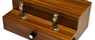
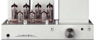
A tube guitar amplifier, unlike a transistor one, has an output resistance of up to several tens of ohms, so the sound is affected by both the quantity and quality of the output stage tubes and the quality of the output (matching) transformer (the cost of the output transformer alone can be commensurate with the price of an average transistor amplifier ). In addition, unlike a transistor amplifier, a tube unit is repairable even in the field (while a transistor amplifier can be repaired, additional devices and tools are required). But the main thing is the sound that a tube guitar amplifier produces; in general, the sound of a tube guitar amplifier is better to hear once than to read its description ten times. I note that 99 percent of guitar music is recorded using tube guitar amplifiers.
Testing the operation of the ULF
During the tests, a 400 Watt dynamic head with a double 2 Ohm coil was used.
Next, test a rectangular signal on an oscilloscope, the circuit is loaded with a 4 Ohm speaker. Peak value 70 volts.
Oscillogram 1 kHz
Oscillogram 20 kHz
Oscillogram 100 kHz
Oscillogram 200 kHz
The measurements were carried out without an input filter, without any reduction and blockages in the frequency response reaching 250 kHz.
And a little about companies producing guitar amplifiers
Fender
The oldest and one of the most respected guitar amplifier manufacturers, founded in the late forties in North America, began mass production of guitar amplifiers named after itself in 1947. It is noteworthy that the first samples of Fender amplifiers were copies of Western Electric radio equipment. Initially, absolutely everyone played Fender amplifiers (there were simply no other guitar amplifiers). Until now, the clean sound of an electric guitar is usually compared to the Fender Twin Reverb.
Marshall
The founders of the British sound and mastodons of rock sound (even those who don’t know what a guitar amplifier is are familiar with this logo). According to legend, Jim Marshall (founder of the company of the same name) copied amplifier circuits from Fender, but one day he either made a mistake or deliberately changed the circuit, and as a result, original and fairly recognizable tube guitar amplifiers appeared. The first production Marshall amplifier, the JTM45, was a copy of the Fender Bassman '59 56F-A.
This one was particularly loved by the famous left-handed virtuoso Jimi Hendrix.
VOX
British originated in the 50s in Britain; their VOX AC 30 and AC15 amplifiers were loved by more than one generation of rock stars. The abbreviation “AC” meant that it runs only on alternating current (Alternating Current) - this was a revolutionary idea at that time.
Mesa/Boogie
Initially, the American Randall Smith was engaged in refining Fender guitar combo amplifiers. The first combo came with a Fender Princeton body, Smith replacing the stock speaker with a larger speaker, modifying the chassis, and installing a Fender Bassman output transformer. Smith tested his amplifier in a local store, in which, by coincidence, Carlos Santana, who is responsible for the saying “Man, that little thing really boogies!” to Randall's amplifier. The issue with the name has been resolved). The company produced the first serial amplifier in 1971, the Snakeskin Mesa 450. The real breakthrough for the company was the accidentally discovered effect of heavy amplifier overload, as a result of refining the preamplifier circuit. The Mark I combo was made based on the new design.
It should be noted that today there are a lot of companies producing guitar amplifiers. But everything is based on the classic circuits developed in the 50-70s, the whole secret of those same legendary amplifiers lies precisely in the fact that the first samples of guitar amplifiers and combos were assembled by enthusiasts entirely by hand, the master put a piece of himself into each of his masterpieces. This is precisely why particularly picky connoisseurs of guitar sound try to have original (even shaggy years old) amplifiers in their arsenal, and not modern consumer goods and reissues of legendary amplifiers released in our time in the Asian region.
Hybrid guitar amplifiers and combos are considered a compromise option today. A hybrid guitar amplifier usually has one or two radio tubes in the preamplifier block, and the power amplifier block is built on transistors and microcircuits. This type of amplifier is another trick of marketers in pursuit of customers. The sound of such amplifiers is objectively (for a number of purely technical reasons) worse than that of tube amplifiers, but the manufacturer writes in large letters something like “patented technology, true tube sound,” guitarists themselves joke about such devices: “a lamp in it for illumination.” You need to understand that any really cool thing costs a lot of money, although of course you can console yourself with hopes that the “light bulb” in the preamp makes the difference.