Information on the QUAD 405 amplifier:
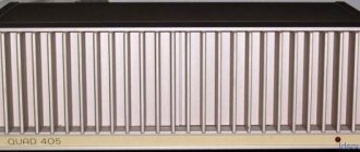
In the 70s of the last century, the English company QUAD (Quality Unit Amplifier Domestic) released a power amplifier called QUAD 405, which subsequently gained great popularity and even today many radio amateurs collect various modifications and clones of this amplifier. And the rare copies of the original amplifier themselves remain in demand on the secondary market.
It can be said that the QUAD 405 amplifier is truly legendary.
A special feature of this amplifier is that its output transistor stage operates in economical class B. In this case, distortions characteristic of this class are solved by introducing direct coupling. It was this decision that received great publicity, including in the Russian-language press (you can read many articles on this website).
Some experts note the very good sound of this amplifier with this solution.
Your own style
I would like to say a few words about the design. At the beginning, I mentioned that I like the company's informal approach to the design of its devices. However, this does not mean that I am delighted with the design of the Artera series as such. The design, unusual and original, is aimed more at fans of the brand. In any case, this appearance seems to me to be nothing more than a modernized version of the classic Quad design. Having replaced the rounded edges with strict rectangular shapes, Artera retained the rounded buttons and radiators with recognizable brutal fins and the signature gray color scheme.
Remember the glass that was on top? And this is what is underneath
A special feature of the series is the overhead glass lid, which fits into a niche in the upper part of the case and even has its own aluminum legs. Why such difficulties? In addition to purely aesthetic advantages, this also stabilizes the temperature of the device.
Technical characteristics of the first version of the amplifier QUAD 405 chassis M12368 ISS 9 and 10
The amplifier is designed to operate with a load of 4-16 Ohms
Power and distortion on a resistive load 8 Ohm: 100 Hz, up to 100 W 1000 Hz, up to 100 W 10000 Hz, up to 100 W
Output internal resistance and offset: 3.3 µH in series with 0.03 ohms; Bias
Low Frequency - 1 dB at 20 Hz High Frequency - 0.5 dB 20 kHz - 3 dB 50 kHz
These characteristics are typical for the original amplifier at the beginning of production, which uses components that are outdated today. Some modifications and well-executed clones on a modern base exceed these characteristics.
For those interested, in our time, there are several options:
1.
Try to buy an original QUAD 405 product on the secondary market; most likely, it will require further restoration repairs and/or modifications, which will be provided with information on this website.
2.
Buy a ready-made clone in China on one of the online sites. As a rule, they differ in their quality and may require upgrading by a professional specialist.
3.
For radio amateurs who want to assemble the QUAD 405 amplifier with their own hands and try out its various modifications, you can purchase DYI kits in China or order/make them yourself using a wealth of information about this amplifier, which is also added to this site.
It is expected that the information on this site will be useful both to specialists performing repairs, including restoration of original products, and to radio amateurs who want to understand the principles of operation of direct communication in an amplifier with various modifications and test the acquired knowledge in practice.
This site does not conduct any commercial activities for the sale of amplifiers and their modifications. And it is a place for radio amateurs to discuss the QUAD 405 amplifier and the unique solutions used in it and its possible improvements.
Note The site administration is not responsible for the possible consequences of self-repair or manufacture of this amplifier. All information on this website is provided for informational purposes only and assumes that you have the necessary knowledge and skill to use it.
conclusions
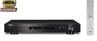
Quad Artera Solus is a universal all-in-one device, which pleased us with its extremely serious approach to the quality of work of each component and good sound. The lack of a built-in network player is partly compensated by the presence of Bluetooth and high-quality USB DAC with the ability to remotely control a playlist from the device’s remote control.
For its intended use as a compact system, this is an excellent option with virtually no competitors. A good set of inputs and outputs allows for successful system upgrades in different directions.
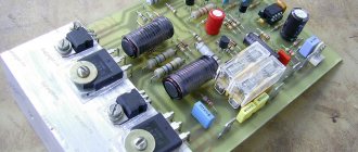
↑ AC protection
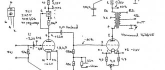
Next we move on to AC protection. I applied Alexander Kotov's defense scheme. It is quite simple and reliable, although it has a drawback: different sensitivity of operation from positive and negative input voltage. With R1 and R2 equal to 33k, the circuit operates from approximately +1.5V and -2.5V. C1 and C2 are non-polar electrolytic capacitors. I have a 2A diode bridge in a housing similar to DIP. I bought separate relays for each channel with a contact current of 10A manufactured by OMRON with 12V coils and connected them in series.
The circuit is powered by a separate transformer with a 20V secondary. It is also recommended to connect the minus or plus power supply of the circuit to the normally open contact of the power-on button (relay) on the amplifier, so that when the power is turned off with the button, the protection is immediately turned off, and does not wait until the capacitors are discharged. The delay time interval is set by capacitor C3. With a capacitance of 100 uF, the delay is about six seconds, which suits me quite well.
Related materials
ANNOUNCEMENT! QUAD boards are in stock... Dear Datagorians and guests of our cyber city! Today on dog sleds through snow and ice... Input buffer and volume control for UMZCH. Part 1... In audio frequency power amplifiers (UMPA), made according to an inverting amplifier circuit... Sprint layout macros... I want to share all my macros for Sprint Layout 5.0. They are quite enough for me, even... Toshiba is good! The newest catalog 4Q2012... I bring to the attention of fellow citizens the newest catalog of Toshiba Bipolar Power Transistors - 4th quarter 2012... Addition to the remake of the amplifier by V. Korol. Single-board wiring, separated OOS circuits... Link to the original article: UMZCH with nonlinearity compensation, 160 W (Remake of V. Korol)... Hardware has arrived for QUAD! Hooray? Hurray!... Dear Datagorians and guests of our cyber city! A heroic epic to obtain hardware for our... 160 W UMZCH with nonlinearity compensation. Modified amplifier by V. Korol... Photo of the assembly by comrade andrey This development is almost 20 years old. But she hasn’t lost hers at all... Precision low-frequency amplifiers. Danilov A. A…. Danilov A. A. Precision low frequency amplifiers. - M.: Hotline - Telecom, 2004. - 352 s,... Amateur Radio High-End. 40 best designs of lamp UMZCH for 40 years.... Amateur Radio High-End. 40 best designs of lamp UMZCH for 40 years. Small encyclopedia... A simple signal level indicator on the LM324 op-amp (8 LEDs per channel)... I don’t like it when the front panel of the amplifier is empty, it only has a volume knob and a power switch. On... Audio frequency generator on LM324. Device and toy... This is a simple pulse generator for testing or training purposes. The circuit uses a cheap and... Symmetrical ULF from available parts based on V. Korol... I would like to offer novice lovers of high-quality sound reproduction one of the developed and...
↑ First start-up and setup
We ALWAYS make the first switch-on with a 100-150 W 220V incandescent lamp connected to the break in one of the power wires of the primary transformer. My power supply has successfully started, now we connect it to the first ULF channel being tested. We don't remove the light bulb. We short-circuit the ULF input. We connect the tester to the output and measure the constant voltage at the output. In my case it turned out to be +35V, in the second channel it’s the same. Here I was upset
I started comparing it with the map of the location of the elements - everything is in order.
I found the original QUAD 405-2 circuit and began searching for the error. And I found it! It was hidden in the tangled legs of TR2 2N5551. I looked at the photo of the Chinese board, it is also soldered there according to the wiring diagram. Strange... maybe the Chinese thereby protected themselves from board cloning?! Well, oh well, I changed the base with the collector of the transistor, applied power and saw 40 mV on the tester screen, which is a good result. I don’t have an oscilloscope at home, so I boldly connected the 5-GDSH-4 test speaker and sent a signal to the input. The sound is gone, the corner is heating up normally. After listening to one channel, I burst into a happy smile, and when I switched to channel 2, everything was fine there too. A correctly assembled amplifier from working parts with the required supply voltage from +/-40V to +/-50V does not require adjustment and tuning.
↑ I cloned a Chinese clone. Chinese, cry!
The last option was the Chinese kit I saw on E-bey “ QUAD 405-2
"
The price, and even including delivery, for the salary of a simple electrician, seemed a bit high to me. I decided to go a different route! You need to find a photo of the board from the track side. Having searched on the same eBay, I found it. By the way, this board is still slightly different from the original one: Photo of the original QUAD The output stage (VC) uses transistors from Sanyo 2SD1047
in the TO-3RV package, in the build-up they cost
TIP42 °C
(although it is more desirable use
BD242
from Philips);
There is no jumper in the middle of the board; it is routed along the board's contour. Thus, the Chinese made our work easier, because while making my first version of the Hungarian version of QUAD 405
, I had a lot of trouble finding a corner and making an adapter for a radiator from it. Here everything turned out much simpler: as soon as I went to the hardware market, on the second tray I An aluminum corner 40×30×4 mm, 20 cm long (for 2 radiators you need 184 mm) caught my eye. I immediately bought it inexpensively. So let's get back to the board. A photo of the board was found. A fragment was excluded. Our magazine exists on donations from readers. The full version of this article is available only to patrons and full members of the community. Read the terms of access! and edited because the board was photographed at an angle. Then the photo was set as a template in the Sprint Layout 5.0 program, the dimensions of the board were set and the outline began. The board was repeated exactly. Translated by LUT onto prepared textolite and etched. It is pleasant to note that all the parts (see the specification in the files) are available and inexpensive. I managed to quickly buy everything from local sellers in my city. Arriving home, I began to solder everything, first bending the legs of the resistors on a homemade wooden frame. For each channel I selected low-power transistors on the tester. After soldering all components except the transistors on the heatsink, you need to prepare the adapter corner.
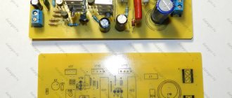
↑ QUAD cooling system
I did it this way: I cut the corner into two pieces 92 mm long, then attached them to the board and marked 2 holes in the corners of the board, drilled and screwed the corners to the boards. Next, we bend the leads of the transistors, insert them into the seats and mark the holes for the fasteners. I did this with 4 transistors on the board. Next, I drilled the corner and cut the thread. Since my corner was previously painted with something green, I sanded it on a flat surface and at the same time created an exact plane for fastening on both sides.
Then we begin to put this whole thing together: we smear the mica gasket on one side with thermal paste and apply it to the radiator with the smeared side, we smear the heat sink of the transistor and install it in the holes provided for it in the board, screw it through a flat washer to the radiator in the case of
2SD1047
.
When installing TIP42 °C
, everything is the same, only you first need to buy 4 plastic dielectric washers for TO-220 cases. The corners carrying the VK transistors are screwed through thermal paste onto a larger radiator. Mine is not very big, but quite massive. When operating at medium power, this radiator heats up to ~60 degrees.