Speakers with a diameter of 10 inches are considered the most convenient for small sound systems. This size allows you to place the subwoofer in the luggage compartment of any car. Speakers 25 centimeters are installed in a box of any design.
The box for 10-inch subwoofers can be either hermetically sealed or bass reflex. The simplest design to manufacture is the closed type. For a 25 cm speaker, the average volume of the box should be 15 liters. It is not worth doing less than 10 liters, as the low frequencies will be too “hard” and the bass will not be rich. If the internal volume of the box exceeds 20 liters, the sound will lose clarity.
Subwoofer box 10
A closed box for a 10-inch subwoofer with your own hands can be easily made from multi-layer plywood or MDF. The simplest design is made from rectangular parts. In some models, the front and rear walls are installed at an angle, and the finished structure has a trapezoid shape. A closed box for a 10-inch subwoofer must be completely sealed, so after assembling the speaker, all internal seams are coated with silicone sealant. The closed-type design does not require adjustment, while more complex systems with bass reflexes have to be adjusted.
Subwoofer housing drawings
The tunnel has a correspondingly large cross-section. Thanks to this we get two things:
- greater acoustic resistance of the tunnel, that is, greater efficiency;
- lower air speed in the tunnel itself - a strong loudspeaker can be used without “sticking” to the tunnel.
At the exit of the bass reflex and speaker there is an additional chamber/tunnel with a much larger cross-section, which increases the efficiency of the subwoofer as a whole.
Subwoofer box drawings 10
Before calculating the speakers for the subwoofer, you need to select a loudspeaker. Among various speakers with a diameter of 10”, the Herz DS250 speaker shows good results in reproducing low frequencies, so the drawing of the box for a 10” subwoofer is designed for this model.
The dynamic low-frequency head has the following parameters:
- Rated power – 200 watts
- Peak power – 400 watts
- Sensitivity – 90 dB
- Coil resistance – 4 ohms
The design of the loudspeaker uses a dense cone-shaped diffuser made of polypropylene, into which mineral additives are introduced for rigidity. The butyl rubber suspension provides high wear resistance in any climatic conditions during operation. Thanks to enhanced ventilation, the heat-resistant voice coil is protected from overheating at high power. The calculation of the box for subwoofer 10 is based on the diameter of the loudspeaker used. The material for the closed box is multi-layer plywood or pressed MDF fiber fraction. These materials are easy to process, so cutting and assembling a closed column can be done at home.
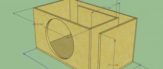
How to calculate a box for a 10-inch subwoofer
The housing parts for a 25 cm subwoofer must have a thickness of at least 18 mm, since smaller values cause resonating overtones that negatively affect the sound picture. The box for a 10-inch subwoofer is made in the form of a trapezoid, the front wall of which has an inclination angle of 35-400. All structural parts are connected using self-tapping screws. After assembling the device, all internal seams must be treated with sealing paste. Silicone sealant is used for this. The terminal block for connecting wires is also sealed.
The construction uses MDF material with a thickness of 20 mm. A closed-type box, unlike a bass-reflex box, is not adjustable, so you can change the quality of low-frequency reproduction by filling the internal volume of the box with synthetic padding. It is recommended to try both an empty acoustic resonator and one with filler and choose the best option.
Cutting parts
So, you have decided on the shape for the sub box and you have a drawing.
Mark the sheet according to the parts and cut according to the marked dimensions. Use a disk with a large number of teeth; the smaller the tooth size of a circular saw blade, the fewer chips you will get, and their size will be insignificant.
If you use a manual circular saw and your hand is not full, it is better to use a guide so as not to accidentally “fill up” the cut.
It is better to do this work together, since it is quite inconvenient for one person to turn large sheets and hold them while working.
Below is a good video from Rockford Fosgate, albeit in English, but everything is clear here without translation - choosing the shape of the body, lining up the parts, cutting.
10" subwoofer box
The enclosed box for a 10-inch subwoofer is easy to manufacture and assemble, has good acoustic characteristics, and produces clear bass with good articulation. The disadvantage of the design is low efficiency. A subwoofer speaker with a bass reflex reproduces low frequencies much more efficiently and the device can be tuned, highlighting part of the low-frequency range. In this section, the amplitude-frequency response will rise. The bass reflex is larger than a closed box and requires more complex calculations. A characteristic disadvantage of bass reflex designs is the following. Powerful bass loses its punch and clarity and becomes more diffuse.
Bass reflexes for subwoofers come in slot and tubular types. The first type of bass reflex is more difficult to manufacture and configure, therefore, for home-made designs, a tubular bass reflex is preferable. You can buy two coaxial pipe sections or make it yourself. Setting up such a system is carried out by moving the internal segment of the cylinder, from which the length of the bass reflex can increase or decrease. To get powerful bass, you can make a box for two 10-inch subwoofers. It is recommended to install two speakers with double the volume. In this case, the bass reproduction effect will be similar to that of a larger diameter speaker. The sound will be deep and smooth.
The box for two 10 subwoofers comes in different structural types. The loudspeakers are located in a common box, which is equipped with two tubular bass reflexes. This system allows you to configure optimal reproduction of low frequencies. Some designs have speaker cones facing each other, or one speaker placed behind the other. Measuring microphones and special computer programs are used to fine-tune complex subwoofers.
Project “48 liters” or assembling a subwoofer for music from an S-90 speaker cabinet.
The process of assembling a subwoofer in a “closed box” acoustic design. Measurements, graphs, diagrams. Designed for a prepared reader. 1.
As usual, it all starts with bait. This time the bait was the author's article An excellent subwoofer for music and cinema. Graphs showing the achieved results:
The results are very good!
“A closed box (abbreviated ZY
) is the simplest acoustic design, but far from primitive; on the contrary, it has a number of advantages over others. What happens to the speaker's performance when installed in a closed box? It depends on one single quantity - the volume of the box. If the volume is so large that the speaker practically does not notice it, we come to the infinite screen option. In practice, this situation is achieved when the volume of the box (or other closed volume located behind the diffuser, or, more simply put, what is hidden there - the trunk of a car) exceeds the equivalent volume of the speaker by three times or more. If this relationship is satisfied, the resonant frequency and overall quality factor of the system will remain almost the same as they were for the speaker. This means that they must be chosen accordingly. It is known that the acoustic system will have the smoothest frequency response with a total quality factor of 0.7. At lower values, the impulse characteristics improve, but the frequency decay begins quite high in frequency. At large values, the frequency response becomes higher near resonance, and the transient characteristics deteriorate somewhat. If you are focusing on classical music, jazz or acoustic genres, the optimal choice would be a slightly overdamped system with a quality factor of 0.5 - 0.7. For more energetic genres, emphasizing the lows, which is achieved with a quality factor of 0.8 - 0.9, will not hurt. And finally, rap fans will have a blast if the system has a quality factor of 1.0 or even higher. The value of 1.2 should, perhaps, be recognized as the limit for any genre that claims to be musical. » ©
Source: DIY acoustic systems Gaponenko S.V. 2013
2.
To better understand graphs, it is recommended that you become familiar with the concept of Group Delay Time (GDT).
3.
It would seem that there is a Magnat 530A sub in the house - an ordinary sub with a bass reflex (FI).
What else is missing?
After recently listening to different amplifiers, the opinion was voiced that “the bottom is smeared.” Which, to be honest, was not news to me.
The archives preserved measurements of the 530th. A measuring mic for high sound pressures was used:
Mick - MK102:
Combined graphs:
Okay, let Kg=1.75% at 40 Hz. Tolerable.
I had to torture the sub with 40Hz 100ms bursts to see the transient processes of the sub. This is what the message at the sound card output looks like (picture from an oscilloscope):
And this is how the sound card sees the same signal in recording mode from the linear input:
The train of thought was this: we need to mute the sub’s FI in order to understand whether it is possible to use it in this form.
The subwoofer's FIs were muffled with rag rollers, and a 40Hz 100ms tone burst was applied to the subwoofer's input. The recording from the microphone was “a little” surprising:
The result was not four, as in the original signal, but five (!) signal periods. Plus an oscillatory process at a frequency of 71 Hz (circled in red) due to damped FI. Hmmm, things are really bad. (
Frequency response of a subwoofer with muted FI (red) and open FI (blue):
Conclusions about the Magnat 530A subwoofer: - the frequency response of the subwoofer is bad, even with open FI, even with closed FI - GVZ is even worse in both versions - THD is tolerable, but this does not save the situation - the subwoofer is only suitable for special effects in movies
4.
Speaker for experiments. Where to get? For some reason I didn’t want to disassemble the sub in order to get the speaker for experiments.
In the house there was a free gift “sub” from AC Electronics 25AC-132
with a half-dead speaker 35GDN-1S-4 The leads fell apart either from time or from use. I had to spend an evening replacing them.
To measure the TS (Thiel-Small) parameters, the JBL Speakershop program was used. The FI hole had to be plugged with a plastic cup (see photo above). That day I was haunted by a rake of failure: - the generator, assembled 20+ years ago, was producing RF interference, which greatly interfered with the measurements - the DSO-2150 USB oscilloscope, as luck would have it, began to pick up interference (I had to measure RMS with a multimeter) - the contact is in the connector (on the back panel of the test box) suddenly added a resistance of 10-70 Ohms, which magically changed, because of which JBL Speakershop began to issue strange messages (like “Boy! What are you even measuring there?”) This nasty thing:
Only by late evening the path with the rake ended, and on the 9th attempt (I’m not lying) it was possible to obtain reliable characteristics of the 35GDN-1S-4 speaker:
And so, there is a speaker. Where can I get the case?
5.
A gift to your loved one for the New Year. For a symbolic 200 UAH. ($7) was purchased... the body of everyone's favorite S-90B speaker:
The bonus was a filter board
After shaking out everything unnecessary from the hull, the total internal volume of the S-90B hull was 48 liters
. I use real speaker data, a rough calculation of the ZY was made:
48 liters are ideal for obtaining a quality factor of 0.7. Checking the calculation in JBL Speakershop:
For a quality factor of 0.7, the program suggested a volume of 31.3 liters. And for 48 liters the quality factor was 0.64, which is very good for a musical subwoofer.
To transform the S-90B case into a ZYA, a front panel was ordered from a furniture maker friend according to the sketch:
And on December 27, 2020 everything was ready:
The panel was secured with six self-tapping screws (so far without the use of glue or other adhesive compounds). A cotton swab didn't seem enough to me:
And I wanted to stuff a soft toy inside:
The wife, seeing all this, twirled her finger at her temple. I had to feel sorry for the beast.
Screwed the speaker:
I dragged the sub to the measurement laboratory:
Measurement conditions: - there are no filters/correction - test signals are supplied from the output of the sound card through the PA directly to the frequency response speaker (measurement with pink noise; graph in yellow):
Graphs in red and blue - frequency response of the Magnat subwoofer.
What I didn’t expect to see was a flat frequency response almost up to 8-10 kHz. And according to the passport it’s only 5 kHz:
Response to tone burst 40Hz 100ms:
Four periods are still turning... turning... into 4-5 periods. Mystic! ©
The good news is that there is no significant oscillatory process at the end of the sending (the quality factor is about 0.7). Reducing the quality factor of the system by filling the housing with a sound absorber is unlikely to improve the situation.
If you believe the primary sources, with a quality factor of 0.5, the oscillatory process is completely absent. What volume of cell is required for a quality factor of at least 0.55?
315 liters! That's enough for today.
28.12.2020 6.
Amplifier for subwoofer. At the experimental stage, the use of a separate PA is acceptable. But in the future?
Among the useless purchases in the house, there was a ready-made PA board based on the TPA3116 chip. Having quickly read the documentation, I did not find the numbers at what point clipping begins.
The board is powered by a 12V battery (so that there is no zero connection with the oscilloscope). A 1 kHz test signal was supplied from an mp3 player. The maximum that we were able to squeeze out of the microcircuit without clipping into a 4 Ohm load was only 7.4V RMS:
With a 24V power supply (two 12V batteries, the load is also 4 Ohms) only 12.4V RMS.
The heatsink on the chip began to noticeably heat up!
Honest numbers for TPA3116 (4 Ohm load): - 12 W with 12V power supply - 36 W with 24V power supply
And let 60W be left for advertising. ))
The rated power of the 35GDN-1S-4 is only 35W, the amplifier power on the tpa3116 is sufficient. Of course, I would like to have an amplifier with a reserve, but...
7.
Linkwitz transformer. For the ground cell, it would be logical to use a specialized frequency response corrector (the so-called Linkwitz transformer). Calculation:
Let's see what the simulation shows:
An additional “bonus” is a time delay of 3.2 ms. (Thus, in order to coordinate the sub with the rest of the acoustics, you need to have a “head start” of 3.2 ms, or move the sub forward by 330 m/s * 3.2 ms = 1.06 m.
You can cheat: invert the signal phase by 180 degrees at the subwoofer input, thus obtaining pseudo-advanced, and move the sub “to the rear” (by the way, this method works; tested).
8.
Proportional integrating filter (PI filter) as a replacement for the Linkwitz transformer. A PI filter is just two resistors and one capacitor. Time delay 2.4 ms (equivalent to 0.8 meters):
As for me, it is easier to solder three passive elements than an operational amplifier circuit with a +-15V power supply. ))
The result is a section with a rise in frequency response from 125 Hz
up to 37 Hz
6 dB rise.
It is possible to try to squeeze out a greater rise (10 dB or more), but - you will need a higher power amplifier (tpa3116 and so on at the limit) - the speaker will operate in peak overload mode - as a result, the harmonic coefficient will be several times higher
9.
On the path to further simplification. R1 is removed from the PI filter circuit, i.e. the simplest low-pass filter is obtained. At the same values, the -3dB point has moved to 44 Hz:
*You can always adjust the value by changing R2 or C1. Latency 2.8ms:
Result: the Linkwitz transformer and low-pass filter for the subwoofer are replaced by a passive RC circuit.
10.
Listening to the subwoofer. I was no longer in the mood to experiment with the amplifier on the tpa3116, so the subwoofer was connected to one channel of a 100W amplifier (which has a damping factor of about 100):
Subwoofer connection diagram
The circuit on the wires is a low-pass filter and a corrector from point 9. Total frequency response (Heco speaker + subwoofer) at the listening point:
That rare case when the graph shows one thing (low frequencies, as it were, a little), but in reality there is more than enough low end.
The number of listeners is only two. The opinion was unanimous: the sub adds very well. Exactly what Heco speakers lacked. There is no smudged bottom or muttering. We listened to musical compositions by various artists and authors: - Youngblood Brass Band - KITARO - YELLO - Leonard Cohen - Pink Martini - Richard Clayderman (“Tango”) - Tommy Emmanuel and others.
The musical sub was a success! For the first time I listened normally to ZYa playing with a quality factor of about 0.7. After that I don't want to listen to FI sub anymore.
Finally, I measured how much power was supplied to the woofer. Oscilloscope in memory mode, trigger threshold 7.5V:
Peaks with an amplitude of 10V passed when the volume control was -3 dB. For comfortable listening (together with neighbors) -9..-6 dB is enough. So tpa3116 should cope (to whom should it? fz). If only it didn’t work out with it, like with the TDA7294 in the experiment 20 years ago. ))
That's all. Happy experiments everyone.
Update from 02.21.2021 Bass reflex from the S-90B speaker:
FI parameters: - internal volume 1.0 l - area 37.4 sq. cm - equivalent length 26.7 cm