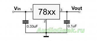
The bipolar power supply is built on adjustable linear stabilizers LM317 and LM337, which are capable of delivering current up to 1.5A, adjusting the output voltage in the range of ±1.25-37V and have protection against short-circuit, overload, and over-temperature. Thus, the adjustable power supply on LM317+LM337 can be used to power various electronic equipment with a stabilized bipolar voltage, with the ability to set the required value.
I made this power supply for the convenience of checking low-power UMZCH.
Main technical characteristics
Input voltage (AC), V ..... no more than 25-0-25
Maximum output current, A….. 2.2
Rated output current, A….. 1.5
Output voltage (DC), V….. adjustable from ±1.25 to ±30
Note. Rated and maximum currents are indicated for a difference of up to 15V between the input and output voltage of the stabilizer. If this difference is greater, then the maximum and rated currents will decrease in accordance with the graph below.
It is also important to know that according to the technical descriptions for LM317 and LM337, in order to obtain the required current, the power dissipation on the stabilizer should not exceed 20 W, otherwise the overload protection will be triggered and the output power will be limited.
LM 317 and LM 337 pin locations
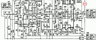
Scheme of a bipolar regulated power supply for LM 317+ LM 337
The AC voltage from the secondary winding of the transformer is supplied to the noise suppression capacitor C1, and then to the diode bridge VDS1, where it is rectified and supplied to the linear stabilizers LM317 and LM337. The LM317 adjustable stabilizer stabilizes the positive arm, and the LM337 adjustable stabilizer stabilizes the negative arm.
Voltage regulation is carried out by trimming resistors R5 and R6. The required value can be calculated using the formula (for a positive leverage):
Types of power supplies
All power sources can be divided into two large classes:
- pulse;
- transformer
These terms are not very precise - a transformer power supply can have both a linear and a switching voltage stabilizer, and a switching power supply contains a transformer.
Each type has its own advantages and disadvantages based on the principle of operation. A transformer power supply with a linear voltage regulator distributes energy between the load and the regulating element (usually a power transistor) and is a voltage divider. One arm is the control element, the other is the load.
We recommend: Types of power supplies and their purpose
When the voltage across the load decreases (for example, due to an increase in current consumption), the transistor opens slightly and maintains this voltage constant. When the voltage across the load increases, the process is reversed - the transistor closes. This is how the stabilization process occurs.
Operating principle of a linear stabilizer.
Disadvantages of this scheme:
- it is required that the input voltage be noticeably higher than the output voltage;
- a current equal to the load current constantly flows through the regulating transistor - a lot of power is wasted;
- The efficiency, even theoretically, cannot exceed the ratio Uout/Uin.
The advantages are:
- relatively simple and inexpensive scheme;
- the output voltage is free from high-frequency parasitic components (power supply interference is minimal).
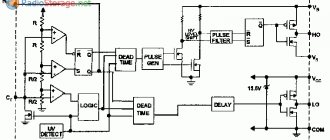
A switching power supply operates on a different principle. Here the energy is distributed over time. Key transistors have only two states - they are either completely open or completely closed. The duration of the open position determines the average current through the primary winding of the transformer and the average voltage on the output capacitors of the filter (and, accordingly, on the load). It is convenient to control this process using the pulse width modulation (PWM) method, when the conversion frequency remains constant and only the pulse length changes.
In an ideal pulsed source of stabilized voltage, the switches in the open position have zero resistance, there is no voltage drop, and in the closed position there is no current at all. Therefore, energy is not dissipated in transistors. In practice, not everything is so rosy. There are no ideal transistors, so in the open state a certain voltage drops across them (resistance is not zero), and in the closed state there is a leakage current (resistance is not infinity).
But the main losses that reduce efficiency occur for another reason. Transistor switches do not switch from one state to the opposite instantly. This takes time, depending on the speed of the element. During the transition, a through current flows through the transistor, the voltage across it drops - therefore, power is released. These losses are called switching losses, their magnitude depends on the conversion frequency.
Real and ideal switch in switching power supply.
But still, the efficiency of such a source is higher than that of a linear one. And this is the main advantage of such a scheme. Another advantage is the smaller size and weight of the power source. This is achieved due to the fact that the conversion is carried out at a fairly high frequency - up to several tens of kilohertz. Therefore, the heaviest and most bulky element (power transformer) turns out to be light and compact. The main disadvantage is the complexity of the scheme.
Typically, linear voltage sources are used for currents up to 2 A. Closer to currents of 3 A and higher, the advantages of pulse generators begin to outweigh.
Result:
The stabilizer is fully operational and can be used as a voltage stabilizer (subject to the presence of a load) and a current stabilizer.
There are also many different application schemes for increasing the output power, using it as a charger for batteries, etc. The cost of the subject is quite reasonable, considering that offline I can buy one for at least 30 rubles, and in a well-known Russian online store for 19 rubles, which is significantly more expensive than the one being reviewed. With that, let me take my leave, good luck!
The product was provided for writing a review by the store. The review was published in accordance with clause 18 of the Site Rules.
Main components of a regulated power supply
The transformer power supply in most cases is made according to the following block diagram.
Transformer power supply units.
A step-down transformer reduces the network voltage to the required level. The resulting alternating voltage is converted into pulsed voltage using a rectifier. The choice of its circuit depends on the circuit of the secondary windings of the transformer. The most commonly used full-wave bridge circuit is used. Less often - half-wave, since it does not allow the transformer’s power to be fully used, and the ripple level is higher. If the secondary winding has a center point brought out, then the full-wave circuit can be built with two diodes instead of four.
Full-wave rectifier for midpoint transformer.
If the transformer is three-phase (and there is a three-phase circuit to power the primary winding), then the rectifier can be assembled using a three-phase circuit. In this case, the ripple level is the lowest, and the power of the transformer is used most fully.
After the rectifier, a filter is installed that smoothes the pulse voltage to constant. Typically, the filter consists of an oxide capacitor, parallel to which a low-capacity ceramic capacitor is placed. Its purpose is to compensate for the structural inductance of the oxide capacitor, which is made in the form of a rolled strip of foil. As a result, the resulting parasitic inductance of such a coil worsens the filtering properties at high frequencies.
Next is the stabilizer. It can be either linear or pulsed. The pulse type is more complicated and negates all the advantages of a transformer power supply in the output current niche of up to 2..3 amperes. If you need an output current higher than this value, it is easier to switch the entire power supply, so a linear regulator is usually used here.
The output filter is based on an oxide capacitor with a relatively small capacitance.
Generalized block diagram of a pulse power supply.
Switching power supplies are built on a different principle. Since the current consumed is sharply non-sinusoidal, a filter is installed at the input. It does not affect the performance of the unit in any way, which is why many industrial manufacturers of Economy class power supplies do not install it. You don’t have to install it in a simple homemade source, but this will lead to the fact that devices on microcontrollers powered by the same 220 volt network will begin to fail or work unpredictably.
Then the mains voltage is straightened and smoothed out. An inverter using transistor switches in the primary winding circuit of the transformer creates pulses with an amplitude of 220 volts and a high frequency - up to several tens of kilohertz, in contrast to 50 hertz in the network. Due to this, the power transformer is compact and lightweight. The secondary winding voltage is rectified and filtered. Due to the high conversion frequency, smaller capacitors can be used here, which has a positive effect on the dimensions of the device. Also, in high-frequency voltage filters, it becomes advisable to use chokes - small-sized inductors effectively smooth out HF pulsations.
Voltage regulation and current limitation are performed through feedback circuits, which are supplied with voltage from the source output. If, due to an increase in load, the voltage begins to decrease, then the control circuit increases the interval of the open state of the keys without reducing the frequency (pulse width control method). If the voltage needs to be reduced (including to limit the output current), the time the switches are open is reduced.
Characteristics of LM317t
Here are the main parameters of the LM317 stabilizer:
- Input voltage, max: 40 V.
- Output voltage, min: 1.25 V.
- Reference voltage (Vref): 0.1 to 1.3 V.
- Load current, max: 1.5 A.
- Output voltage instability: 0.1%.
- Current Adj: 50…100 mA.
- Housing: TO-220, TO-92, TO-3, D2PAK.
For detailed parameters, see the datasheet in Russian, which can be downloaded at the end of the article.
How to select components
For a transformer source, first of all, a transformer is selected. In most cases, it is taken ready-made from what is available. This node must produce the required current at maximum voltage. The combination of these parameters is ensured by the overall power of the transformer. For industrial devices, parameters can be found in the reference book. For random transformers, the power can be determined by the core dimensions (in centimeters).
Core area for different types of transformers.
Power is calculated using the formula:
P=S2/1.44 where:
- P-power in Watts;
- S is the cross section in square centimeters.
For practical purposes, the power must also be multiplied by the efficiency. For example, a transformer with a core area of 6 sq.cm. at a voltage of 35 volts and a stabilizer output voltage of 30 volts (the overall efficiency can be taken as 0.75) it is capable of delivering power P=(36/1.44)*0.75=18.75 watts. The maximum current will be I=P/U=18.75/35=0.5 A.
If the transformer passes power, but the secondary winding is designed for a different voltage, it can be removed and a new one wound (if it fits). The number of turns is calculated as follows:
- the number of turns per volt is determined by the formula 50/S, where S is the core area in sq.cm;
- this value is multiplied by the required voltage level.
So, for an area of 6 cm per 1 volt there are 50/6 = 8.3 turns per volt. For a voltage of 35 volts, the winding must have 35 * 8.3 = 291 turns. The wire diameter is calculated using the formula D=0.02, where I is the current in milliamps. For a current of 5 amperes, you need to take a wire with a diameter of 0.02 * = 70 * 0.02 = 1.4 mm.
If a high-power transistor is selected for a linear regulator, the main criterion for application is the collector current. It must cover the load current with a margin. This parameter for common domestic and foreign transistors is given in the table.
| Transistor | Maximum collector current (constant), A |
| KT818 (819) | 10 |
| KT825 (827) | 20 |
| KT805 | 5 |
| TIP36 | 25 |
| 2N3055 | 15 |
| MJE13009 | 12 |
When operating in modes close to the maximum current, transistors must be installed on radiators.
You also need to pay attention to such a parameter as the maximum voltage between the collector and emitter. With an input voltage of 35 volts and an output voltage of 1.5, the difference will be 33.5 volts; for some semiconductor devices this is unacceptable.
The capacity of the oxide capacitor located after the rectifier is selected based on the load. There are formulas for calculating filter parameters, but in practice the approach is simple: the more, the better. There are two restrictions imposed on the capacity:
- capacitor dimensions;
- inrush current per charge, which can be significant with a large capacity.
The output capacitor of the power supply can have a capacity of about 1000 µF.
Foreign and Russian analogues
What can replace lm317? Complete analogues of the microcircuit are GL317, SG317, UPC317, ECG1900. A very well-known domestic analogue of lm317t with a fixed voltage is the KP142EN12 microcircuit. If you need an adjustable linear stabilizer, then KREN12A is suitable (B is also possible).
Operational safety
The maximum voltage between input and output should not exceed 40 V. Dissipation power should not exceed 20 W. The soldering temperature should not exceed 260 °C, while maintaining a distance from the microcircuit body of more than 1.6 mm and a heating time of up to 10 seconds. The storage temperature of the device should be in the range from -65 to + 150 °C, operating temperature no more than + 150 °C.
These are maximum values that can damage the device or affect its stability. The microcircuit is well protected from thermal overload and contact short circuit. However, you should not exceed the permissible parameters during operation in order to avoid its failure and achieve maximum reliable operation.
Laboratory power supply circuits
On the Internet you can find many diagrams of laboratory power supplies. The choice is determined based on the tasks, the qualifications of the technician and the availability of components.
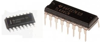
Switching power supply on tl494
The TL494 chip is iconic in the field of switching power supplies. Most power supplies of desktop computers are made on its basis.
Pinout and pin assignment of TL494.
Based on the TL494, you can also make a laboratory source in accordance with the structure discussed above.
Switching power supply circuit on TL494.
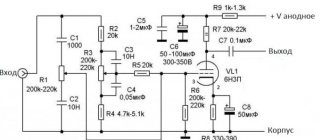
A surge filter is installed at the input of the unit. After it there is a high-voltage rectifier on VDS1 (you can use any assemblies and diodes for the appropriate voltage), which generates a constant voltage of 220 volts. An auxiliary transformer TR3 with a rectifier VDS2 is connected in parallel to the rectifier. These elements generate +12 volts to power the microcircuits. TL494 generates a sequence of pulses, the frequency of which is determined by the C3R3 chain. The signal is amplified by switches on transistors T1, T2 and through transformer TR1 is supplied to bases T3, T4. These powerful transistors form high-voltage pulses in the primary winding of transformer TR2. Pulses with a repetition rate of several tens of kilohertz are transformed into the secondary winding of the transformer, rectified by the D5 assembly, filtered and supplied to the consumer.
The voltage feedback circuit is formed on elements OP3, OP4 of the operational amplifier. Resistor R15 sets the required output level. The actual current is measured as the voltage drop across the shunt of resistors R25, R26. Elements OP1, OP2 create a circuit for limiting the maximum current (the required value is set by a potentiometer). The TL494 microcircuit, depending on the specified current and voltage, increases or decreases the duration of the open state of the keys. Transistors T3, T4, as well as diode D5 must be installed on radiators. It is highly desirable to organize forced airflow of circuit elements. The fan can be connected to a DC voltage source of +12 volts.
The ratings and types of elements are shown in the diagram. Many components, including winding elements, can be taken from a faulty or unnecessary computer power supply. Choke L5 is wound on a yellow toroidal core and contains 50 turns of wire with a diameter of 1.5 mm.
Power supply with switching stabilizer.
Another option for using the TL494 chip is in a pulse stabilizer for a power supply, made according to a “transformer” circuit. This source produces voltage from 0 to 30 volts at a current of up to 5 amperes.
Here the microcircuit controls the opening and closing of the key on transistor VT1. In the open state, energy is accumulated in the throttle L1, in the closed state it is transferred from the throttle to the consumer. Diode VD1 “eats” the negative voltage pulse that occurs when switching a circuit with high inductance.
The greater the load, the faster the energy in the inductance is consumed, the faster the voltage on capacitor C4 drops, the longer the transistor must be opened. The feedback voltage is supplied to the microcircuit from the potentiometer R9. They set the required output level. The current is measured as the voltage drop across shunt R12. The required current limit level is set using R3.
The circuit section containing the LM358 operational amplifier and the K155LA3 logic chip (it is better to use the K555LA3) serves to indicate the power supply mode - current stabilization or voltage stabilization.
Resistors R4 and R10, designed for precise adjustment of voltage and current, can be omitted - in practice they are of no use. During assembly, it is necessary to ensure effective cooling of the elements:
- transistor VT1;
- diode VD1;
- throttle L1;
- shunt R12.
The use of a cooler is highly recommended. Instruments should also be installed to indicate the current current and voltage values.
We recommend trying: Converting a computer power supply into a laboratory power supply with voltage regulation
On a p210 transistor
P210 transistors have been preserved in the storage rooms of many radio amateurs. It is not so easy to find applications for them - more modern components have appeared, their frequency characteristics and gain leave the outdated device far behind. But one parameter - the maximum collector current of the P210, which is 12 A when installed on a radiator - allows them to be used today in regulated power supplies.
The circuit is simple, but you need to pay attention that the transistor is connected to the negative arm (P210 has a pnp structure). The capacitor after the rectifier must have a capacity of at least 5000 μF, and at the output - at least 1000 μF. P210 can have a low gain, so transistor VT2 is added to it - any low-power pnp structure.
Power supply circuit using transistor P210 or similar.
The source can use a transformer TN-36-127/220-50, which has 4 secondary windings of 6.3 volts each. By connecting two of them in series, you can build a homemade power supply with an output voltage of up to 12 V, and if you connect 4 windings in the same way - up to 24 V. You can also use other step-down transformers that are suitable for current and voltage.
Connection diagram of TN-36-127/220-50 windings.
Similar controlled voltage sources can be built using other transistors, including npn. In this case, the power element is included in the positive arm of the power supply unit.
Power supply based on transistor KT829.
These simple power supplies do not have short circuit or overload protection. It is highly advisable to install a voltmeter and an ammeter at the output to monitor the mode. The transistor must be installed on the radiator.
On lm317
Using the LM317 chip, you can assemble a power supply with a linear voltage regulator and adjustable current limit. The main advantage of this microcircuit is its simple connection circuit with a minimum of wiring. The standard connection diagram looks like this:
Standard connection circuit LM317.
The output voltage is set by the divider R1R2. By changing the output voltage, the microcircuit tries to hold the current through the divider so that the voltage drop across R1 is 1.25 volts. Therefore, the larger R2, the greater the output voltage. If you replace R2 with a potentiometer, the output voltage can be adjusted. The output level is calculated using the formula Uout=1.25*(1+R2/R1).
If R2 = 0, then the output will be 1.25 volts - this is the minimum possible voltage for this connection.
On the Internet there are many circuits on the LM317 with voltage regulation from zero volts (including applying a negative bias to the Adjust pin). Most of these technical solutions only work on paper.
In the datasheet for the chip there is such a connection diagram.
This is enough to build a simple adjustable laboratory, but there is a problem. The microcircuit in such a connection produces no more than 1.5 A, even if it is installed on a radiator. The second disadvantage is that in order to get an output voltage of 30 V, about 35 VDC must be applied to the input. If it is necessary to obtain an output level close to the minimum, restrictions on the maximum power dissipation come into effect - with a differential of 35/1.25, the maximum current can be 0.3..0.5 A (depending on the microcircuit package). This is very little. Therefore, the microcircuit must be powered with an external transistor.
The manufacturer offers such a scheme.
As an external one, you can use a domestic transistor of the pnp structure KT818 with the letter index B-G (KT818A may not pass the collector-emitter voltage). If it is installed on a radiator, the maximum current in theory will be 10 A, but this is if there are no restrictions on the current of the rectifier diodes and the power of the transformer.
Power transistors of the NPN structure are more common. If you need to power up the stabilizer with such an element, you can use the circuit from the datasheet.
Using a powerful npn element recommended by the chip developer.
Here, a low-power pnp transistor is used (you can use the domestic KT814), which controls a powerful npn element (for example, KT819).
Often used in practice, the use of a powerful npn element.
But more often a switch is used that is not provided for by the developer - the transistor is switched on by the base to the output of the microcircuit.
Each of the proposed circuits can be used as a laboratory power supply on the LM317, but in practice the LBP circuit, supplemented by maximum current adjustment, is popular.
Power supply circuit for LM317.
The device is powered by a mains transformer with two windings. The additional winding serves to create a negative power arm of the op-amp LM301, on which the current limiting circuit is assembled. The operational amplifier is connected according to a comparator circuit - on one pin there is a reference voltage, regulated using P1, on the other - the voltage created by the actual current on the shunt resistor R5.
If the actual current exceeds the set current, the state at the output of the comparator changes to the opposite. The LED lights up and the voltage is limited to a level that maintains the set current value.
Based on this circuit, a stationary power supply is assembled, providing two voltage channels with regulation of 1.25..30 volts and current limitation within 5A for each channel.
Appearance of the power supply.
If necessary, the channels can be connected in series to a common point - a bipolar source will be obtained. 90+ percent of components and materials, including the housing, can usually be found in the storage rooms of any radio amateur.
Internal layout of the power supply.
The unit is assembled in a housing from a faulty frequency response meter “Test”. Power transformers of unknown origin were used, suitable in power and voltage (one had to rewind the secondary winding to obtain a voltage of 35 volts). There was not enough space on it for an additional winding, so the negative arm of one of the channels is powered from a separate small transformer.
Stabilizer printed circuit board.
Most of the elements are located on the boards; the drawing and location of the parts can be found on the Internet. You can design and manufacture your own board.
Recommended printed circuit board design and arrangement of elements on it.
The measurement scheme has been changed - voltmeter-ammeter blocks have been used, which can be purchased on trading platforms on the Internet. Elements R8, R9, P4 and an analog voltmeter do not need to be installed in this version. The output transistors are installed on radiators located on the rear wall of the case. The rectifier diodes are installed on homemade radiators.
The domestic analogue of LM317 is the 142EN12A microcircuit.
During setup, the power supply was loaded with car light bulbs up to a current of 5 A, and the trimming resistor P1 (at maximum resistance P2) set the protection to trigger.
The circuit proved to be efficient, although the current limiting does not work according to the best algorithm. When the current goes beyond the limits, the voltage simply drops to a minimum. It is better to find a circuit that in this case switches the power supply to current stabilization mode. If you need a higher voltage LPS (with an output level of up to 60 volts), it can be made on the LM317HV chip and use transformers with the appropriate voltage.
On lt1083
Instead of the LM317 chip, you can use the LT1083. Its specific differences:
- low voltage drop (at maximum current no more than 1.5 V);
- increased output current.
The first advantage leads to the fact that less power will be dissipated on the microcircuit, therefore, at low voltage values, increased current can be removed from it. In addition, the output voltage of the transformer can be made lower (not much, by 1..2 volts, but sometimes this is critical).
The second advantage leads to the fact that in many cases you can do without an external powerful transistor. The maximum current supplied by the LT108X series stabilizers is shown in the table.
| Chip | Maximum current, A |
| LT1083 | 3 |
| LT1084 | 5 |
| LT1085 | 7,5 |
A current of 7.5 amperes covers 90+ percent of the needs of a home laboratory. Otherwise, regarding the topic of the review, the circuit does not differ from the circuit on the LM317.
Pinout and typical connection diagram for linear stabilizers of the LT108X series.
Article on the topic: Computer power supply circuits - complete description with examples
Charger based on LM317, reinforced with a transistor with protection against short circuit and polarity reversal
On one of the workshop pages, I described a simple charger on the LM317 and I want to improve it a little. This charger must charge 3 LI-Ion batteries with a voltage of up to 12.6V, must be able to keep the current within the specified parameters, and also be able to protect charging from short circuits and polarity reversal. At first, I wanted to finish the charging a little, but there was no 1.5A LM available and I had to install the LM317LZ at 100mA, which radically changed the entire circuit.
Charger circuit based on LM317LZ, reinforced with a transistor and with protection against short circuit and polarity reversal
The main unit is assembled on an LM317LZ reinforced with a PNP transistor of the KT835 type. When a current of about 10 mA passes through R3, transistor Q1 is cut off and the main current flows through it. Resistors R5R8R10 set the voltage to 12.6V.
The transistor stage at Q4Q5 contains current limitation. When the drop on R13 reaches 0.6V, Q5 opens and Q4 opens, bypassing the LM317LZ control leg. The current can be calculated using the formula R13=0.6/Iload. By the way, the current can be absolutely any, at least 20A. It all depends on the amplifying transistor and diode bridge
The field switch Q3 has short circuit protection and polarity reversal protection, indication on LED1. By the way, I used transistors Q1-KT835 Q2-C945 Q3-IRF630 Q4-S9012 Q5-C945
I assembled the charger and it worked immediately. The only thing I didn’t think through was the charging end indication, but that’s for next time.
Photo of the assembled charger on LM317LZ
Printed circuit board of the charger on LM317, reinforced with a transistor with protection against short circuit and polarity reversal
Download the printed circuit board Archive password jhg561bvlkm556
Video of charger on LM317LZ
In order not to miss the latest updates in the workshop, subscribe to updates on VKontakte or Odnoklassniki, you can also subscribe to updates by email in the column on the right
Don’t want to delve into the routine of radio electronics? I recommend paying attention to the proposals of our Chinese friends. For a very reasonable price you can purchase quite high-quality chargers
Charger 12V 1.3A
A simple charger with an LED charging indicator, green battery is charging, red battery is charged.
There is short circuit protection and reverse polarity protection. Perfect for charging a Moto battery with a capacity of up to 20Ah, a 9Ah battery will charge in 7 hours, a 20Ah battery in 16 hours. The price for this charger is only 403 rubles, delivery is free
This type of charger is capable of automatically charging almost any type of car and motorcycle batteries 12V up to 80Ah. It has a unique charging method in three stages: 1. Constant current charging, 2. Constant voltage charging, 3. Drop charging up to 100%. There are two indicators on the front panel, the first indicates the voltage and charging percentage, the second indicates the charging current. A fairly high-quality device for home needs, the price is only 781.96 rubles, delivery is free. At the time of writing these lines, the number of orders is 1392, rating 4.8 out of 5. When ordering, do not forget to indicate the Eurofork
Charger for a wide variety of 12-24V battery types with current up to 10A and peak current 12A. Able to charge Helium batteries and SASA. The charging technology is the same as the previous one in three stages. The charger is capable of charging both automatically and manually. The panel has an LCD indicator indicating voltage, charging current and charging percentage.
Principle of operation
How does our network voltage stabilizer, which is easy to make with your own hands, work?
After the power is turned on, capacitor C1 is in a discharged state, transistor VT2 is open, and VT2 is closed. Transistor VT3 is also closed. It is through it that current will be supplied to each LED and triac optotron.
Since this transistor is off, the LEDs are not lit, each triac is off, and the load is off. At this time, electric current passes through resistor R1 and enters C1. Next, this capacitor is charged.
The delay interval lasts only three seconds. During this time, all transient processes are carried out, and after completion, the Schmitt trigger is triggered, the basis of which is transistors VT1 and VT2.
Next, the third transistor opens and the load is turned on.
The voltage that comes out from the third winding T1 is rectified by the diode VD2 and capacitor C2. Next, the current passes through the divider R13…14. From R14, a voltage whose level is proportional to the number of volts in the network is included in each non-inverting input of the comparators.
The number of comparators is eight and they are all located on chips DA2 and DA3. At the same moment, a constant reference current enters the inverting input of each comparator. It is supplied by resistor dividers R15…23.
After this, the controller comes into play, which processes the signal at the input of each comparator.
- https://electricadom.com/stabilizator-napryazheniya-kak-vse-sdelat-svoimi-rukami-video.html
- https://amperof.ru/sovety-elektrika/sxema-stabilizatora-napryazheniya-220v.html
- https://lifehacker.ru/how-to-make-steadycam/
- https://ostabilizatore.ru/shema-stabilizatora-naprjazhenija-220v-svoimi-rukami.html
- https://fb.ru/article/360616/shema-stabilizatora-napryajeniya-v-svoimi-rukami-dlya-doma
- https://generatorvolt.ru/ehlektrogenerator/kak-sobrat-stabilizator-napryazheniya-svoimi-rukami.html
Operating principle
Let's look at how a DIY voltage stabilizer functions.
After connecting the power, capacitance C1 is in a discharge state, transistor VT1 is open, and VT2 is closed. VT3 transistor also remains closed. Through it, current flows to all LEDs and an optitron based on triacs.
Since this transistor is in a closed state, the LEDs do not light up, and each triac is closed, the load is turned off. At this moment, current flows through resistance R1 and arrives at C1. Then the capacitor begins to charge.
The shutter speed range is three seconds. During this period, all transition processes are carried out. After their completion, a Schmitt trigger based on transistors VT1 and VT2 is triggered. After this, the 3rd transistor opens and the load is connected.
The voltage coming from the 3rd winding T1 is equalized by diode VD2 and capacitance C2. Next, the current flows to the divider at resistances R13-14. From resistance R14, a voltage, the magnitude of which directly depends on the magnitude of the voltage, is included in each non-inverting comparator input.
The number of comparators becomes equal to 8. They are all made on DA2 and DA3 microcircuits. At the same time, direct current is supplied to the inverted input of the comparators, supplied using dividers R15-23. Next, the controller comes into action, receiving the input signal of each comparator.
Manufacturing stages
To assemble a 220V voltage stabilizer for your home with your own hands, you first need to prepare a printed circuit board measuring 115x90 mm. It is made of foil fiberglass. The layout of the parts can be printed on a laser printer and transferred to the board using an iron.
Let's watch the video, a homemade simple device:
electrical circuit diagram
Next we move on to assembling the transformers. For one such element you will need:
- magnetic core with a cross-sectional area of 1.87 cm²;
- three PEV-2 cables.
The first wire is used to create one winding, and its diameter is 0.064 mm. The number of turns should be 8669.
The two remaining wires will be needed to make other windings. They differ from the first one in diameter being 0.185 mm. The number of turns for these windings will be 522.
If you want to simplify your task, you can use two ready-made TPK-2-2 12V transformers. They are connected in series.
In the case of making these parts yourself, after one of them is ready, they move on to creating the second. It will require a toroidal magnetic circuit. For the winding, choose the same PEV-2 as in the first case, only the number of turns will be 455.
Also in the second transformer you will have to make 7 taps. Moreover, for the first three, a wire with a diameter of 3 mm is used, and for the rest, buses with a cross-section of 18 mm² are used. This will help prevent the transformer from heating up during operation.
connection of two transformers
It is better to purchase all other components for a device you create yourself in a store. Once everything you need has been purchased, you can begin assembly. It is best to start by installing a microcircuit that acts as a controller on a heat sink, which is made of aluminum platinum with an area of more than 15 cm². Triacs are also mounted on it. Moreover, the heat sink on which they are supposed to be installed must have a cooling surface.
Next you need to install LEDs on the board. Moreover, it is better to choose blinking ones. If it is not possible to arrange them according to the diagram, then you can place them on the side where the printed conductors are located.
If assembling a 220V triac voltage stabilizer with your own hands seems complicated to you, then you can opt for a simpler linear model. It will have similar properties.
The effectiveness of a handmade product
What pushes a person to make this or that device? Most often - its high cost. And in this sense, a voltage stabilizer assembled with your own hands is, of course, superior to a factory model.
In addition, all the parts for such a device were previously purchased in the store, so if they fail, you can always find a similar one.
If we compare the reliability of a stabilizer assembled with our own hands and manufactured at an enterprise, then the advantage is on the side of factory models. At home, it is almost impossible to develop a model with high performance, since there is no special measuring equipment.
Conclusion
There are different types of voltage stabilizers, and some of them are quite possible to make with your own hands. But to do this, you will have to understand the nuances of the operation of the equipment, purchase the necessary components and carry out their proper installation. If you are not confident in your abilities, then the best option is to purchase a factory-made device. Such a stabilizer costs more, but the quality is significantly superior to models assembled independently.
What you need to connect
In addition to the stabilizer itself, you will need a number of additional materials:
three-core cable VVGnG-Ls
The cross-section of the wire must be exactly the same as on your input cable, which comes to the main input switch or circuit breaker. Since the entire load of the house will go through it.
three position switch
This switch, unlike simple ones, has three states:
123
You can also use a regular modular circuit breaker, but with this scheme, if you need to disconnect from the stabilizer, you will have to completely de-energize the entire house each time and reconnect the wires.
There is, of course, a bypass or transit mode, but in order to switch to it, you need to follow a strict sequence. This will be discussed in more detail below.
With this switch, you completely cut off the unit with one movement, and the house remains with light directly.
PUGV wire of different colors
You must clearly understand that the voltage stabilizer is installed strictly before the electric meter, and not after it.
Not a single energy supplying organization will allow you to connect in another way, no matter how much you prove that by doing so, in addition to the electrical equipment in the house, you want to protect the meter itself.
The stabilizer has its own idle speed and also consumes energy, even when operating without load (up to 30 W/h and above). And this energy must be taken into account and calculated.
The second important point is that it is highly desirable that in the circuit up to the connection point of the stabilization device there is either an RCD or a differential circuit breaker.
This is recommended by all manufacturers of popular brands Resanta, Sven, Leader, Shtil, etc.
It could be an introductory automatic differential for the whole house, it doesn’t matter. The main thing is that the equipment itself is protected from current leakage
And breakdown of the transformer windings to the housing is not such a rare thing.