Calculation and verification of bass reflex settings for an acoustic system.
Checking the bass reflex settings using the example of several speakers. Designed for a wide range of radio amateurs. If the NPP has already been built, you can immediately proceed to point 5. 1.
What is a bass reflex?
A little copy-paste. “The bass reflex ( FI
) is a slot or pipe located in the body of the sound system. Due to the resonance of this pipe, the low-frequency range is expanded. From a constructive point of view, a bass reflex is a closed, but not completely sealed box.
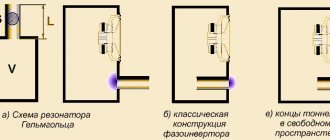
The principle of operation of a phase inverter
The essence of the operation of this device is that, with the help of an acoustic resonator, the phase of the sound wave emanating from the rear part of the diffuser is reversed (inverted).
At the output of the bass reflex, this already inverted wave is summed with the wave emitted by the front surface of the diffuser. This significantly increases the sound pressure level at the tuning frequency of the device. Advantages and disadvantages of FI
The advantages of this type of acoustic design are well known. Approximately 90% of modern speaker systems produced in the world are equipped with a bass reflex. The lower frequency limit in such systems is 1.26 times less than in closed analogues (with the same housing dimensions and efficiency).
If we take acoustics with the same dimensions and lower frequency limits, then systems with a bass reflex will have a 3 dB higher efficiency. And finally, with the same values of the lower limit of frequency and efficiency, the dimensions of such a system will be significantly smaller.
The disadvantages of a bass reflex include low transient characteristics (compared to closed-type systems) and a more complex process of matching the amplifier with the speaker system. That is, the duration of the attenuation and the rise time of the sound signal are determined only by the quality of the bass reflex itself. In practice, this manifests itself in the dull sound of the timpani, the “thumping” sound of the drum, blurred plucking when playing music from stringed instruments, etc.
It is worth noting that the advantages significantly outweigh the above-mentioned disadvantages. Therefore, most companies specializing in the production of audio equipment introduce this device into their models.
For a simple music lover - a user of acoustic systems - it is enough to know a few simple but very important things about the bass reflex. In a room less than 12 meters in area, you cannot install speakers with a bass reflex located in the rear - you will get a disgusting thump instead of music. For small rooms, it is better to choose speakers with a front-mounted bass reflex or without it at all. If your speakers are equipped with a bass reflex, and it seems to you that the bass is “booming”, try plugging the bass reflex hole with any thick rag - sometimes this helps.” ©
2.
Before you start calculating the FI, you need to measure the T/C parameters for the woofer. I see no point in repeating or copying everything into this review. Comprehensive description - How to measure the Thiel-Small parameters of speakers using a PC and select the right enclosure for them.
Selecting FI sizes (link to source).
Lots of text. Hidden under spoiler.
The logical ending to the saga of the bass reflex will be the practical aspects of its implementation. The key element here is precisely the pipe, which is also a tunnel, which, as a result of slavish transliteration from English, is also a port. It is this, the pipe, that will make it possible to implement in practice two main parameters that determine the acoustic appearance of the conceived bass reflex: the volume of the housing and its tuning frequency. These two values, one in liters, the second in hertz, are the result of either an independent calculation or following previously made calculations. Their source may be the speaker manufacturers, our tests, or expert advice based on their practice. In all three cases, it happens that ready-made tunnel dimensions are given, ensuring the tuning of a known volume to the desired frequency, but, firstly, not every time, and secondly, blind copying is not always possible and is always not commendable. So the following formulation of the problem will be more general and much more productive: the volume and frequency are known, and we will solve the question of their physical, material, implementation on our own. Part of the story will be organized according to the principle of questions and answers: the nomenclature of questions is known, in the editorial mail they are repeated with regularity, giving rise to statistical calculations that our testing department loves so much. I won’t take away their favorite toy, or ours. So, what first, do we calculate the tunnel or buy the pipe that will become this tunnel? In theory, you need to buy it first - the pipes do not come in any diameter, but from a certain range of values, if you take ready-made ones, and do not wind them yourself from paper with glue, like a pioneer from a young cosmonaut's circle. But you still have to start with at least a rough estimate, and the point here is that... Thickness matters
If the tunnel is really a pipe (there are options, after all), what diameter should it be? The most general and crudest answer is: the more, the better. The advice is really radical and can cause a protest reaction: what if I take and make a tunnel with a diameter twice the size of the speaker? You won’t take it and won’t do it, no matter how hard you try, this was taken care of more than a hundred years ago by a certain Hermann Helmholtz, whose resonator name the bass reflex is, and later by the creators of cars, who made them smaller in size than the steam locomotives that existed at that time. So, in order, why more and why something will stop this process. During operation near the tuning frequency, where, in fact, the bass reflex tunnel performs its functions, adding to the sound waves generated by the vibrations of the diffuser, air moves inside the tunnel. It moves oscillatingly, back and forth. The volume of moving air is exactly the same as that driven by the diffuser during each oscillation; it is equal to the product of the diffuser area and its stroke. For a tunnel, this volume is the product of the cross-sectional area and the air flow inside the tunnel. The cross-sectional area is actually always smaller than the diffuser area (if anyone has not yet given up the threat to make the same, or even larger, they will soon not go anywhere and refuse), and in order to move the same volume, the air needs to move faster, the speed in the tunnel decreases diameter increases in proportion to the decrease in its cross-sectional area. Why is this bad? Everyone at once. First of all, the Helmholtz resonator model, on which everything is based, assumes that there is no energy loss due to air friction against the tunnel walls. This, of course, is an ideal case, but the further we move away from it, the less the bass reflex operation will resemble what we expect from it. And the higher the air speed inside the tunnel, the higher the friction losses in the tunnel. Theoretically, the formula, and even the simple program based on it, does not take these losses into account and will meekly give you the estimated length of the tunnel with a diameter of even a finger, but such a bass reflex will not work, everything will die in the turbulence of the air trying to quickly fly backwards through the tight tunnel. forward. The text of a traffic police propaganda poster I once saw, “Speed is death,” certainly applies to the movement of air in a tunnel, if death is attributed to the effectiveness of the bass reflex.
However, much before the phasic dies as a means of sound reproduction, it will become a source of sounds for which it is not intended; vortices arising from excessively high air speeds will create jet noise that disrupts the harmony of bass sounds in the most unscrupulous and unaesthetic way.
What should be taken as the minimum cross-sectional area of the tunnel? You will find different recommendations in different sources, not all of them have ever been tested by the authors, even through a computational experiment, let alone others. As a rule, such recommendations include two values: the diameter of the diffuser and the maximum value of its stroke, that is, Xmax. This is reasonable and logical, but it fully applies only to the operation of the subwoofer at the maximum mode, when it is already a little late to talk about sound quality. Based on numerous practical observations, you can adopt a much simpler rule, it is not perfect and not entirely universal, but it works: for an 8-inch head the tunnel must be at least 5 cm in diameter, for a 10-inch -
7 cm, for 12 and more - 10 cm. Is it possible to have more? It’s even necessary, but right now something will stop us. Namely, the length of the tunnel. The point is... Length matters.
As was said, she will be commanded by the great Hermann von Helmholtz. Here he is, at the blackboard at the University of Heidelberg, and on the blackboard is the same formula. Well, okay, this time I wrote it, but I made it up - he would have written it exactly the same way. This simple dependence, since it was derived for the ideal case, shows what the resonance frequency of a certain cavity will be (we are more familiar with a box, although Hermann von made some kind of bubbles with pipe tails) depending on the volume V, length L and cross-sectional area of the tail. Please note: there are no speaker options here, and it would be strange if there were. In any case, it is useful to remember and never succumb to provocations: the bass reflex setting is completely and exhaustively determined by the size of the box and the characteristics of the tunnel connecting this box with the environment. In addition, the formula includes only the speed of sound in the atmosphere of planet Earth, designated “c,” and the number “pi,” which does not even depend on the planet.
For practical purposes, namely, calculating the length of the tunnel from known data, the formula can be easily transformed by remembering your native school, and the constants can be substituted in the form of numbers. Many people did this. Many people published the results of this exciting process, and the author is a little surprised how it was possible to screw up spectacularly during an operation with three or four numbers. In general, a third of the converted formulas published on paper and on the Internet are incomprehensibly nonsense. The correct one is given here if you substitute the values in the units shown in black.
The same formula, plus some corrections, is included in all known programs for calculating bass reflexes, but right now the formula is more convenient for us, everything is in sight. Look: what will happen if, instead of the minimalist tunnel, we install another, larger (and therefore better) one? The required length will increase in proportion to the square of the diameter (or in proportion to the area, but we were going to buy a pipe by diameter, they don’t sell it any other way). We switched from a 5-centimeter pipe to a 7-centimeter one, for example, the length with the same setting will need twice as much. We moved to 10 cm - four times. Trouble? So far, it’s not so bad. The point is... Caliber matters.
There will be trouble now. Let’s look at the formula again, this time look at the denominator, focus your vision. All other things being equal, the length of the tunnel will be greater, the smaller the volume of the box. If, in order to tune a 100-liter volume to 30 Hz, having a 100-mm plumbing pipe at your disposal, you need to open and paste a 25-centimeter piece of shit pipe into the box, then with a box volume of 50 liters it will be half a meter (which is no less, than not so bad), and with the fairly common 25 liters, a tunnel of this thickness will have to be a meter long. This is already a disaster, there are no options.
In our practical conditions, the volume of the box is primarily determined by the parameters of the speaker, and for reasons already well known to readers of this series, for 8-inch heads the optimal volume rarely exceeds 20 liters, for “ten” heads - 30 - 40, only when it comes reaches 12-inch caliber, we begin to deal with volumes of the order of 50 - 60 liters, and even then not always.
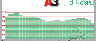
So we get some kind of parade of sovereignties: the FI tuning frequency is determined by the bass that we want to get from it, whether it’s on the “eight” or on the “fifteen” - it doesn’t matter. And the tuning frequency of the box again does not depend on the speaker; the smaller the volume, the longer the tunnel. The result of the parade: as we have repeatedly noticed in tests of small-caliber subwoofers, the desired and promising design option in FI is physically impossible (or difficult) to implement. Even if you don’t mind the space in the trunk, you cannot make the volume of the FI box larger than the optimal one, and the optimal one often turns out to be so small that setting it to a frequency of 30 - 40 Hz, which is invariant to other factors, is unthinkable. Here is an example from a recent test of 10-inch subwoofer heads (“A3” No. 11/2006): if we take a pipe diameter of 7 cm as an axiom, then in order to make a bass reflex on the Boston head, a piece of it 50 cm long would be needed, for Rainbow - 70 cm, and for Rockford Fosgate and Lightning Audio - about a meter. Compare with the recommendations in the test of this issue relating to 15-inch heads: none of these problems were noted. Why? Not because of the speaker, as such, but because of the initial volume selected according to the speaker parameters. What to do? Meet adversity head-on. Generations of specialists (and others) forged our weapons. Do you know what's the matter?
Shape matters
You could hardly fail to notice: I really like to delve into patents, because I believe that even though the road from invention to real life is not so short, a patent is a reflection of thought in the form of a vector, that is, taking into account the direction. Most of the innovations proposed (and steadily proposed) by tireless minds in relation to the bass reflex are concentrated on combating two interfering factors: the length of the tunnel, when its cross-section is large, and jet noise, when they tried to reduce its cross-section, trying to reduce the length. The first, simplest solution, the admissibility of which we are asked in our editorial mail about five times a month: is it possible to place the tunnel not inside the box, but outside? Here is the answer, final, factual and real, like a paper for Professor Preobrazhensky’s apartment: you can. At least partially, at least entirely, the tunnel was pushed inside the box solely for aesthetic reasons; von Helmholtz had it sticking out outside, and nothing, he survived it. And our modern times provide examples: for example, car audio veterans cannot help but remember (many, frankly speaking, cannot forget) the “bass pipes” of the SAS Bazooka company. They started with a patent for a subwoofer that could be conveniently placed behind the seat of a truck, America's favorite vehicle. To do this, the inventor stretched the bass reflex pipe along the body from the outside, at the same time giving it a shape spread out over the surface of the cylindrical body. This is one example, there is another: some companies that produce built-in subwoofers for home theaters bring out a pipe-tunnel of a bandpass subwoofer. The type of subwoofer in this case does not matter: it is the same resonator named after you know who. Judging by the letters, they are also looking for another solution, but they are afraid. “Is it possible to bend a tunnel?” The answer is in the style of Philip Philipovich and is obvious. Otherwise, several companies (DLS, JL Audio, Autoleads, etc. etc.) would not have produced flexible pipes specifically for this purpose. And in the field of patent documentation there is even an interesting hint on how this problem can be solved not without grace and material savings: at one time a design was proposed for a model tunnel that would be assembled from standard elements in any desired form; the illustration will tell the rest. I’ll add on my own behalf: most of the details depicted in the patent are touchingly reminiscent of the nomenclature of elements of local sewer networks, which is a practical recipe for introducing the intellectual excess of the American inventor.
When struggling with the inappropriate length of the tunnel, they often take the path of constructing so-called “slot ports”, their advantage lies in their structural integration with the body, which allows, with a certain imagination, to make the tunnel quite long; in the attached diagram there are several options at once, which the question is, Of course, it is far from being exhausted (the three top sketches belong to the pen of the famous high-end designer Alexander Klyachin, the rest was a matter of technique).
The disadvantage of the slots is that it is difficult to adjust the length, this is not plumbing PVC - waved the saw, and it was done. But there are solutions here too: not so long ago, one of the heroes of the “Own Game” column, Permian Alexander Sultanbekov (it’s not a sin to once again remind the country of the names of its heroes) demonstrated in practice how a slot port can be adjusted by changing its cross-section while maintaining a constant length, he I did it by placing plywood spacers inside, as shown in the photo somewhere nearby, look for it.
In folding the bass reflex tunnel, some bright minds went to extremes: one bright one suggested, for example, folding the tunnel in the form of a spiral around a cylindrical loudspeaker body, another responded to Helmholtz’s cunning formula with a screw tunnel, this concept is familiar to us here in Russia...
But in general, all these solutions (even with a propeller) are frontal; here a tunnel of constant length is simply attached or folded so that it does not interfere. Implementations of another principle are known (and even sold in commercial quantities). Here's the thing.
Section matters
Not the area as such, but the nature of its change along the length of the tunnel.
Until now, we, guided by the teachings of von Helmholtz in its simplest, school form, have considered it indispensable that the cross-section of the tunnel is constant. But there were people who violated this condition and even made money from it. ... A move away from the cylinder as a form of tunnel was proposed by many, many people. Some - in the style of Matarazzi with variations, some - on a modest, local scale, limiting themselves to giving curved contours to the ends of the cylindrical tunnel in order to reduce jet noise from turbulence. The most radical means of combating both length and noise was not only invented, but also exclusively used for many years by Matthew Polk, the founder of a company named after him. The essence of the device called PowerPort is this: part of the functions of the tunnel is taken over by one or two, at each end of the pipe, an annular slot between the wall of the box and a “fungus” placed at a strictly calculated distance from it, however, everything is visible in the figure. Almost all Polk Audio home speakers are equipped with such tunnels. And if someone encroaches, they pay him 32 cents plus something else. For yourself, your loved ones, no one will forbid you to try such a thing, especially since once upon a time Polk posted a table in Excel on his corporate website... On the issue of thickness: pushing the same volume of air through a tighter tunnel, it will have to be accelerated to higher speed. And “speed is death” Helmholtz would have written his formula in exactly the same way, but there was no photographer at that moment. © I hope I completely confused everyone.
Understand. Tried my best. ))) I’ll probably skip the process of building speakers with FI. There is enough for a dozen reviews with the choice of speakers, case materials, carpentry, assembly, etc.
3.
Formulas you will need. The formula for determining the resonant frequency of the speaker is the same for both the WY and the FI:
Personally, I find it enough to calculate FI and GL in the JBL Speakershop program.
“... In no program will a window pop up with the message - guy, of course, I’ll calculate everything the way you want, but you’re doing something stupid, and the sound will suck.” ©
Therefore, it will be useful to check the proposed dimensions of the FI and the body yourself using third-party calculations. For example, online calculation of FI.
4.
While writing the review, I came across the material Subwoofer with a bass reflex: calculation, setup, typical mistakes, in which the author very emotionally talks about the shortcomings of the acoustic design of the FI type. If you still want to build a sub or speaker with a bass reflex, the material is recommended for reading.
5.
Checking the FI settings.
The basis is the technique proposed at the link: measuring the modulus of total electrical resistance Z
of an acoustic system.
What should be the tuning frequency (resonance) of the bass reflex? The resonance frequency of the bass reflex (in general) should be 2/3 octave lower than the resonance frequency of the same speaker in the same box with the FI hole closed.
For example: Fc dynamics in the GZ = 60 Hz, then the tuning frequency FI d.b. 60/1.5874 = 60*0.63 = 37.8 (Hz)
Notice the number appears 0,63
- this is “2/3 octave lower”.
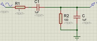
Initial connection diagram for the woofer (or speakers with FI):
Explanations (changes in the circuit): - it is recommended to use an amplifier that provides a minimum of 7.1 V RMS (10 V ampl.) - as a signal source for the amplifier - a software generator in SpectraLab - instead of a voltmeter - the line input of the PC sound card ( connect to the speaker !
).
Thus, only a 1 kOhm resistor is required
.
General procedure: - assemble a test circuit taking into account the explanations above - set the output level. signal in the system mixer 50-70% - set the volume control on the amplifier so that the output voltage is 7.1..10 V RMS without clipping - select a sweep tone in the settings of the software generator (range 20-200 Hz, if you need to check FI, or 20-20k Hz for the entire speaker range) - press the “let’s go” button)))
If everything is done correctly, you will get a picture like this:
6.
Checking the FI settings of the 11.8L subwoofer. Calculation in JBL Speakershop:
FI dimensions: f50x150mm
Checking calculations (online calculator):
According to T/S recommendations for FI sizes obtained from JBL, the FI tuning frequency is 57.7 Hz. According to Vinogradova’s recommendations, for the same FI sizes, a frequency of 52 Hz is obtained.
Calculation of the frequency Fc of the FD115-7 speaker in a 11.8L SG (this is not an error, we count it for a SG; see the formula in paragraph 4):
Fc = 67.5 * sqrt ( 1+ 2.66/11.8 ) = 74.7 (Hz)
Next, the circuit from step 5 is assembled. Result: subwoofer impedance module:
graph in orange - 11.8L sub with open FI graph in purple - 11.8L sub with closed FI (ZY 11.8L)
The difference in the frequencies of the two peaks - 2-3 Hz - is an indicator of the incorrect location of the FI in the housing: the cut of the FI pipe is located in close proximity to the back side of the speaker.
Conclusions: - FI tuning frequency - about 48 Hz, which is closer to the calculated value according to Vinogradova - frequency Fc = 82 Hz instead of the calculated 75 Hz - frequency ratio 48/82 = 0.59, which is close to the recommended value 0,63
For a training sub, I think it’s normal.
7.
Checking speakers with slot FI. In order not to be tormented by doubts, a homemade speaker system (project “Oak”) was tested using the same method.
I haven’t seen the calculations, and I’m not interested in it. Here's the result:
Tuning frequency FI 58 Hz, Fc = 105 Hz. Frequency ratio 58/105 = 0.55.
Conclusion: the slot-type FI turned out to be slightly below the -2/3 octave mark.
8.
And again SVEN. This time the BF-21R version with destroyed speakers and remote control (kinder chewed).
Of the four speakers, only one woofer survived.
A passive speaker took part in the experiments with FI (naturally, after replacing the woofer with a working one). After removing the speakers:
Using obscene expressions of magic spells, I picked out FI:
The inner diameter in the middle part is about 34 mm, length 75 mm. Note: the dimensions of the FI differ from the FI in the BF-11 version (f31 x 65 mm).
The internal volume of the BF-21 dispenser is 7.2 liters. Minus the volume occupied by the magnetic system of the woofer (0.2 l) and the FI tube (0.1 l), the volume of the speaker is 6.9 liters
.
We calculate Fc using the formula above: Fc = 67.5 * sqtr (1 + 2.66/6.9) = 79,5
(Hz)
Launch JBL Speakershop:
For diameter FI f34mm, the proposed length is 12.4 cm.
For one thing, let’s pay attention to the calculation for a 6.9-liter tank: Fc=79,4
Hz (same as manual value).
Checking calculations in an online calculator:
By T/S: 56.2 Hz By Vinogradova: 51.5 Hz
And so, it is required to lengthen the FI pipe by 5 cm (to a length of 12.5 cm). A cylindrical bottle of pills was found in the house:
Cat and pills
Sawed in half:
I shortened the pieces of tubes to 5 cm, connected them to the FI using the remains of electrical tape:
Length 12.5 cm.
After assembly, checking the FI settings:
Tuning frequency FI 49 Hz (versus the calculated 51.5 Hz according to Vinogradova), Fc = 81 Hz (almost coincided with the calculated value 79.5 Hz). Frequency ratio 49/81 = 0.61. Everything is OK here.
9. Conclusions:
- the Z measurement method is quite workable, you can use it - calculation methods predict how Gismeteo gives out contradictory figures - FI calculation can be performed in the JBL Speakershop program - it is recommended to check FI calculations according to E. L. Vinogradova - checking the FI settings using the Z method produces numbers, very close to those obtained from the calculations of E. L. Vinogradova
Using the Z method, the FI settings of three homemade speakers were tested. The results are positive. ))
10. Application
for Sound apologists who uncontrollably but stupidly remove the frequency response of the subwoofer (copy-paste). I will introduce you to the direct measurement method, which, unlike the computer one, does not require calculations and gives a more reliable result. Removing the frequency response of a subwoofer is carried out in an ABSOLUTELY quiet room, the entire internal surface of which is lined with mattresses, and in two layers. But it’s easier to do this in an open space, so that the nearest garage with an outlet is at least 10 meters away. If the speaker or FI is directed towards the floor, we place the subwoofer on the ground, on a shield; if not, we sit it like a person, on a stool. The measuring microphone should be installed on the side of the speaker and the FI at the same time, at approximately the same distance, and no closer than 1-1.5 meters from the subwoofer body. In this case, you will measure the combined sound pressure of the speaker and the FI. When you level out the frequency response of the subwoofer in an open space, only after that you can bring it into the room and identify the influence of the room on the resulting frequency response. Before that, I think removing the frequency response of the subwoofer in the near field and bringing the microphone 1 cm closer to the speaker is premature. And not necessary at all: you don’t put your ear to the subwoofer speaker and don’t listen to the subwoofer “in the near field” while lying on the floor? This is not midrange or high frequency, which are measured and listened to within line of sight, this is Bass. I strongly doubt that you will be able to correctly connect (merge) the frequency response of the speaker and the FI filmed separately in near fields. You will not get a true picture of the total sound pressure FI and dyna in the space surrounding the subwoofer by moving the graphs across the computer screen and the sub around the room. So guys, go out into the fresh air, onto the grass. It will be more beneficial for both music and health, because... Measurements should be carried out in warm weather so that the Dean’s suspension does not become stiff.
But this is not the end. The game will continue when you bring the tuned sub into the room and start butting heads with room resonances and modes. Very exciting. This is another disadvantage of a subwoofer with FI: it is capricious about its location in the room. A small displacement of the subwoofer leads to a noticeable change in room resonances, while a subwoofer of the ZYA type practically doesn’t care where to stand, as long as the symmetry of the sound is not broken.
Subwoofers with a bass reflex are some kind of misunderstanding, a play of the imagination of acoustic engineers, which was picked up and developed by music businessmen. The fashion is so audiophile: yes, I have FI pipes in my subwoofer, like exhaust pipes in a cool car! Even the sound is similar. Let me explain. It is pointless, and sometimes even harmful, to connect a sub with FI to the receiver to watch movies and some types of music. The DVD signal contains frequencies from 5 hertz. All the power of the receiver below the FI tuning frequency (from 5 to 30-40 Hz) is aimed at vomiting the speaker diffuser onto the floor. The sub does not make any sounds in this band; in addition, the speaker can be damaged. If the receiver or sub amplifier has a subsonic filter, then the speaker and diffuser will remain intact, but the sub will still not produce sounds from 5 to 30-40 Hz. Question: why then fence FI?? Is it for pop music? But for music, the sub-ZY is much better, besides, it reproduces frequencies lower than FI and does not peddle. The sub-ZY does not mumble, it has a smaller group delay, excellent transient characteristics, it is easier to calculate and does not require tuning. And I don’t care about efficiency, I’m not going to skimp on the volume and quality of the music 30 watts from the outlet. So, in all respects, a ZYa type sub is better than a FI. BUT! Only on the condition that the radio station has a good, high-quality speaker with a resonance F of 18-25 Hz, preferably with a low diffuser mass (and possibly a double power reserve for the Linkwitz corrector). Now we come to the point. The Chinese don't know how to make speakers like this, and good European speakers aren't cheap. The conclusion is obvious: FI type subwoofers almost certainly have a lousy speaker and the sub has all the disadvantages listed above. But it makes a loud noise, is cheap for the undemanding consumer (and that’s the majority of them), and you can make a profitable business out of it. Mass business. A subwoofer with FI is a cheap product for those who are hard of hearing, stingy or needy. The acoustic bass reflex was invented by Albert Turas in 1932, at a time when there were no decent bass speakers, but why now? In the days of vinyl and live instruments with a lower frequency of 30-40 Hz, a bass reflex was very useful. But in the age of electronic synthesizers and DVD recording, when the range goes into the infrasound region, the bass reflex is, to put it mildly, outdated and unable to reproduce the modern frequency range. A subwoofer with FI is an atavism, a relic of the past. Let me remind you once again: a bass reflex is a resonator. For listening to music, acoustic resonances are a harmful and unpleasant thing, they try to get rid of them in all sorts of ways: damping, equalization, filters, etc. But just take it and embed a didgeridoo into the subwoofer with your own hands..? And then reassure yourself that everything sounds good? No, excuse me. My personal preference: sub ZY. The presence of FI can be to some extent justified by its use in small-sized acoustics, but this is no longer Sound, and certainly not Bass. The only use for a subwoofer with a bass reflex with minimal damage to sound quality is to simulate explosive and thunder-like effects in movies and toys. There the high efficiency justifies itself. For music, FI is unacceptable. IMHO. ©
Happy development everyone!
Coming soon to our screens:
How the device works
Any bass reflex type speaker has a hole - a bass reflex. This is often called an acoustic tunnel or port. Its operating principle is to change the phase of the sound vibration caused by the rear side of the diffuser by one hundred and eighty degrees. When resonance occurs in the box, the vibration amplitude of the diffuser reaches a minimum value.
This is due to the fact that when moving forward, the speaker creates a vacuum in the middle of the closed column, thereby displacing air into the bass reflex channel and increasing the vacuum. Therefore, at the resonance frequency, mechanical waves are emitted through the hole, and not from the speaker cone.
The volume of air and the resonance frequency to which the channel is tuned depend on the size and type of the bass reflex port. The volume of air in the channel begins to resonate and enhance frequency reproduction when the moment comes when the diffuser emits the frequency for which the bass reflex is designed.
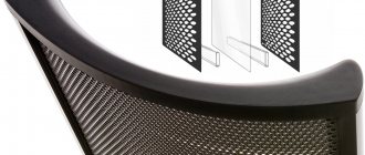
The classic tunnel is circular in shape. But to increase the useful internal area, it is often given a slotted appearance. Refusal of the cylindrical shape of the tunnel makes it possible to reduce its length and reduce the noise that occurs when air is released.
If there are errors in the calculation of a slotted bass reflex, it is much more difficult to configure it than the classic type, since it is manufactured together with the speaker. The calculation itself is more complicated than for closed-type systems: in addition to the volume of the box, the adjustable resonance frequency is taken into account. The optimal dimensions are selected taking into account the amplitude-frequency characteristics of the speaker, namely its uniformity.
Types of bass reflexes
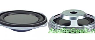
The bass reflex port is the main element of the body; it can be round (pipe) or rectangular (slit).
Slot port
Round port (pipe)
It is impossible to say for sure which of these ports is better. They do what is more convenient or what they like best. The only point is that in sports (sound pressure competitions) pipes are used more often , since their use makes it easier to change the bass reflex setting by changing the length of the port.
You can learn more about the nuances from our video about the difference between a pipe and a slot for a subwoofer:
Separately, it is worth noting this type as a passive radiator. A passive radiator (more correctly, a passive reflector) is the same bass reflex and the principle of its operation is the same. It is used in cases where the desired port for the FI does not suit the dimensions. A passive radiator uses a speaker without a magnetic system instead of a port .
Operating principle of a passive radiator
Peculiarities
Materials
Requirements for materials and assembly are standard. The bass reflex box must be strong, sealed and not vibrate. Material - plywood or MDF from 18 mm. and thicker.
Please note that all wire entry channels, terminal blocks, etc. must be reliably sealed , internal partitions (port walls) must not have any gaps .
Rounding of the bass reflex port
If the slot port is long and has turns, then stagnation zones may appear in the corners; to avoid this, the bends are smoothed out - as a result, efficiency increases, since the resistance to air movement decreases . It is quite difficult to determine the improvement in quality by ear, but for the fight for a high result in sound pressure, this solution works.
Port smoothing options
The ends of the ports can open up, which can eliminate parasitic noise from air friction at the outlet, but this problem is not common. It is worth remembering that due to the openings at the ends, the tuning of the port (bass reflex) increases, or its total length increases. That is, for the same setup, a port with extensions at the ends will be longer than a straight one and take up a little more volume.
Slot Port Expansion
Pipe expansion
Practical video on rolling out a pipe for a port:
It is worth understanding that selecting the correct expansion (opening) geometry is a separate task when calculating the bass reflex housing.
Which speaker is suitable for a bass reflex
To choose a subwoofer for a bass reflex, you need to start from the Thiel-Small parameters (Fs, Qts, Vas). Usually this data is in the documents, but if you don’t have it, the parameters can be found on the Internet.
In order to understand whether the speaker is suitable for FI, carry out some simple calculations. Divide the value by the Qts and if the answer is between 60 and 100, then such a sub will be optimal for a bass reflex.
For example, the SUNDOWN AUDIO E-12 V3 speaker has Fs = 32.4 Hz, and Qts = 0.37.
Fs / Qts = 32.4 / 0.37 = 87.6 - such a subwoofer is quite suitable for FI.
If the value for your speaker is outside the range of 60-100, it may be worth finding a different design for it using. Please note that the table above does not prohibit the use of speaker enclosures that do not meet the Fs / Qts value. She shows options that will definitely work well.
Low frequency tunnel calculation
There are several ways to calculate FI sizes. The most popular is to calculate the bass reflex online or using specialized programs. Such methods usually require knowledge of many parameters of the speakers used. There are simpler options, but with a large discrepancy between the final result and the real value. Although in any case, after calculation and manufacturing, adjustments have to be made.
Simple formula to calculate
The calculation method involves the use of simple formulas and is carried out using the data selection method, when the desired length of the FI channel is used as a basis.
F = (C/2 π) * K, where:
- F is the desired tuning frequency;
- C is the speed of sound;
- π is a mathematical constant equal to 3.14;
- K is a coefficient depending on the size of the bass reflex.
In this case, the K coefficient is equal to the square root of the S/LV ratio, where:
- S—hole area;
- L—channel length;
- V is the volume of the column.
Meters are used everywhere as units of measurement, and hertz is used for frequency. When determining volume values, it is believed that it is better to choose a narrow bass reflex, but this approach is incorrect, because at the same time the speed of air movement in it increases, and this introduces distortion into the sound. Designing a wide and long FI is also meaningless, because the length of the bass reflex should not exceed the wavelength at the moment of resonance. Following this rule helps to get rid of standing waves.
Using specialized programs
There are many programs that allow you to automate calculations when building speaker systems, for example, Bassport.
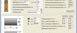
This program is specially designed to automate the calculation of the bass reflex port. When developing the program, it was taken into account that when the air flow speed in the pipe becomes more than six meters per second, noise becomes noticeable. The program interface is intuitive, especially since it is localized in Russian. To get the desired results you will need to enter:
- sound speed;
- column volume;
- bass reflex and speaker frequency;
- diffuser diameter;
- diffuser stroke.
After entering all the data, all that remains is to click the “Recalculate” button and get the result corresponding to the maximum quality factor, which depends, first of all, on the ratio of the volume of the box to the diameter of the port. The Bassport program allows you to perform calculations for various shapes, but most often, for flow velocities up to six meters per second, a simple shape for a tubular or slotted type is used.
It is necessary to note the following nuances when using the program. The diffuser diameter is measured between distances opposite the midpoints of the suspensions. The color of the flow speed figure indicates possible noise occurrences: black - no noise, red - noticeably audible noise.
The use of online programs is based on the same principle: system parameters are entered and the result is displayed. Sites with such programs can easily be found by searching for “bass reflex online calculator” in any search engine. Although, to ensure the reliability of the results, the data obtained should be double-checked on several sites.
After completing the calculations, all that remains is to manufacture and configure the bass reflex. It is not difficult to perform such operations at home, and no special materials are needed.