Probably one of the simplest homemade products that can seriously save money is a subwoofer. As a rule, you have to pay only for a large and high-quality low-frequency speaker; everything else can be easily found in a home workshop, or in the bins of a friend “Uncle Vasya”. Guided by these thoughts, it was decided to assemble the subwoofer with our own hands.
The speaker was available at 15″ and after carrying out the appropriate calculations, the following initial data came out:
- Box type: bass reflex
- Volume – 114 l
- Tuning frequency – 45 Hz
- Material – chipboard 18 mm
- Damping – no (not required)
- Passive filters - no (crossover required)
- Speaker – B&C 15PS100 8 Ohm, 700 W RMS
We won’t give all the calculations here; if you need details, look at how this is done in a similar subwoofer.
Subwoofer speaker parameters
Here are its characteristics:
- Nominal resistance - 4 ohms
- Peak power - 800 W (30-1000 Hz)
- Constant power - 500 W (30-1000 Hz)
- RMS power: 650W
- Sensitivity (2.83V/1m) - 96.5dB
- Coil diameter - 75 mm
- Magnet - Ferrite
- Housing - Aluminum
- Membrane - modified cellulose
- Mounting hole - 362 mm
- Hole diameter - 370 mm - 8 x 6.5 mm
- Total depth - 183 mm
- Net weight - 6.5 kg
- Outer diameter - 388 mm
List of subwoofer materials and components
- Speaker SW.STX.15.3.800.4.FAMC
- Handles x 2
- Corners x 8
- Lattice
- Tunnels BR x 2
- Carpet adhesive
- SPEAKON cable 10 m
- Plywood 18 mm
- Internal cable
- Black screws
- Upholstery material and legs
As for the speaker, it looks pretty good, although the manufacturer could have thought a little more about its design in terms of protection from dust and dirt getting inside.
There is a hole at the back of the speaker, about 6 cm in diameter, through which you can touch the coil housing, and there is no protection in the form of a sponge or other material to protect against dust.
Another visual disadvantage of the loudspeaker is the basket, which could have been made with more precision, because in some places you can see the curvature of the shape, although they are so small that you need to look closely to see them.
Body - 18 mm plywood, dimensions: height x width x depth 510 x 440 x 410 mm, net volume 92 l. BR tunnels with internal 75 mm and 85 mm length. Approximately 45 Hz setting. In the middle is a strengthening cross. The loudspeaker is secured with black M6 screws and nuts.
As for the sound, I can only say that at home (I haven’t had the opportunity to test it in a concert hall yet) it absolutely thunders, the sound is really very low. There is no crossover, and to cut off the mid and high frequencies, the signal is passed through a ULF equalizer.
In general, such a case would be suitable for a neater speaker than this STX. Now I'm looking forward to the big room experience and effects associated with this speaker at full power. In short, despite its simplicity and without any inventive innovations, the sound of the subwoofer is very positive. If you need detailed drawings and calculations for a 15″ box, see them here.
Source
In this article we will talk about a subwoofer based on the well-known and widespread speaker 75GDN.
Dynamic head
So, I almost got a 75GDN dynamic head for nothing, although it’s not in very good condition and in poor appearance, the whole speaker was covered with gunpowder, the dustproof cap was cut out of cardboard, and not very evenly.
I had experience repairing speakers, so I simply couldn’t leave it in this condition, so I decided to make a small upgrade. So I took the speaker apart. I will not describe all the details of this process; this is done using a solvent, improvised tools, such as a screwdriver, tweezers and straight hands.
In the speaker basket, for better cooling of the coil, 8 holes with a diameter of 8 mm were made. Then the basket was sanded, the places where the centering washer and suspension were glued were sealed with electrical tape and painted. Gold plated clips were also supplied.
The speaker cone was cleaned of dust and glue residue, sanded, and a new, flat field-protective cap (cut from cardboard) was glued on. After which, the head was reassembled. The speaker cone was covered with a layer of PVA glue and also painted. A decorative sticker for the cap was made from colored adhesive film.
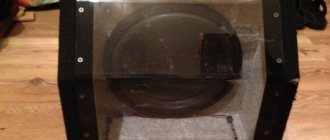
The speaker is finished, you can start making the box. Subwoofer housing
The body is made of furniture-grade, laminated chipboard 16mm thick. There are two stiffening partitions inside. The side walls are recessed to improve the appearance and ease of pulling the sub. The front wall is thickened, 32mm thick, glued together from two chipboard boards. There is also a hole in the front where the indicator board is placed, and there is also a recess for the head to fit. The walls of the case are connected to each other with screws and glued with PVA glue, and there is also 20x20mm timber around the entire perimeter inside. An additional, separate compartment is made in the side wall where the amplifier is located. Net volume is about 40 liters.
The inside of the sub is covered with 10mm thick foam rubber of medium density. It is better to adjust the bass reflex by ear, since the TC parameters of the speakers may differ. Its internal diameter is 70mm, the length of the port can vary from 18 to 25 cm with a frequency setting of 30-40 Hz.
In principle, the box turned out to be quite strong and solid, although it might be worth making the side walls a little thicker, for example 18mm. The top of the sub is covered with black carpet.
Electronics
Amplifier
The amplifier circuit is shown below
You can read about the operation of the circuit in the article “Car amplifier monoblock” or directly in the article by the author of the circuit in the magazine “Radio”. The only thing that has changed is the circuit board. The amplifier does not require any adjustment, everything works from the first turn on.
Voltage converter and stabilizer
The voltage converter and stabilizer circuit also remained unchanged. The only thing that has changed is the circuit boards and another 15V voltage regulator has been added to power the output power indicator. The converter and stabilizer are mounted on two boards measuring 160x85mm and 45x50mm, respectively.
I will also not delve into the operation of the circuit, however, from the experience of the previous article, I will tell you again about winding the transformer, since due to the lack of photos many questions arose.
The transformer is wound on a ferrite ring with dimensions 40x25x11. First, all sharp edges of the ring are rounded off with a file and wrapped with rag tape.
The primary winding is wound with 5 strands of 0.8-0.9mm wire and contains 2x6 turns. The first half of the winding is wound first; it is evenly distributed throughout the entire ring.
Then the second one.
At the ends the wires are twisted and 4 pins come out. We bend these leads under the holes in the board and wrap the primary winding with the same electrical tape.
Now you can take on the secondary winding, in my version it is wound with 1.5mm wire and contains 2x16 turns, wound in the same way as the primary winding. As a result, we get 4 more outputs of the secondary winding.
We bend it under the board and wrap it with electrical tape. The transformer is ready, we clean the leads and solder them onto the printed circuit board.
Also, perhaps it is worth introducing output chokes into the circuit on each power arm; they can be wound on ferrite rods 2 cm high and 8 mm in diameter and contain 6-8 turns of 1.2-1.8 mm wire. The input choke is wound on a ferrite ring from a computer power supply with two 1mm wires and contains 10 turns evenly distributed on the ring.
The assembled stabilizer board looks like this:
Filter block
Still the same filter scheme, tested 100 times by me:
Output power indicator
The output power indicator is assembled on the LM3915 chip according to the following circuit.
S1 switches the operating mode of the indicator: when the contact is closed, the “column” mode, and when the contact is open, “wave”. Using trimmer resistor R5 you can set the desired indicator level. In principle, any LEDs can be used.
Design and installation
Since there wasn’t much space allocated for electronics, it wasn’t so easy to “shove” it in there; we had to be clever. Consequently, all boards, connectors and control knobs are mounted on an 8mm thick MDF plate. The radiator, power and REM terminals, input sockets, as well as filter unit regulators are located on the outside. Externally, this plate together with the radiator is painted black. From the inside, in the place where the transistors should be attached, a rectangular hole was made in the plate. A duralumin plate was cut along this hole in order to “build up” the radiator to the required level and make it convenient to mount the transistors. This plate is screwed to the radiator with two bolts; between the plate and the radiator there is naturally a layer of thermoplastic. The bolts are deliberately left longer, since later a duralumin plate is placed on them, which presses all the transistors to the radiator. (The photo shows the first version of the amplifier, one TDA7294 without transistors. The circuit did not show itself, so another PA was later implemented)
The converter board is attached to MDF plastic using duralumin corners, two small ones are directly screwed to the board and plate, and two large ones are removed from the board and with the help of 2 stretchers made of copper wire do not allow the board to swing.
A plastic corner is made for the power amplifier board, which supports one part of it, but it is mainly held in place by the output transistors and the microcircuit, which are tightly pressed to the radiator with a duralumin plate. Between the radiator, the microcircuit and all output transistors there must be a dielectric plate and, of course, thermal paste, the transistor housings and microcircuits are isolated from the radiator.
The stabilizer board is attached to two plastic corners, and the filter board is held in place using duralumin plastic, to which three regulators are screwed.
The wires from the power terminals to the voltage supply board are as thick as possible, at least 4-6 sq. mm. An 8-pin connector is used to connect the indicator board and subwoofer operation indicators. Also, for convenience, you can introduce a 2-pin connector to connect the dynamic head.
The output power indicator board and power indicators are fixed in a designated place, the holes for the wires are sealed with plasticine after installation. The indicators are covered with a darkened glass plate.
Final result
At that time I was satisfied with the end result. The subwoofer played a very soft, pleasant and deep bass and could create quite good sound pressure for a 10. However, he didn’t have time to play with me for long, because after buying the car it was planned to build another system with a different subwoofer. This subwoofer was sold and to this day it pleases the new owner.
Author: Alexander Korchinsky (Email address is being protected from spambots. To view the address, your browser must have JavaScript enabled.)
Box drawing for 15 inch subwoofer
The 15-inch woofers are the most powerful of the range. Individual loudspeakers “pump” power in excess of 1,000 watts, so when calculating and designing such systems, increased requirements must be met. A box for a 15 subwoofer must have a rigid body and strong connections of individual elements. If the box can be assembled using self-tapping screws, then it is best to mount the loudspeaker on cage nuts, since strong vibration can cause the screws to come out of their seats and the system will collapse.
How to calculate a box for a 15-inch subwoofer
If the size of the luggage compartment of the car allows, then you can implement a box with a bass reflex. The biggest advantage of such a system is a noticeable increase in efficiency. In order to get the most out of a speaker in a closed box, you have to deliver maximum power from the amplifier. In bass reflex designs, the output power, and therefore the efficiency, increases due to the use of forward and reverse stroke of the speaker cone. In closed systems, sound is emitted only by the front plane of the loudspeaker, and the return radiation is damped inside the box. Calculations for a 15-inch subwoofer box include the area of the bass reflex port. These are complex calculations, so when making a bass reflex box yourself, it is best to use ready-made diagrams and drawings. You can also use the JBL Speaker shop, Bass Port or Box Plot computer program.
How to make a housing for a subwoofer with your own hands
If you need to make a good box for a subwoofer, then it is best to focus on the most complex design. This system is called a bandpass. It comes in fourth order and sixth order. The fourth-order system is a two-chamber box, where one chamber is a closed box, and the other plays the role of a bass reflex.
A sixth-order bandpass is a design with two bass reflexes. The most difficult thing here is the calculation of the second port and the relative relationship of the settings of each bass reflex. The two chambers have different sizes and are capable of limiting the frequencies reproduced by the loudspeaker. The box for two subwoofers is the most difficult to design, but it has the maximum efficiency. To determine all sizes of such sound systems, special utilities are used. The universal WinISD program is suitable for calculating any subwoofer design. It does not have a Russian-language interface, but it is not difficult to understand. To make a drawing of a box for a subwoofer, just load the parameters of the speaker you are using into your computer.
Drawings for a 15 subwoofer on a pipe
A low-frequency speaker with a bass reflex in the form of a piece of hollow pipe is easier to manufacture than a sound system with a slot bass reflex. The drawing of a 15-inch subwoofer does not contain complex details. All body elements are cut from thick plywood or MDF with a thickness of 18-25 mm. A hole is cut in the front wall for the loudspeaker. The second hole for the cylindrical port can be made in the front or top wall, depending on the design features of the column. You can buy a ready-made industrial speaker, but practice shows that a home-made device often has better characteristics than a branded sample. Polypropylene sewer pipes are used as a pipe for a homemade acoustic system. They are dark gray in color and come in several sizes. The port size is calculated based on the type of speaker. Adjusting the bass reflex port involves changing the length of the pipe. The shorter the cylinder, the higher the frequency.
Selecting speakers for a subwoofer
Speakers compatible with the case can be used: 18Sound 18LW2400, B&C 18TBX100, RCF 18X401 or their parametric equivalents. In general, it is not at all difficult to choose a suitable speaker for this case. The vast majority of decent 18's will play well here, except for the cheap no-names and those with Qts above 0.4.
The subwoofer weighs about 45 kg. That's why there are handles on the sides: it's convenient for carrying. The center of gravity is shifted 265 mm from the rear edge.
A selection of speakers for a homemade portable speaker
When assembling homemade portable acoustics, the question arises - what speakers to use? Aliexpress has a large selection. But for portable solutions there are proven options and their own requirements.
Speaker requirements for portable acoustics:
- Preferably a neodymium magnet (more powerful, more compact, more efficient)
- Preferably a diffuser with moisture protection
- Rubber wide surround (stronger, more durable, longer speaker travel)
- It is better to take 4 ohm speakers than 8 ohms, since the amplifier will deliver more power to such a load
To protect against external influences, it is recommended to use protective nets.
Consider broadband and low-frequency options with a large number of orders, ranked by increasing size and power.
AIYIMA 1.5 inches
Open a selection of speakers from the AIYIMA brand measuring 1.5″ (diameter: 40 mm). For near-field micro speakers on one 18650 battery.
High quality speakers, neodymium magnets. There is a normal flange for mounting 4 screws.
You can use a computer fan grill (60 mm is suitable) as a protective mesh.
The lot has an option of 5 and 10 W, if you are using a PAM type amplifier powered by one 18650, it is better to save money and take 5 W.
MACGARSEN 2 inches
The speaker has a similar design, but is slightly larger in size. 2" 53 mm. Power 10 W maximum, neodymium magnet, 4 Ohm resistance, sold in pairs.
This is roughly what Chinese brands install in small portable speakers.
For this size they have a fairly low resonance of about 130 Hz, and can produce good bass for a “portable” if you add a passive radiator.
Vifa NE65W-04
Interesting branded (Tymphany) 2″ speaker. 20 W! Aluminum diffuser and basket, powerful magnetic system. Smooth frequency response in the voice range. These babies definitely won't disappoint with their sound.
The speaker parameters (Thiel-Small parameters) are given on the product page from the company's catalog; you can rely on them to calculate the acoustic design of the speakers.
There are a couple of devices in the lot. Yes, it won't be cheap, but it is the solution for portable HiFi audio.
Peerless P830986
Another branded speaker, but in the most popular size 3″ (75 mm).
Diffuser and cap made of anodized aluminum film, plastic basket, neodymium magnet. Wide rubber suspension. Resonance below 100 Hz.
Parameters for acoustic design are given on the product pages. I was making about a 1.7L closed box with damping. At this size, you need to make an isolated volume for each speaker.
I made a boombox on these speakers, the sound is tonally even, vocals sound nice. I recommend. Small stationary desktop systems are also suitable.
Housing drawings and element dimensions
- Top base – 675 x 437 mm
- lower base – 675 x 437 mm
- left side – 675 x 550 mm
- right side – 675 x 550 mm
- rear panel – 400 x 550 mm
- front panel – 400 x 450 x 50 mm
- reflective wall horizontal – 400 x 382 mm
- reflective basin – 100 x 400 mm
Box finish: black matte nitrocellulose varnish Nitromal, spray with a large nozzle, which gave the effect of the desired texture.
Useful: Simple passive subwoofer (with calculations and photos)
The costs for a homemade 15″ sub were mainly for the speaker - about 14,000 rubles, but you can find it cheaper, it all depends on the brand and store. Power tools were used for the work: drill, jigsaw, milling cutter, vibrating grinder, compressor and paint gun.
LF ACOUSTICS ON 15″ SPEAKERS
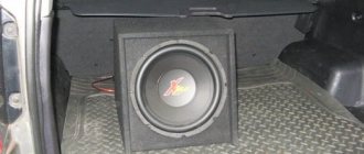
Hello everyone, here is another design for bass speakers, perhaps it will be useful to someone and inspire them to build something similar with their own hands. These speakers were made quite a long time ago, about a year ago, and since then they have been working faithfully for the benefit of my ears)).
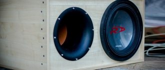
The speakers used are two 15-inch (38 cm) Alpharda PS15 heads. This speaker is really more suitable for 2/3 channel speakers. But I really wanted a subwoofer, since there is never too much bass (unlike mid-high frequencies).
The entire structure is made of 18 mm chipboard, there was no support in the middle. If someone wants to make a similar sub, it is still better to strengthen it. Glued and screwed every 5 cm. Filling 2 cm with sponge. The column is covered in leather.
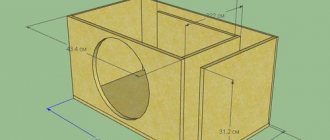
- Height: 54 cm.
- Width: 46 cm.
- Depth: 54 cm.
The front part was moved back about 3 cm.
I set the speaker to 40 Hz, I don’t remember exactly the length of the bass reflector. The loudspeaker itself had a volume of 110 liters.
Cost estimate for subwoofer assembly
- Acoustic systems Alphard PS15 — 5000 rub.
- Boards - 100 rub.
- Refill - 100 rub.
- Glue, screws - 100 rub.
- Leather covering - 1000 rub.
- Terminals, holders, corners - 100 rubles.
- Cable in a speaker - 50 rub.
Everything turned out to be about 10,000 rubles for 2 pieces. For high-quality subwoofers, 15″ is quite a bit. And most importantly, the finished speakers fit perfectly into the interior, both in color and shape. It would definitely not be possible to buy such ready-made ones.
Source