What is a DAC and how does it work?
A digital-to-analog converter is a device that converts a digital signal in the form of binary code into an analog signal in the form of current, voltage or charge.
In smartphones, computers and players, the converter is a chip with a stereo output on a ⅛” or RCA connector.
More complex converters are already stand-alone devices with the ability to connect to computers or audio systems, with a large number of channels and connectors. Converters differ from each other in the quality and accuracy of signal transmission.
Any DAC works with binary code. The device converts the code into an electrical signal: one corresponds to the presence of voltage; at zero there is no voltage. After this, the electrical signal is sent to the speaker system, where it is converted into sound vibrations.
Methods for implementing a DAC with weighted summation of currents
Let's consider the construction of a simple DAC with weighted summation of currents. This DAC consists of a set of resistors and a set of switches. The number of keys and the number of resistors is equal to the number of bits n of the input code. Resistor values are selected in accordance with the binary law. If R = 3 Ohms, then 2R = 6 Ohms, 4R = 12 Ohms, and so on, i.e. Each subsequent resistor is 2 times larger than the previous one. When a voltage source is connected and the switches are closed, current will flow through each resistor. The current values of the resistors, thanks to the appropriate choice of their ratings, will also be distributed according to the binary law. When the input code Nin is submitted, the keys are turned on in accordance with the value of the corresponding bits of the input code.
It will be interesting➡ Why do you need a frequency converter
The key is closed if the corresponding bit is equal to one. In this case, currents are summed up in the node, proportional to the weights of these bits, and the value of the current flowing from the node as a whole will be proportional to the value of the input code Nin. The resistance of the matrix resistors is chosen to be quite large (tens of kOhms). Therefore, for most practical cases, the DAC plays the role of a current source for the load. If it is necessary to obtain voltage at the output of the converter, then a current-voltage converter is installed at the output of such a DAC, for example, on an operational amplifier.
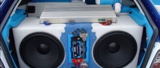
DAC board.
However, when the code changes at the DAC inputs, the amount of current taken from the reference voltage source changes. This is the main disadvantage of this method of constructing a DAC. This construction method can only be used if the reference voltage source has low internal resistance. In another case, at the moment the input code is changed, the current taken from the source changes, which leads to a change in the voltage drop across its internal resistance and, in turn, to an additional change in the output current not directly related to the code change. The structure of the DAC with switching switches allows this drawback to be eliminated.
Four-bit DAC signal table (5 V reference voltage).
In such a structure there are two output nodes. Depending on the value of the bits of the input code, the corresponding keys are connected to the node connected to the output of the device, or to another node, which is most often grounded. In this case, current flows constantly through each resistor of the matrix, regardless of the position of the switch, and the amount of current consumed from the reference voltage source is constant.
A common disadvantage of both structures considered is the large ratio between the smallest and largest values of the matrix resistors. At the same time, despite the large difference in resistor ratings, it is necessary to ensure the same absolute accuracy of fit for both the largest and the smallest resistor rating. In an integrated DAC design with more than 10 bits, this is quite difficult to achieve.
Structures based on resistive R-2R matrices are free from all of the above disadvantages. With this construction of the resistive matrix, the current in each subsequent parallel branch is two times less than in the previous one. The presence of only two resistor values in the matrix makes it quite easy to adjust their values.
The output current for each of the presented structures is simultaneously proportional not only to the value of the input code, but also to the value of the reference voltage. It is often said that it is proportional to the product of these two quantities. Therefore, such DACs are called multipliers. All DACs will have these properties, in which the formation of weighted current values corresponding to the discharge weights is carried out using resistive matrices.
Additional material on the topic:
Integrated technologies make it quite simple to form resistors on a chip, for example, CMOS technology. Like all other ICs created on its basis, such DACs are characterized by low cost and low consumption. The disadvantage of this technology is parasitic capacitances, and the resulting low performance. Bipolar technology will help achieve greater performance. BUT it is not designed for creating precise resistors.
Therefore, when using such technologies, the DAC is made on the basis of transistor current sources. The dependence of the output current of transistor current sources on the supply voltage is nonlinear, therefore such DACs are not multiplying. In addition to being used for their intended purpose, multiplying DACs are used as analog-to-digital multipliers, as code-controlled resistances and conductivities. They are widely used as components in the construction of code-controlled (tunable) amplifiers, filters, reference voltage sources, signal conditioners, etc.
Digital-to-analog converter.
Characteristics
The DAC largely determines the parameters of the entire audio system and directly affects the quality of the resulting audio signal.
The main parameters of the quality level of recording in digital format are: sampling frequency (measured in Hz), bit depth (measured in bits) and bitrate (measured in kbit/s). These characteristics will be the main ones in choosing a DAC.
…AND WHY NOT WORTH DOING THIS NOW
But what do we have today? Modern delta-sigma DACs, firstly, are no longer classic “one-bit” ones. In fact, these are already hybrid converters. While maintaining the single-bit architecture of the chip itself, they can boast a high discharge rate. How? I would like to say that it is simple, but not entirely. The interpolating digital filter accepts a 16 or 24-bit stream, then the delta-sigma modulator “copes” with it at 3/6/X bit depth due to... a multi-level output. Yes, the same DEM technology that underlay Philips multibit integrated circuits.
In addition, modern delta-sigma chips boast unattainable performance characteristics for R-2R solutions. The extreme multi-bit PCM1704k IC delivered a THD+N of 0.0008% and a dynamic range of 112 dB. The current top from ESS - ES9038PRO - has the following indicators: 0.0004% and 140 dB.
But it’s not the numbers that speak. It sounds like a finished, completed product. And the influence of many other factors on the final sound is much greater than the principle on which the DAC works. I still remember DACs from Wolfson with warmth in my heart. Outdated by today's standards, they can still impress. But not on their own, but only as part of a competently designed and conscientiously implemented device.
Sampling frequency
The sampling rate determines how digital data will be converted into an analog signal. The higher the sampling rate, the closer the conversion result will be to the original signal.
To correctly reproduce an analog signal from a digital form, the sampling frequency must be twice as high as the maximum frequency in the signal spectrum.
Those savvy in technical sciences can find a justification for the phenomenon in Kotelnikov’s theorem.
This means that to reproduce the human-audible audio frequency range of 20-20,000 Hz, the required sampling frequency will be up to 40,000 Hz.
Accordingly, the sampling frequency of Audio CDs is 44.1 kHz, and mp3 files are 48 kHz.
The DAC playing such files must have a sampling rate of at least 48 kHz, otherwise the sound will be distorted. When processing uncompressed formats, the sampling rate must be even higher. It can reach up to 96 kHz, 192 kHz, and more. Main values used: 44.1 kHz, 48 kHz, 88.2 kHz, 96 kHz, 192 kHz.
We respect the heritage of our ancestors
Instead of a stupid bridge, we put super-fast diodes in the rectifier, which significantly reduces the “shocks” of the current when the diodes are turned off. This technique is quite popular and quite meaningful, so we will use it too:
By the way, it is precisely the lack of understanding of how to decouple linear stabilizers at HF that leads meticulous developers to start installing a separate transformer for each block of the circuit. Another very popular, but also costly solution to the problem of series stabilizers: the use of current source-parallel stabilizer combinations. In this case, everything is in order with the decoupling, but the power has to be dissipated with a considerable margin.
How to choose a converter
First you need to decide on the tasks and price. If your task is to simply listen to music, portable or desktop models are suitable. They won’t be enough for a studio, but they will cope with everyday tasks.
Compact models have the ability to connect and power via USB directly or via cable. The size can be comparable to a USB flash drive or a small external unit. The linear audio output interface is most often in the form of a 1/8” (stereo) or RCA connector.
- Audioquest DragonFly Red
Desktop models are equipped with various types of digital inputs, USB for connecting to a computer and a separate power supply. Analog outputs can be presented in several versions, balanced and unbalanced. A separate headphone amplifier may be present.
- Art USBDI
- RME Adi-2 Dac FS
For professional studio work, models with the possibility of both digital-to-analog and analog-to-digital conversion are used. Such models are larger in size, placed in a rack, equipped with a large number of connectors and very high quality chips.
- RME ADI-8 QS
- Antelope Audio Orion 32 HD | Gen 3
- Ferrofish A32 AD/DA Converter
- Antelope Audio Pure2
DAC for BCD conversion
Let's consider a DAC for converting binary-decimal numbers (Fig. 3.90).
A separate R − 2R matrix (indicated by rectangles) is used to represent each decimal place. Z0…Z3 denote the numbers determined by the state of the keys of each matrix R − 2R.
Abrahamyan Evgeniy Pavlovich
Associate Professor, Department of Electrical Engineering, St. Petersburg State Polytechnic University
Ask a Question
The principle of operation becomes clear if we consider that the resistance of each matrix is R, and if we analyze the fragment of the circuit presented in Fig. 3.91.
From the analysis it follows that
U2 = U1 [ ( R||9R) / (8.1R + R||9R) ]
R||9R = (R 9R) / (R + 9R) = 0.9R
Therefore, U2 = 0.1 U1. Taking this into account, what will we get?
uout= − ( U0Roc / 16R ) 10−3 ( 103 Z3 + 102 Z2 + 10 Z1 + Z0)
The most common are DACs of chip series 572, 594, 1108, 1118, etc. Table. 3.2 are given...
Connectivity options
The digital-to-analog converter must have at least one digital input, such as S/PDIF, or the ability to connect to a computer via USB/Thunderbolt/Firewire. S/PDIF can be Coaxial or Optical. There may be several digital connectors.
Analog outputs of compact models are usually equipped with ⅛” and RCA connectors. Desktop models are equipped with a balanced XLR or 1/4” stereo output, and additional unbalanced RCA. Studio devices can be equipped with a large number of analog outputs.
When choosing a converter, keep in mind that its characteristics must match or be higher than the parameters of the audio with which the device will work. Otherwise, distortion may occur or the DAC will, in principle, not perform its functions.
But remember about subjective perception. Try listening to several DACs, and pay attention to which one subjectively sounds more attractive. Suitable technical parameters and subjectively pleasant sound are a combination that will indicate the right purchase.
With professional devices it is somewhat more difficult: remember that the main thing in professional equipment is neutrality and purity in audio transmission.
WHY WERE DELTA SIGMA DACs DISCLAIMED BEFORE?...
But no. I don’t want to write that this or that concept is better or worse today. Firstly, today developers have learned to prepare delta-sigma in such a way that all childhood illnesses of these DACs are, if not in the past, then out of our sight. Secondly, the very fact of multibit solutions leaving the market suggests that there is no need to engage in archeology and look for those same ADs and TDAs at world flea markets. Perhaps to appease your curiosity.
Today, multibit DACs and R-2R matrices have become somewhat exotic. Seen infrequently. Arouse genuine interest. And my experience says that it is not in vain. But back when Delta Sigma was relatively young, certain stereotypical patterns developed about its sound versus the true R-2R solution.
The main complaint thrown into the Delta Sigma camp is how it handles the attack. Sound has three phases: attack (establishment), stationary part and attenuation (decay). If the reproduction of any of the phases, in particular the attack, is distorted, the structure of the sound is disrupted, which changes the timbre and its perception. Roughly speaking, the sound of one instrument, correctly recorded, but reproduced with distortion, say, attack, no longer feels like the original sound. Moreover, for each instrument these phases have different time characteristics and behave differently.
Hence the conclusion that the correct “flow” of the attack phase (in one bar) is the key to natural sound and accurate timbre transmission. And measurements carried out earlier with DACs built on different architectures indicated problems of delta-sigma with maintaining phase identity. In particular - attacks. If you've ever interacted with an adept of the Holy Cotton Witnesses sect, you know what I mean. Perhaps the theme of sound and timbre is good for a separate material. Is not it?
MEANDER: R-2R vs DELTA-SIGMA DAC
So, how were these measurements made? By applying a pulse signal - a meander - to the DAC and measuring the resulting graph. The square wave in this case is a function of voltage versus time. Simply put, this is a graph where the X-axis is time and the Y-axis is voltage. It looks like this:
This thing is widely used in technology, in particular for taking audio measurements. The square wave consists of a straight line of the zero mark (no signal phase), a vertical line of the front, or attack, a straight line of a positive or negative half-cycle (stationary phase) and a decline (attenuation). The meander shows through voltage how the signal behaves at different stages of its existence.
The figure above shows the original signal in its ideal form. This in vitro case is the standard for further comparison. No more.
Next we see a meander formed using an R-2R converter. It is different from the original test meander, but look at the attack front: it is perpendicular to the zero mark. In fact, the attack is formed in one beat. Rounding of the meander at the attack and release edges is inevitable due to the limitation of the frequency range. In this case, the stationary phase curve is linear.
Now let's look at the meander obtained after the delta-sigma transformation. First, the attack. The attack clearly does not “fit” into one beat and its slope is far from a right angle. Secondly, the stationary phase has wave-like distortions throughout its entire duration. We also note a surge in voltage at the end of the front. This is the very ringing for which it was customary to scold delta sigma earlier. Well, for the smearing of the attack (at least according to measurements!). In addition to distortions, the attack increased gradually, without giving that same “pop”. As I already wrote above, if the flow of phases is disrupted or distorted, the transmission and perception of timbre is disrupted.
Polymers rule the roost
The latest modification aimed at achieving the most accurate sound transmission was the “smoothing” of the power supply.
In critical places, the usual (albeit good ChemiCon) aluminum electrolytes from the kit were replaced with solid-state aluminum Sanyo OS-CON. Since I collected two identical sets in parallel, it was possible to arrange “A/B” testing. The difference is barely audible, but it is there! Without a signal with conventional electrolytes, at (very) high gain, there was a certain “noise space” in the headphones. Polymer electrolytes take us into the absolute.
Sanyo OS-CON - purple barrels without a notch on the lid.
Strengthening the received signal
Of course, one resistor after the DAC is not enough. The voltage obtained across the resistor should be amplified. A non-inverting op-amp amplifier is ideal for this.
Such an amplifier has a very high input impedance (more than 1012 ÷ 1014 Ohms), determined by the input impedance of the op-amp. In this case, the output resistance is close to zero. This is ideal for impedance matching of stages.
The gain is set by the ratio of resistors and is equal to K=1+(R2/R1) . Resistor values are selected from the range 1...100 kOhm .
The main advantage of this connection is that the non-inverting amplifier does not contain a capacitor in the feedback circuit, which leads to phase distortion.
In general, this approach is far from new. It can be found as early as Horwitz and Hill's 1976 Art of Circuit Design. So everything new is well forgotten old...
Another advantage of using the proposed exhaust circuit for a DAC is that the resistor responsible for the conversion ties the non-inverting input of the op-amp to ground.
↑ Test No. 2
Now I’m testing two devices: 1. DAC on PCM58
with a “horns-discrete” exhaust, described here:
2. The latest craft on RSM1700
in differential connection.
Both devices are assembled using the same topology, SRC4192 operates in “output port master 256fs” mode, clock frequency 24.576.000 MHz for a grid multiple of 48 kHz.
SM5824 with half frequency (at full frequency it malfunctions). Two digital signal sources were used: EDEL USB Audio interface and Phantom USB Interface on TAS1020. 16*48 and 24*64 mode. Here a jamb of measuring equipment from Creative immediately appeared: Data for 16*48.
And for 24*96.
Amazing difference in noise level. Both DACs outperformed the Creative in terms of noise. Here are the noise graphs: 16*48:
and 24*96:
I don’t think this is related to the operation of the DAC, SRC averages everything, but Creative’s 24*96 ADC clearly works in the best mode for it, so there’s less gag.
But THD is unchanged, which is understandable. 16*48:
and 24*96:
The reason for this behavior of the RSM58 is not difficult to explain here. The exhaust of the “Rogov” was assembled using what was already there, without selection according to h21, which is why its sound is more “harmonious”. By the way, I like its sound better than the PCM1700 with a datasheet exhaust. Although in terms of measurement the latter is clearly better.
But in this case, one thing is clear - the source of the digital signal has no influence on the measurement. I even ran it through ASIO. I don’t think that the resolution of this measuring system, as well as my DACs themselves, is enough to detect the difference in sources, if any. I can't hear it by ear.
BOM, or Bill of Materials
Of course, the matter is not limited to fifty dollars. The ceramic capacitors from the kit were replaced with film. Schottky diodes, high-quality electrolytes, and a lot more had to be added, not to mention the housing. And, of course, my HotFET amplifier: only 2 (two) amplification stages from the DAC output to the headphones or amplifier output. Neither more nor less, but in the amplifier itself I counted 32 transistors in the stereo version. Yes, all transistors are JFETs and depletion MOSFETs. even fit into the green fifty dollars even for components