The appearance of the speaker
With the beginning of the active use of electricity, it became possible to transmit an audio signal, converting it into an electrical one and back. At different times, many methods of this transformation were invented. Among them are electrodynamic, electrostatic, isodynamic, tape, Hale emitter, piezo and even plasma emitter.
They operate on different physical principles and differ in the specific application. But the very first was still a device that implemented the electrodynamic principle. It remains the most common. Speaker, electrodynamic head, dynamic driver - all these terms are synonyms for the same invention.
On the left is Hans Oersted.
On the right is the first commercial version of an electrodynamic emitter (6-inch speaker, cost about $3000 in modern terms). The physical principles on which the speaker works are based on electromagnetism, discovered by Hans Oersted and subsequently described by a whole galaxy of physicists of the 19th century. The fact that a conductor carrying current is pushed out by a magnetic field, and in a conductor moving in this field, on the contrary, a current arises, actually led to the invention of the speaker.
The first device to employ all the basic design principles of a modern speaker was patented in 1898 by Oliver Lodge, after some thirty years of various attempts to find an effective implementation. And the speaker itself, in the form to which we are all accustomed, appeared approximately thirty years later.
Since then, the principles of its operation and basic design elements have remained unchanged. At the same time, and this is what is especially surprising, not a year goes by without information about the next revolutionary improvement in the speaker, allowing it to perform even better.
How to wind a speaker coil?
The speaker coils are wound turn by turn until the specified coil length is obtained. In this case, as a rule, the number of turns is not counted.
- Coil.
- Sleeve.
- Pad.
- Sample.
When winding, maintain constant tension on the wire and carefully lay out the turns. The turns of the second layer are laid out especially carefully, when each turn must be strictly laid between the turns of the first layer.
To make it convenient to carry out such precise work, take care of the hand rest.
The coil with winding wire can be secured in any way convenient for you and installed on the floor.
You can read more about the simplest speaker winding machine here.
Another useful tool that you will need for winding coils is this clothespin with a weight.
Next, I will talk about how to wind a coil and fix its turns with “BF-2” or “BF-4” glue.
The required viscosity of the glue can be achieved by adding a small amount of alcohol with thorough mixing.
Expand the player to full screen to see the video in full resolution.
Before the main winding, several extra turns are wound onto the sleeve in order to securely fasten the wire and sleeve to the surface of the template. Then, during the next extra turn, an even layer of glue is applied to the sleeve with a brush.
After this, the first layer of the coil is wound quickly. Then a weight is attached to the wire, which allows you to maintain the necessary tension on the wire and free up your previously occupied hand. Then, the first layer of the coil is covered with glue.
At this stage, do not try to secure the end of the wire by winding it around some object!
Any excess bend in the wire can increase the size of the coil, thereby reducing the external air gap.
If you still cannot avoid kinks in the wire, then pull the problem area through your thumbnail several times.
After fifteen to twenty minutes, when the glue has dried, you can begin winding the second layer.
First, one or two turns of the second layer are wound, and then the first layer of the coil is covered with glue. This is done so that the fresh glue does not dissolve the glue applied earlier, and the first turn of the second layer does not fall into the gap formed between the outer turns of the first layer.
After winding the second layer of wire, the coil is dried for 10-15 minutes and then covered with glue again.
When the glue dries well, you can either remove the coil from the mandrel along with the sleeve, if it is already glued into the diffuser, or glue it into the diffuser directly on the template.
However, in some cases, the sleeve is glued into the diffuser already during speaker assembly.
To remove the sleeve from the template, the place of the gasket where the fixing drop of glue was applied is cut off, and the sleeve is removed from the mandrel along with the spool and gasket.
If the gasket does not slide along the mandrel, it means that the wire tension during winding was too high. It should be noted that excessive wire tension can reduce the gap between the sleeve and the core and make speaker assembly impossible. This is because copper wire can stretch and contract like any other metal.
Since there is a gap in the sleeve, when winding the coil, glue penetrates into it and the sleeve is glued to the gasket.
In order to separate the gasket from the sleeve, it is enough to use a brush to lightly moisten the place where the gasket is stuck to the sleeve with acetone or alcohol.
Now our coil is ready. Now it should be completely dried.
For final curing of the glue, electric current is supplied to the coil. The current strength is selected to achieve the optimal curing mode.
The temperature during the drying process can be measured with an electronic thermometer.
If there is no suitable power supply, then the coil can be connected to the ULF and a signal from the Low Frequency Generator (LFO) can be applied to its input. The link to the software LFO is in the “Additional Materials”.
Curing mode for adhesives “BF-2”, “BF-4”.
Leave for 60 minutes. at room temperature.
Then 15 min. at 55... 60ºС.
Then 60 min. at 85… 90ºС.
Return to top to "Navigation".
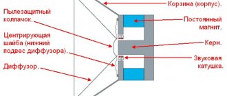
Speaker device
Any modern speaker includes a frame [1], which is also called a basket or even a spider. All other parts of the structure are supported on it.
A magnetic system is attached to the back of the basket, which consists of a ring magnet [2] and a magnetic core [3] - together they form an annular gap. This magnetic gap, the annular gap between two magnets, must be kept as small as possible to create the strongest possible magnetic field.
In the gap there is a so-called voice (sound) coil [4], which can perform reciprocating movements under the influence of a magnetic field, since an alternating current flows through it, corresponding in shape to the reproduced sound vibrations. It typically consists of wire coated with an insulating varnish and wound around a thin-walled cylinder called the voice coil frame [5].
It is attached to a diffuser [6] - a thin-walled structural element, which, when oscillating, actually reproduces sound. For this purpose, the diffuser must be able to move. For this purpose, so-called suspensions are installed [7, 8]: upper (outer) and lower. These are washers made of thin and flexible material with concentric bulges. Thanks to this shape, the suspensions allow the diffuser to move along the axis of symmetry of the entire structure back and forth.
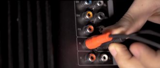
He does this because he is pushed by a voice coil, which is subject to an electromagnetic force proportional to the strength of the alternating current that is supplied to the coil through flexible torque-free conductors [9]. On the other side, these wires end with terminals [10], to which the speaker cable coming from the amplifier is connected.
The picture is completed by a dustproof cap [11], which is attached to the diffuser at the front and, as the name implies, protects the magnetic gap from the penetration of dust particles into it.
The variety of speakers is enormous. They differ in power, operating range of reproduced frequencies, scope of application and many other parameters. Naturally, the technologies and materials used in the production of each part depend on this. We will consider them separately.
Re: Connecting a subwoofer
Wires should be copper, stranded. This is a very dangerous limit, since with such resistance the damping coefficient is greatly reduced and distortion increases. It's a completely different matter if the subwoofer has two voice coils or two or more of them. So you can connect a subwoofer to a two or four channel amplifier, using 2 channels for acoustics, and the remaining 2 for the subwoofer. Most of the difficulties are caused by connection diagrams with two dual-coil subwoofers.
Each speaker is connected to a separate channel, while the subwoofer is installed as a bridge. To purchase the required set of wires, simply contact any store that sells sound systems for cars and tell them the model of your car and radio. Active subwoofer connection diagram. Inaccuracies when connecting the subwoofer to the standard radio and setting up the system cause resonance in the car and rattling of individual elements of the plastic trim.
Connecting to a subwoofer via a terminal block Connecting to a subwoofer directly Connecting a subwoofer with a bridge In the case of using a multi-channel amplifier, the sub can be connected to two channels simultaneously, using the minus of one and the plus of the other, this connection is called a bridge, with this method the power output by the amplifier significantly increases the specific numbers, see characteristics. General diagram Connection cost The average cost of connecting a subwoofer is 15 thousand. The first is needed to increase the power of the amplifier with a general calculation for a low load. How many ohms should I connect the subwoofer to?
Diffuser
Initially, the diffuser was made of cellulose - paper or cardboard. The dust cap (if provided) was also made from the same material. Cellulose diffusers are still very often used today. The paper is good for its combination of lightness and rigidity. Moisture resistance, strength and durability are added to it by impregnation with synthetic materials.
In this sense, plastic is good, but a purely plastic non-composite diffuser has a number of disadvantages. To correct them, composite materials with a variety of components are used: from wood or glass fibers to Kevlar or even graphene. Metal diffusers have increased rigidity. Most often they are made from aluminum alloys.
Beryllium has some of the best parameters, but due to the increased cost of the material and its processing technologies, this option is quite expensive. In so-called dome tweeters, impregnated fabric is most often used, sometimes reinforcing a layer of the most rigid composite, with a hard filler, even diamond powder.
The most important requirements for a diffuser are a minimum of self-resonances and maximum rigidity, at which the “piston” mode of movement of the diffuser over its entire area becomes possible. These parameters must be combined with the most important requirements for the weight of the moving speaker system - it must be minimal. Thus, a high-quality diffuser is always a compromise of mutually conflicting conditions.
Subwoofer coil repair
When repairing a subwoofer coil, the main thing is to carefully remove the diffuser and centering washer and not damage them. First, the speaker is removed from the speaker system. Then you need to unsolder the flexible conductors going from the coil to the contacts on the metal speaker basket. This must be done carefully so as not to damage the thin metal winding on a flexible thread base. The next important process is peeling off the diffuser. First you need to remove the center cap. A layer of solvent must be applied around its perimeter. This can be done using a syringe. It is convenient for them to gradually add the solvent composition until the cap comes off.
The diffuser is removed in the same way. Since it has a large diameter, it must be peeled off sequentially. First, a small area is impregnated with the solvent. After the glue has softened, part of the diffuser can be separated from the basket and a thin plate can be placed under this place. In this way, the entire diffuser is separated. Next, the centering washer is carefully and consistently separated. Acetone or compositions “646” or “647” can be used as a solvent.
Speaker suspension
The inner (closest to the magnet) speaker suspension is also called a centering washer. Most often, this part is molded on a heated press from lightweight, tensile fabric with elastic synthetic impregnation - firmly and movably. Some high-power woofers use two centering washers, one behind the other.
With external suspension everything is a little more complicated. Initially, it was made in the form of concentric waves (corrugations) along the outer edge of a paper diffuser. This is what they do now in some cases, adding synthetic impregnation to the corrugation zone. For large vibration amplitudes, the external suspension is made of rubber, most often it is artificial butadiene rubber. The cross-section of the rubber suspension, in most cases, is a convex arc. There are options for “multi-wave” rubber suspensions, or the use of other profiles, including variable angles.
Both suspensions must ensure a strictly plane-parallel reciprocating movement of the entire moving speaker system with minimal deviations to the side from its axis.
Voice coil
This coil, operating in the magnetic gap of the speaker, is wound on a frame - a cylinder, which is often made of thick paper. Heat-resistant plastic is also used for the frame: Kapton, textolite, or other composite materials. For greater density and temperature stability (under heavy load, i.e. loudness, the coil heats up), aluminum-based alloys and even titanium are used.
The wire used to wind the voice coil is most often copper. Aluminum wire is lighter, and this is a plus in this case, but it has its drawbacks (higher electrical resistance with lower temperature stability) and is used less often. There is an option with bimetallic aluminum wire coated with copper, which improves conductivity.
For a denser arrangement of turns, the wire is sometimes made rectangular or hexagonal in cross-section. To obtain several options for coil resistance when connecting its parts in parallel or in series or using separate amplifiers, the voice coil, most often in low-frequency speakers, can be divided into separate sections wound on a common frame.
To better cool the voice coil, the magnetic gap in some tweeters is filled with a special liquid filled with fine magnetic powder. This increases system efficiency and improves heat dissipation.
Which amplifiers can be connected to which resistance?
By lowering the resistance, we force the amplifier to deliver more power. For example, when connecting a speaker into 4 Ohms, the amplifier will output 500 W, and if the same speaker is reconnected to 1 Ohm, the power will be 1000 W.
The disadvantages of a low-impedance connection include:
- Increased load on the vehicle's on-board network.
- Increases amplifier distortion.
Simply put, we sacrifice sound quality in favor of volume. But not all amplifiers can be connected to a low-impedance load. As a rule, the manufacturer indicates in the instructions at what resistance the amplifier will operate stably without going into protection or breaking down.
The first thing we will pay attention to is the amplifier classes: AB and D.
- AB class amplifiers have a very low efficiency, that is, of the 100% of the power supplied to them, only 50-60% is converted into sound, the rest turns into heat. As a rule, manufacturers recommend using such amplifiers in 4 or 2 ohms. If such an amplifier is connected to 1 or 0.5 Ohm, it will get very hot. If there is protection, it will turn off itself. If it is not there, it will simply burn out.
- D-class amplifiers have an efficiency of more than 80%, as a result of which they heat up little. Such amplifiers are not afraid of low-impedance loads. The manufacturer recommends connecting them up to 1 ohm. But many people connect such amplifiers to 0.5 Ohm - here everything depends on the power supply and reliability of the amplifier.
In addition, amplifiers may differ in the number of channels. Using a two- or four-channel amplifier to connect a subwoofer, you will connect it with a bridge connection. In this mode, the device is already operating at its maximum load. If your bridged amplifier is class AB, then it can only be used into a 4 ohm load. When connected to a lower load, even 2 Ohms, it will get very hot and, possibly, go into protection, or simply burn out.
If the amplifier you want to connect is Class D, it is likely more suitable for low impedance loads and can be driven into 2 ohms. But first, you should still check in the instructions whether the manufacturer allows this.
Warning! You can connect the amplifier to a lower resistance (lower than indicated in the instructions) only if the following conditions are met: good power supply and not a maximum load. But remember that in this case the chance of equipment failure increases significantly. If something goes wrong, your warranty will be denied because you are using the device contrary to the recommendations provided by the manufacturer.
Magnetic system
The efficiency of a speaker's magnetic system is determined primarily by the material of the magnet. The most common is ferrite. In the middle of the last century, magnets made of the AlNiCo (iron-aluminum-nickel-cobalt) alloy were common; in some cases, this option is still used. In recent historical periods, neodymium magnets have become increasingly widespread, creating a much stronger magnetic field. The problem here was obtaining a neodymium workpiece of the required size: neodymium is a difficult material to process. In addition, the cost of neodymium magnets has been rising recently.
AudioKiller's site
I have long been surprised that speaker filter coils are made short and of large diameter. This is technologically advanced, but short coils of large diameter are much more sensitive to interference than long coils of small diameter. Here's an example of well-made coils in quality speakers:
And the opposite example of large-diameter coils (in all these cases the coil is not optimal in terms of active resistance, but if in the first case there is an excuse - better noise immunity, then in the second there are no excuses):
Moreover, the coils in the right photo (the worst) work as receivers for everything in the world and are located in the worst way. The most piquant thing is that this is a product of a Russian audiophile company, while the incorrect design and arrangement of the coils are compensated for by arrows on the wires.
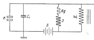
Figure 1 shows the interference magnetic field line (B). If the field passes through the coil (Fig. 1a), then an emf is induced in it. If the power line does not pass through the coil (Fig. 1b), then it does not affect the coil. In the case of a short coil, the interference affects all turns (Fig. 1c), but if the coil is long (Fig. 1 d), then the field affects only a small part of the turns, and this effect is less, the smaller the diameter of the coil.
But this was not a good enough reason to write about it. Moreover, the transmission of interference through the air at audio frequencies is quite weak.
Not long ago I needed to listen to the sound of the HF speakers. I assembled an LC filter, connected a speaker to the crocodile clips, and fed a signal from a computer amplifier (Fig. 2). To prevent the speakers from interfering, I removed one wire from their terminals.
I connected one speaker and listened. I disconnected it, took the second one, started connecting it... I leaned over the circuit and suddenly heard the speaker playing!!! Although very, very quiet. Moreover, both of its dynamics: both high and low frequencies! My first thought was that probably the disconnected wire lightly touches the self-tapping screw of the terminal, which in turn touches the crossover parts somewhere inside the speaker, and so the signal passes through. I checked: nothing like that. I also disconnected the second wire from the column. The sound remains!
The reason was this: the magnetic field created by the coil of my “desktop” filter induced a signal into the speaker that was sufficient for it to sound very quiet. By changing the position of the coil, I also changed the volume of the speaker.
But what exactly in the column is affected by the magnetic field of the coil? The magnetic field directly affects the speakers very little - when you bring the coil directly to the speaker, and the speaker directly to your ear, the sound is barely audible. Moreover, regardless of whether the speaker is shielded or not. This means that the pickup goes to the crossover coils (there are two of them in this column - on the HF and on the LF).
To test this hypothesis, I took two coils (from an old crossover, so they don’t look very nice, but they work great!) with an inductance of approximately 500 μH (Fig. 3).
Rice. 3. Coils for experiment.
I connected one of them through a 6 Ohm resistor to the same computer amplifier, and the second coil to a speaker (Fig. 4).
Rice. 4. Sound reproduction through the connection between the coils.
Result: when the amplifier was running at full power and the distance between the coils was 1 cm (matchbox), the speaker played quite loudly - 64 dB at a distance of 0.5 meters! I turn up the volume when I want to hear the sounds of Windows and programs (for example, some games), but so that they do not bother me.
Of course, this position of the coils is the most suboptimal, but nevertheless, it turns out that the mutual influence of the coils should not be immediately discarded. Let's check how the coils influence each other. Douglas Self did something similar, but he examined coils connected at the output of an amplifier, and they are a trifle compared to crossover coils. In addition, Self examined the coils at idle, but in reality they are connected to speakers, which causes a decrease in the induced voltage. In addition, I tried to generalize this whole matter so that I could evaluate the leads in any situations.
I passed a current of 1 ampere through one coil at a frequency of 10 kHz. And he positioned the second one in a certain way relative to the first one and measured the EMF induced in it (all quantities are effective values). The measurements were carried out both at idle and under a load of 8 ohms (the load was connected in parallel to the receiver coil). The graphs show both the absolute EMF induced in the receiver coil and the relative one in dB - relative to the voltage of 8 Volts required to produce a current of 1 Ampere.
So (the distance was measured directly between the windings of the coils), this arrangement is the worst:
The second option is better:
Another option is approximately the same (but here the geometry of the coils affects the result much more strongly than in the previous case):
This arrangement is even a little better:
The best arrangement is symmetrical. Ideally, there should be no interference at all (the interference on both halves of the coil are equal and opposite, so they are subtracted to zero)! But in reality, absolute symmetry of the coils cannot be obtained. Moreover, a slight shift of the coil to the side sharply breaks this very symmetry, so I had to make guides and move the coil along them - with the slightest shift to the side, the voltage in the receiver coil increased sharply.
In principle, if the coils are asymmetrical, then they can achieve almost absolute mutual non-influence by arranging them also slightly asymmetrically. Those. if you do a little magic. But there the influence of individual wires going to the coils is already beginning to affect.
In all of these graphs, the lines showing amplitude in dB should be straight. Their deviation from the straight line is an experimental error; it is mainly caused by some displacement of the coils from a given relative position and the inaccuracy of setting (or measuring) the distance X.
Now let's repeat experiment No. 1 (Fig. 5), but at a frequency of 1 kHz:
The results are predictable. Firstly, the amplitude at xx decreased in proportion to the frequency, that is, by an order of magnitude (taking into account the error). Secondly, the difference between the voltage at idle and under load has also decreased. Let me explain this second fact. A system of two coils forms a transformer (with an air core). The complete T-shaped equivalent circuit of the transformer is not of interest to us now, but in a simplified (and most important) way it turns out this:
Here M is the mutual inductance of the coils. From the equivalent circuit of the transformer, only XL connections remain (since the active resistance of the coils is very small, and we don’t need a transverse branch at all). Lconnection = const at a constant mutual position, and its inductive reactance is directly proportional to the frequency. At high frequencies, this resistance is greater, the voltage drop across it is greater when current flows, and the voltage drop under load is greater.
So far, physics is on our side: at low frequencies the induced EMF is less, at high EMF there is more, but the voltage drop under load is also greater - in any case, loaded coils have a lower induced voltage.
The parameters of the equivalent circuit can be calculated using the formulas:
Here f is the frequency, I is the current, M is the mutual inductance of the coils. All values are in Volts, Amperes, Henry, Hertz. But it is not possible to theoretically calculate the mutual inductance. But you can measure it: pass alternating current through one coil, and measure the no-load voltage in the other, and from formula (1) Fig. 12.
Less accurately (but with sufficient accuracy) it is possible to determine the mutual inductance M from my experiments. To do this, I needed to abandon the inductance of my coils and determine the inductive coupling coefficient K between them. Here are the graphs corresponding to the relative positions shown in Figures 5-9:
To determine the mutual inductance M in an arbitrary case, you need to multiply the coupling coefficient K, taken from the graph, by the root of the product of the inductances of both coils. Here is the formula for determining M:
Here is an example of a calculation for the 1st position (Fig. 5), a current of 1 Ampere, a distance between the coils of 1 cm and the inductance of each L1=L2=500 μH:
As you can see, the Uninduced coincides with the measured EMF at idle. At a frequency of 10 kHz, Lcoupling has a resistance of about 60 Ohms, so the voltage drop under load is large.
To take into account the shape of the coil (let's remember where it all started: the coil can be thin and long, or short with a large diameter), when calculating the mutual inductance, you can use an empirical correction factor (very, very rough) equal to the square root of the ratio of the diameter of the coil to its length (in identical units, for example, in centimeters):
In conclusion, I would like to note that the mutual influence of the coils is still very insignificant, and if you do not make gross mistakes, then it will not bring any harm.
16.02.2009
Total Page Visits: 1878 — Today Page Visits: 1