Design
The main purpose of inductors GOST 20718-75 is the accumulation of electrical energy within a magnetic field for acoustics, transformers, etc. They are used for the development and construction of various selective circuits and electrical devices. Their functionality, size and area of use depend on the design (material, number of turns), the presence of a frame. The devices are manufactured in factories, but you can make them yourself. Homemade elements are somewhat inferior in reliability to professional ones, but are several times cheaper.
Photo - diagram
The frame of the inductor is made of dielectric material. An insulated conductor is wound around it, which can be either single-core or multi-core. Depending on the type of winding, they are:
- Spiral (on a ferrite ring);
- Screw;
- Screw-spiral or combined.
A notable feature of an inductor for electrical circuits is that it can be wound either in several layers or unified, i.e., with scraps. If a thick conductor is used, then the element can be wound without a frame, if thin, then only on a frame. These inductor frames come in different cross-sections: square, round, rectangular. The resulting winding can be inserted into a special housing of any electrical device or used openly.
Photo - design of a homemade element
Cores are used to increase inductance. Depending on the purpose of the element, the rod material used varies:
- With ferromagnetic and air cores they are used at high current frequencies;
- Steel ones are used in low voltage environments.
At the same time, in electrical engineering, classical inductive coils without a core are actively used, which you can make with your own hands by winding them on a non-magnetic circuit. Such devices have some advantages over “core” ones. They have great impedance linearity. But, in the toroidal model, winding on a non-magnetic frame contributes to the appearance of parasitic capacitance.
Based on the principle of operation, there are the following types:
- Contour. They are mainly used in radio engineering to create oscillatory circuits on boards and work together with capacitors. The connection uses a serial connection. This is a modern version of the flat Tesla coil;
- Variometers. These are high-frequency tunable coils, the inductance of which can be controlled, if necessary, using additional devices. They represent a connection of two separate coils, one of which is movable and the other is not;
- Twin and tuning chokes. The main characteristics of these coils: low resistance to direct current and high resistance to alternating current. Chokes are made of several coils connected by windings. They are often used as a filter for various radio devices, installed to control interference in antennas, etc.;
- Communication transformers. Their design feature is that two or more coils are installed on one rod. They are used in transformers to provide a specific connection between the individual components of a device.
The marking of inductors is determined by the number of turns and the color of the housing.
Photo - marking
Analysis and preparation
Having looked at several diagrams of short-wave regenerative radio receivers, where a communication coil is also used, I came to the conclusion that for the experiment it would be enough to make a new loop inductor.
The 2K2M radio tube can operate at frequencies up to 25 MHz, so you can safely leave it without changing it to a higher frequency one.
What was a little confusing was the capacitance of the circuit CPE (variable capacitor), it lies in the range of 20-400 pF, which for the HF range is a little too much for both the minimum and maximum values. There were no plans to change the KPI, since everything already fits well on the chassis; the only idea was to try to slightly narrow its capacity by connecting a capacitor of some capacity in series.
The total capacitance of two series-connected capacitors can be calculated using the formula:
C total = (C1*C2) / (C1+C2)
When connecting a 50pF capacitor in series to the KPI (20-400pF), the total capacitance with adjustment will be 14-44pF. Not a very good value, although you can try.
Now we need to calculate the inductor so that we can receive radio stations in the HF range. On one forum I found a post where a person made a regenerator and used the following data for a HF coil (40-80m):
- Frame diameter - 45mm;
- The contour coil contains 12 turns of enameled wire with a diameter of 0.8 mm;
- The communication coil contains 3 turns of enameled wire with a diameter of 0.5 mm.
Trust but check! - let's not be lazy and calculate what we can achieve from a coil with such parameters.
Operating principle
The operation scheme of active inductors is based on the fact that each individual turn of the winding intersects with magnetic lines of force. This electrical element is necessary in order to extract electrical energy from a power source and convert it to store it in the form of an electric field. Accordingly, if the circuit current increases, then the magnetic field expands, but if it decreases, the field will invariably contract. These parameters also depend on frequency and voltage, but in general, the effect remains unchanged. Turning on the element produces a phase shift in current and voltage.
Photo - principle of operation
In addition, inductive (frame and frameless) coils have the property of self-induction, its calculation is made based on the data of the nominal network. In multilayer and single-layer windings, a voltage is created that is opposite to the voltage of the electric current. This is called EMF; the determination of electromotive magnetic force depends on inductance values. It can be calculated using Ohm's law. It is worth noting that regardless of the network voltage, the resistance in the inductor does not change.
Photo - connection of individual terminals of elements
The connection between inductance and the concept (change) of EMF can be found using the formula εc = - dФ/dt = - L*dI/dt, where ε is the value of self-induction EMF. And if the rate of change of electrical energy is equal to dI/dt = 1 A/c, then L = εc.
Video: calculating an inductor
Calculation of the inductance of a single-layer coil
Let's calculate the inductance of a single-layer loop coil using the formulas with the winding parameters given above. For clarity, I drew a picture:
Rice. 1. Inductor, parameters.
Formula for calculating coil inductance:
L = D*D*n*n / (45*D + 100*l), where:
- L—coil inductance, μH;
- D—coil diameter, cm;
- n is the number of coil turns;
- l is the length of the coil winding, cm.
L = 4.5*4.5*12*12 / (45*4.5 + 100*1.1) = 2916 / (202.5 + 110) = 9.3 μH(μH) =0.0000093 Hn = 9.3 * 10−6 Hn.
The inductance of the coil, which contains 12 turns of wire (approximately 1.1 cm in length with 0.8 mm wire) and is wound on a frame with a diameter of 45 mm, is 9.3 μH (μH). It's simple!
HF bands table
Short waves, reflected from the surface of the earth, can spread over fairly large distances. How well we can receive waves of different lengths depends on many factors, one of the most pronounced is the time of day: day or night.
During the day, shorter waves travel well, and at night, longer waves travel well.
Below is a table of HF broadcast bands with a note depending on the time of day:
- 11 meters, 25.600 - 26.100 MHz (daytime);
- 13 meters, 21.450 - 21.850 MHz (daytime);
- 15 meters, 18.900 - 19.020 MHz (daytime);
- 16 meters, 17.480 - 17.900 MHz (daytime);
- 19 meters, 15.100 - 15.900 MHz (daytime);
- 21 meters, 13.500 - 13.870 MHz;
- 25 meters 11.600 - 12.100 MHz;
- 31 meters, 9.400 - 9.990 MHz;
- 41 meters, 7.200 - 7.600 MHz;
- 49 meters, 5.730 - 6.295 MHz;
- 60 meters, 4.750 - 5.060 MHz (night);
- 75 meters, 3.900 - 4.000 MHz (night);
- 90 meters, 3.200 - 3.400 MHz (night);
- 120 meters, 2.300 - 2.495 MHz (night).
Based on my calculations made above, I will be able to cover ranges of approximately 41 - 25 meters with the radio.
Installing an HF coil in a radio receiver
Now the HF coil is ready to be installed in the radio receiver. You should try to use the shortest possible leads from the windings when connecting them to the components of the radio receiver.
Rice. 10. The HF band coil is installed in the radio receiver. (click - enlarge).
Rice. 11. radio receiver with an installed HF coil, rear view. (click - enlarge).
Rice. 12. Ready HF receiver and old coil for the MF-LW ranges.
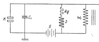
Calculation of the frequency of the oscillatory circuit
Knowing the inductance of the coil and the capacitance of the capacitor in our oscillatory circuit, we can calculate its resonant frequency.
Rice. 2. Diagram of an oscillatory circuit.
We will calculate the frequency of the oscillatory circuit using the formula:
ƒ = 1 / (2 * π * √(LC)), where:
- ƒ — resonant frequency of the circuit, Hz;
- π—pi number, 3.1415;
- L—coil inductance, H;
- C is the capacitance of the capacitor, F.
Let's calculate the frequency of the oscillatory circuit by taking the lower capacitance of the KPE capacitor that I have: C = 20 pF = 0.00000000002 F = 20 * 10−12F.
ƒ1 = 1 / (2 * 3.14 * √ (0.00000000002*0.0000093)) = 11675725.7 Hz = 11.67 MHz.
Now the same thing, but we take the upper limit of the KPI capacity, let’s take more than half: C = 300pF = 0.0000000003 F = 300 * 10−12F.
ƒ2 = 1 / (2 * 3.14 * √ (0.0000000003*0.0000093)) = 3014659.4 Hz = 3.01 MHz.
And, using an inductor with the above parameters and my KPI, I can cover the range from approximately 3 to 11 MHz.
What parameters does the coil have?
Its design depends on where the inductive element will be used and at what frequency it will operate. There are general parameters:
- L – inductance;
- R sweat – loss resistance;
- Q – quality factor;
- its resonance and parasitic capacitance;
- coefficients TKI and TKD.
What does inductance depend on
? Inductance (self-inductance coefficient) L is the main electrical characteristic of the element, which shows the amount of energy accumulated by the inductor when current flows. The greater the inductance, the higher the energy in the coil. Unit of measurement L – 1 Hn.
When current and magnetic field interact in the winding, harmful phenomena occur. They contribute to the occurrence of losses, which are denoted by R sweat. The loss formula looks like:
R sweat = rω + rd + rs + re.
The terms of the formula are losses:
- rω – in wires;
- rd – in dielectric;
- rs – in the core;
- re – for eddy currents.
As a result of such losses, the impedance of an inductive two-terminal network cannot be called entirely reactive.
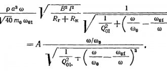
The quality factor of a two-terminal network is determined by the formula:
Q = ω*L/R sweat,
where ω*L = 2π*L – reactance.
When winding the turns of an element, unnecessary capacity appears between them. Because of this, the choke turns into an oscillatory circuit with its own resonance.
TCI is an indicator describing the dependence of L on Т0С.
TKD is an indicator that describes the dependence of the quality factor on T0C.
Information. Changes in the main parameters of an inductive two-terminal network depend on the TCI, TKD coefficients, as well as on time and humidity.
Making an inductor
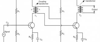
All data is available, you can start manufacturing the inductor. To illustrate the connection of the coils, I will place here part of the circuit from my radio receiver.
Rice. 3. Diagram for connecting inductors in a radio receiver (the beginnings of winding are indicated by a dot).
If you look at the diagram, for one range you can wind only two coils on the frame: the contour coil will replace L1 and L2, and the communication coil will replace L3 and L4, while switch S1 can be eliminated.
I nevertheless decided to make 4 coils as in the diagram for the sake of experiment, I wonder how such a solution will behave in the HF range, besides, it is possible that it will be possible to capture an even lower frequency range in addition to the main one.
ATTENTION: it is necessary to observe the beginnings and ends of the winding when installing the coil, as well as the winding direction of each of the windings. Read in detail in the article: Homemade battery radio receiver using a 2K2M lamp.
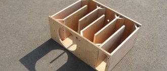
The first step is to make a frame on which we will wind the wire. Under the frame, you can use a piece of polyethylene or plastic pipe or another cylinder of the required diameter.
I will need a frame with a diameter of 45mm, since I found a pipe with a slightly smaller diameter of 40mm in junk and in order not to spoil it, I decided to glue a paper frame around it.
Rice. 4. The frame for the coil is a piece of pipe.
For gluing I used A4 sheets - the paper is quite thick and well suited for such purposes. First, we wrap 1-2 sheets of paper onto the frame without covering it with glue, this is necessary so that we can then remove the pipe.
Rice. 5. Several layers of paper glued together for the frame of the future reel.
Now we spread glue on each sheet of paper and wrap the frame in it. It is advisable to stick 5 or more sheets of paper - this will help to achieve sufficient strength of the frame when it dries. Drying is enough for 12 hours if glued with PVA glue.
After the frame had dried, it turned out that it was so tight on the pipe that it was no longer possible to remove it - I had to cut the frame lengthwise and, after removing it, glue the cut. The frame is ready and it is strong enough to hang a thick wire on it.
Rice. 6. The paper frame for the inductor is ready.
For winding I used a copper conductor with a diameter of 0.8mm and 0.5mm - a loop and a communication coil, respectively.
Rice. 7. A homemade inductor for the HF range is ready!
Rice. 8. Homemade HF coil - view from the terminals.
For convenience, I marked the starting points for winding the coils - this will help you avoid getting confused when connecting it to the radio. The conductors were fastened by making holes in the frame using a needle.
Rice. 9. We fasten the turns of the windings with wax.
In order for the turns of the coil windings to stay securely together, you can glue them together with glue or simply drop a few drops of wax.
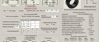
Calculation of chokes using MLT resistors and ferrite cores
Homemade chokes based on MLT resistors and 2.8mm ferrite cores. Making a choke by winding a conductor on an MLT resistor is an inexpensive and simple way to obtain a small-sized electronic component, which can often be found in circuits of radio transmitters, radio receivers, transceivers, televisions and other electronic equipment.
Rice. 1. Homemade chokes based on MLT resistors.
Below we will present a simple calculator form for calculating the inductance and the number of turns of wire for chokes that are made by winding on resistors MLT-0.125, MLT-0.25, MLT-1, MLT-2, thus we get a choke without a core, with a convenient frame serves as the housing of a high-resistance resistor.
Working with a receiver in the HF range
The receiver is ready for use, you can start experimenting. The tests were carried out in the evening and at night. First, a long antenna was connected - a piece of rough copper wire about 10 meters long.
With such an antenna, I was able to pick up several stations, and the feedback adjustment knob did not affect the operation of the radio in any way; this seemed strange to me - perhaps I mixed up the beginnings and ends when connecting the feedback windings.
Connecting the ground also did not improve the performance of the radio. I decided to try a copper pin with a diameter of 1-1.2 mm and a length of about 1-1.5 m as an antenna.
After turning on the radio, the result was not long in coming - we managed to catch several stations, and the regeneration knob now worked perfectly and it was possible to catch and amplify fairly weak signals from broadcast stations.
It was possible to hear Radio Liberty, broadcasts from other countries, coded signals and other stations on HF. The largest accumulation of stations was observed at the threshold limit of the KPI adjustment (C = 20 pF), most likely if you reduce this threshold to 10 pF, you will be able to catch even more stations, or you need to recalculate the coil and then rewind it.
The receiver has become less resistant to adjustments under the influence of hands and touches of different parts of the circuit. Sometimes you can even play around with the receiver antenna as with the antenna of a theremin (musical instrument).