Laboratory low frequency generator
A low-frequency sine wave generator is a very important device in the laboratory of any radio amateur. Perhaps everyone already has one. But I still want to introduce the magazine’s readers to my generator.
The generator is designed as an independent device, powered from the mains. But his scale is only approximate - drawn with a permanent marker directly on the body of the device around the variable resistor with which the frequency is regulated.
To accurately set the frequency, another independent device is used - a frequency meter based on the ARDUINO UNO board, by the way, made in the same case. As for the case, back in the 2000s, our company once updated its computer equipment and then four mechanical printer switches “Data transfer switch” (that’s what it says on them) went to waste. They are ancient, dating back to the days of Windows 3.11.
In metal cases measuring 150x60x10 cm. In general, a very convenient size for homemade devices. Then I got four of them. One now has a frequency meter on Arduino, another has an adjustable power supply, the third has an HF generator, and the fourth has this same LF generator. The circuit of the LF generator is shown in the figure given here. The circuit is based on operational amplifier A1. This is a sinusoidal signal generator, frequency tunable by a dual variable resistor R17 in four frequency generation ranges 10-100 kHz, 1-10 kHz, 100-1000 Hz, 10-100 Hz.
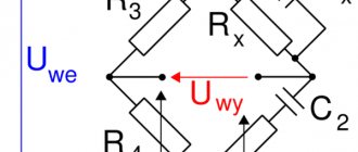
The circuit is built with a Wynne bridge in the positive feedback circuit of the operational amplifier. A dual variable resistor regulates the R-component of this bridge. The C-component consists of eight capacitors C1-C8, switched by a roller switch S1 when changing the generation range. And stabilization of the op-amp transmission coefficient is carried out through the amplifier's OOS circuit using back-to-back diodes VD1, VD2 and resistor R1. By selecting the resistance of this resistor when setting up the generator, the correct sinusoid is set at the generator output (with minimal distortion).
From the output of the operational amplifier, the generated signal is supplied to two outputs - connectors X1 and X2. The main output from which the signal is supplied to the circuit under study is connector X1. The magnitude of the low frequency voltage on it can be adjusted with variable resistor R6. And, if necessary, add a resistor divider. But I don’t have a divider; when I need to get a small signal, I solder a divider on the spot on two resistors with the division coefficient needed in this case.
The second output to connector X2 is used to control the frequency using an external independent frequency meter. This output is not amplitude adjustable. The operational amplifier is powered by a bipolar voltage of about 12V. To obtain this voltage, a low-power power transformer T1, presumably made in China, is used. When the primary winding is connected to a 220V network, the secondary winding produces an alternating voltage of 9V at idle.
There is one winding, and to obtain two voltages that are identical in magnitude, but different in value, a rectifier circuit is used on two diodes VD3 and VD4 and two capacitors C9 and SY. In fact, these are two different half-wave rectifiers that receive alternating voltage from one source - the secondary winding of transformer T1. Diode VD3 rectifies the positive half-wave, and diode VD4 rectifies the negative half-wave. Since the alternating voltage in the electrical network is sinusoidal and the half-waves are symmetrical, voltages equal in magnitude but opposite in polarity are released on capacitors C9 and SY.
It is this bipolar voltage that powers the operational amplifier. All capacitors must have a voltage of at least 16V. The operational amplifier K140UD608 can be replaced with almost any general purpose operational amplifier, for example, K140UD6, K140UD7, K140UD708, etc., including imported analogues. The installation was done without the use of a printed circuit board, even without a breadboard.
Although, at first there was an idea to assemble it on a breadboard. The necessary holes were drilled into the front panel of the above metal case and all the variable resistors, connectors, switch and power switch were installed. The transformer is screwed to the bottom of the housing. After installing the capacitors directly on the contacts of switch S1, it became clear that it would be convenient to assemble everything “in weight”, without any printed circuit boards or other boards.
Diagram, technical characteristics, operation of the GUK-1 generator.
a GUK-1 generator for repair .
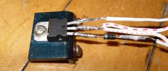
No matter what I thought later, I immediately replaced all the electrolytes. Oh miracle! Everything worked. The generator is from Soviet times, and the attitude of the communists towards radio amateurs was such X... that there is no desire to remember. This is where the generator would like to be better. Of course, the most important inconvenience is setting the frequency of the high-frequency generator. At least they installed some simple vernier, so I had to add an additional trimming capacitor with an air dielectric (Photo 1). To tell the truth, I chose the place for it very poorly; I should have moved it a little. I think you will take this into account.
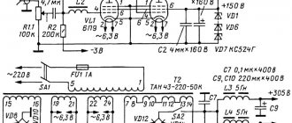
To install the handle, I had to lengthen the trimmer axis, a piece of copper wire with a diameter of 3mm. The capacitor is connected in parallel to the main control unit either directly or through a “stretching” capacitor, which further increases the smoothness of tuning of the RF generator. For the heap, I also replaced the output connectors - my relatives were already in tears. This completes the repair. I don’t know where the generator circuit came from, but it looks like everything matches. Perhaps it will be useful to you too. The circuit diagram of the universal combined generator - GUK-1 is shown in Figure 1. The device includes two generators, a low-frequency generator and a high-frequency generator.
TECHNICAL DATA
1. The frequency range of the HF generator from 150 kHz to 28 MHz is covered by five subranges with the following frequencies: • 1 subrange 150 - 340 kHz • II 340 - 800 kHz • III 800 - 1800 kHz • IV 4.0 - 10.2 MHz • V 10.2 - 28.0 MHz
2. HF installation error no more than ±5%. 3. The RF generator provides smooth adjustment of the output voltage from 0.05 mV to 0.1 V. 4. The generator provides the following types of work: a) continuous generation; b) internal amplitude modulation with sinusoidal voltage with a frequency of 1 kHz. 5. Modulation depth of at least 30%. 6. The output resistance of the RF generator is no more than 200 Ohms. 7. The low-frequency generator generates 5 fixed frequencies: 100 Hz, 500 Hz, 1 kHz, 5 kHz, 15 kHz. 8. Permissible frequency deviation of the LF generator is no more than ±10%. 9. The output resistance of the low-frequency generator is no more than 600 Ohms. 10. LF output voltage is smoothly adjustable from 0 to 0.5 V. 11. Self-heating time of the device is 10 minutes. 12. The device is powered by a 9 V Krona battery.
Function transistor generator
Transistor voltage stabilizer
Functional generators based on self-oscillation transistors are invented to produce methodically repeating pulse signals of a given shape. Their form is determined by the function (the name of the entire group of similar generators appeared as a result of this).
There are three main types of impulses:
- rectangular;
- triangular;
- sawtooth.
A multivibrator is often cited as an example of the simplest LF producer of rectangular signals. It has the simplest circuit for DIY assembly. Radio electronics engineers often begin with its implementation. The main feature is the absence of strict requirements for the ratings and shape of transistors. This occurs due to the fact that the duty cycle in a multivibrator is determined by the capacitances and resistances in the electrical circuit of transistors. The frequency on the multivibrator ranges from 1 Hz to several tens of kHz. It is impossible to organize high-frequency oscillations here.
Obtaining sawtooth and triangular signals occurs by adding an additional circuit to a standard circuit with rectangular pulses at the output. Depending on the characteristics of this additional chain, rectangular pulses are converted into triangular or sawtooth pulses.
Video
Coffee capsule Nescafe Dolce Gusto Cappuccino, 3 packs of 16 capsules
1305 ₽ More details
Coffee capsules Nescafe Dolce Gusto Cappuccino, 8 servings (16 capsules)
435 ₽ More details
Smart plugs
Picture on electrical diagrams
Blocking generator: operating principle
First, let's consider obtaining a sinusoidal type of signal. The most famous oscillator based on a transistor of this type is the Colpitts oscillator. This is a master oscillator with one inductance and two series-connected capacitors. It is used to generate the required frequencies. The remaining elements provide the required operating mode of the transistor at direct current.
Additional Information. Edwin Henry Colpitz was the head of innovation at Western Electric at the beginning of the last century. He was a pioneer in the development of signal amplifiers. For the first time he produced a radiotelephone that allowed conversations across the Atlantic.
The Hartley master oscillator is also widely known. It, like the Colpitts circuit, is quite simple to assemble, but requires a tapped inductance. In the Hartley circuit, one capacitor and two inductors connected in series produce generation. The circuit also contains an additional capacitance to obtain positive feedback.
Transistor generator circuits
The main area of application of the devices described above is medium and high frequencies. They are used to obtain carrier frequencies, as well as to generate low-power electrical oscillations. Receiving devices of household radio stations also use oscillation generators.
All of the listed applications do not tolerate unstable reception. To do this, another element is introduced into the circuit - a quartz resonator of self-oscillations. In this case, the accuracy of the high-frequency generator becomes almost standard. It reaches millionths of a percent. In receiving devices of radio receivers, quartz is used exclusively to stabilize reception.
As for low-frequency and sound generators, there is a very serious problem here. To increase the tuning accuracy, an increase in inductance is required. But an increase in inductance leads to an increase in the size of the coil, which greatly affects the dimensions of the receiver. Therefore, an alternative Colpitts oscillator circuit was developed - the Pierce low-frequency oscillator. There is no inductance in it, and in its place a quartz self-oscillation resonator is used. In addition, the quartz resonator allows you to cut off the upper limit of oscillations.
In such a circuit, the capacitance prevents the constant component of the base bias of the transistor from reaching the resonator. Signals up to 20-25 MHz, including audio, can be generated here.
The performance of all the devices considered depends on the resonant properties of the system consisting of capacitances and inductances. It follows that the frequency will be determined by the factory characteristics of the capacitors and coils.
Important! A transistor is an element made from a semiconductor. It has three outputs and is capable of controlling a large current at the output from a small input signal. The power of the elements varies. Used to amplify and switch electrical signals.
Additional Information. The presentation of the first transistor was held in 1947. Its derivative, the field-effect transistor, appeared in 1953. In 1956 The Nobel Prize in Physics was awarded for the invention of the bipolar transistor. By the 80s of the last century, vacuum tubes were completely forced out of radio electronics.
Blocking generator
Current stabilizer on a transistor
At its core, it is an amplifier assembled on the basis of transistors arranged in one cascade. The scope of application is narrow - a source of impressive, but transient in time (duration from thousandths to several tens of microseconds) pulse signals with large inductive positive feedback. The duty cycle is more than 10 and can reach several tens of thousands in relative values. There is a serious sharpness of the fronts, practically no different in shape from geometrically regular rectangles. They are used in the screens of cathode-ray devices (kinescope, oscilloscope).
Pulse generators based on field-effect transistors
The main difference between field-effect transistors is that the input resistance is comparable to the resistance of electronic tubes. Colpitts and Hartley circuits can also be assembled using field-effect transistors, only the coils and capacitors must be selected with the appropriate technical characteristics. Otherwise, field-effect transistor generators will not work.
The circuits that set the frequency are subject to the same laws. For the production of high-frequency pulses, a conventional device assembled using field-effect transistors is better suited. The field effect transistor does not bypass the inductance in the circuits, so the RF signal generators operate more stably.
Self-oscillating transistor devices
The transistor generator is divided into several types:
- according to the frequency range of the output signal;
- by type of signal generated;
- according to the action algorithm.
The frequency range is usually divided into the following groups:
- 30 Hz-300 kHz – low range, designated low;
- 300 kHz-3 MHz – medium range, designated midrange;
- 3-300 MHz – high range, designated HF;
- more than 300 MHz – ultra-high range, designated microwave.
This is how radio amateurs divide the ranges. For audio frequencies, they use the range 16 Hz-22 kHz and also divide it into low, medium and high groups. These frequencies are present in any household sound receiver.
The following division is based on the type of signal output:
- sinusoidal – a signal is issued in a sinusoidal manner;
- functional – the output signals have a specially specified shape, for example, rectangular or triangular;
- noise generator – a uniform frequency range is observed at the output; ranges may vary depending on consumer needs.
Transistor amplifiers differ in their operating algorithm:
- RC – main area of application – low range and audio frequencies;
- LC – main area of application – high frequencies;
- Blocking oscillator - used to produce pulse signals with high duty cycle.
Frequency division
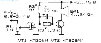
Simple DIY sound generator
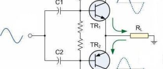
Let's consider the simplest example - the howler monkey. You only need four elements: a film capacitor, 2 bipolar transistors and a resistor for adjustment. The load will be an electromagnetic emitter. A simple 9V battery is enough to power the device. The operation of the circuit is simple: the resistor sets the bias to the base of the transistor. Feedback occurs through the capacitor. The tuning resistor changes the frequency. The load must have high resistance.
Sound generator circuit
With all the variety of types, sizes and designs of the considered elements, powerful transistors for ultra-high frequencies have not yet been invented. Therefore, generators based on self-oscillation transistors are used mainly for the low and high frequency ranges.
RF Generator PCB Drawing
The drawing in LAY format was kindly provided by Igor Rozhkov, for which I express my gratitude to him for myself and for those who will find this drawing useful.
The archive below contains Igor Rozhkov’s file for an industrial amateur radio generator with five HF bands - GUK-1. The board is presented in *.lay format and contains a modification of the circuit (sixth switch for the 1.8 - 4 MHz range), previously published in Radio magazine 1982, No. 5, p. 55 Download the printed circuit board drawing.