A selection of amplifier boards on microcircuits for assembling your own power amplifier
Do you want to assemble a power amplifier for home acoustics with good sound yourself, but don’t know which option to choose? First you need to try an amplifier board on microcircuits. It is inexpensive, and will have enough power for home speakers and low distortion. Consider Chinese solutions on popular audio amplifier chips.
But in any case, before the finished amplifier, in addition to the boards, you need:
- Power supply (mains transformer + rectifier with power capacitors) It plays an important role.
- Acoustic protection on the relay (if necessary, if not on the board)
- Soft start for a smooth start (if necessary, at high power)
- Volume adjustment (for example, the simplest one is with a dual variable resistor)
- Input selector (if you need to connect many devices)
- Case with cooling radiators or with good convection
Let's look at the options for amplifier boards on microcircuits on the AliExpress site from reliable sellers.
LM1875
Find out the price
The selection opens with a simple version of LM1875 from AIYIMA. The lot includes a kit for self-assembly.
Surprisingly high-quality sound with low distortion, and there is acoustic protection on the relay.
Option with low power (up to 30 W) and compact size 99x63 mm.
The board is powered by 12-22 V AC with a midpoint.
Short circuit and thermal protection. Good quality components.
TDA7294
Find out the price of Rectifier unit
A small board with simple wiring based on a pair of well-known TDA7294 microcircuits. Maximum power 70 W per channel into 4 ohms.
The board is small (106x55 mm), because it requires a power supply (rectifier + power supply capacitors) with a bipolar voltage of 35 V. A network transformer is required with secondary windings of 15-28 V.
In this lot you can choose from:
- PCB only without parts
- Assembled amplifier board
TDA7293 DC servo
Find out the price
Now a more sophisticated version on a pair of TDA7293. Maximum power up to 100 W. “DC servo” circuit design (zero level of direct voltage at the output is supported by the integrator) on OP07+NE5534. The board also provides acoustic protection on a UPC1237 chip and relay.
The board is large (150x135 mm), but this is understandable, there is a rectifier, capacitors and an integrator. A transformer for power supply is needed with a secondary winding of 12-28 V.
In this lot there is a choice:
- Assembled board with cooling radiator
- Assembled board without heatsink
- Assembly kit with radiator
- Assembly kit without radiator
LM3886
Find out the price
You can't ignore the famous LM3886 chip. High-quality, detailed sound. 68 W maximum power.
This board is small (118x71 mm), but it accommodates a pair of electrolytes with a capacity of 10,000 uF and acoustic protection on a UPC1237 with a relay. A transformer for power supply is needed with secondary windings of a maximum of 24-0-24 V.
High quality components. They promise the original LM3886TF (in a plastic case, no gasket required for installation on the radiator).
LM3886 DC Servo
Find out the price
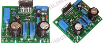
An advanced version of the board based on a pair of LM3886. She is also depicted in the title photo of the topic. A good option. Board size 155 x 80 mm. Circuit design DC Servo. Operators 5534 in cribs.
The board has everything included, including a rectifier and acoustic protection. A transformer is required with secondary windings of 15-28 V.
The lot includes a choice: an assembly kit/assembled board and an option with or without a radiator. If you take it without a radiator, the microcircuits can be mounted without spacers.
Lots of positive feedback.
LM4766
Find out the price
An option that is not well-known to everyone, unlike the popular previous microcircuits. LM4766 is a medium power chip that produces a maximum of 40 W per channel. One on the board. The sound is quite suitable for desktop systems. I made an amplifier on it, it sounded and measured well.
All-in-one board (112X68mm) with rectifier, capacitors and relay protection. Power supply is a transformer with a secondary winding of 15-22 V.
The lot contains a choice of either an assembly kit or an assembled and tested board.
STK401-110
Find out the price of STK433-260
The selection is completed by a variant with high output power and a hybrid chip. Yes, let's make some assumption. STK are hybrid microcircuits made on unpackaged transistors using thick-film technology in a fairly large package. Something between a transistor and a microcircuit amplifier.
STK401-110 is a really powerful option, handles up to 42 V power supply, and produces real 100+ W per channel at 4 Ohms. There is even a connector for a cooling fan.
Option STK433-260 - when you want a hybrid microcircuit, but you don’t need a lot of “stupidity” at the output. Here it is ideal for this, it has 2x50 W and the same high-quality board with a rectifier and protection.
I hope the selection of amplifier boards on chips for a DIY audio project was useful and you will choose an option to suit your taste (hearing) and budget.
Happy shopping! Don't forget to apply AliExpress coupons and discounts.
High power ULF
The uPC2005V chip is a two-channel/bridged ULF amplifier (20W at 14V).
The uPC2005V chip is a two-channel/bridged low-frequency amplifier. Maximum supply voltage = 18 V; Nominal gain = 50 dB; Output power per channel (Vcc = 14.4 V, Ru = 40m, THD = 10%) = 20 W; Current consumption in quiescent mode = 75 mA; Range…
0 2259 0
IC uPC1288V - stereo/bridge ULF (5-20W at 25V)
The uPC1288V chip is a two-channel/bridge low-frequency amplifier. Maximum supply voltage = 25 V; Nominal gain 48 dB; Current consumption in rest mode = 23 mA; Operating temperature range = -20…+75 C. Output power: at…
0 4940 0
IC uPC1280V - bridge bass amplifier (20W at 13V)
The uPC1280V chip is a low-frequency bridge amplifier. Nominal supply voltage = 13.2 V; Maximum output power (Vcc= 13.2 V, Rl = 40m, THD = 10%) = 20 W; Current consumption in quiescent mode = 90 mA; Operating temperature range = -30…+75°C. ...
0 2098 0
IC uPC1274V - bridge bass amplifier (20W at 13V)
The uPC1274V chip is a low-frequency bridge amplifier. Supply voltage: nominal = 13.2V, maximum = 18V; Maximum output power (Vcc = 13.2 V, Rl = 4 Ohm, THD = 10%) = 20W; Current consumption in quiescent mode = 90 mA; Operating temperature range …
0 2366 0
Chip TDA7375 - 2/4-channel automotive ULF (7-25W at 14.4V)
The TDA7375 chip is a two/four-channel low-frequency amplifier. Nominal supply voltage = 14.4 V; Maximum output power: per channel (Vcc = 14.4 V, RL = 4 Ohm, THD = 10%) = 7 W, bridged (Vcc = 14.4 V, Rl = 4 Ohm, THD = 10%) = 25 W; Built-in circuit...
1 7837 0
Chip TDA7365 - two-channel ULF (25W at 25V)
The TDA7365 chip is a two-channel low-frequency amplifier. Maximum supply voltage = +/-25 V; Maximum output power per channel (Vcc = 20 V, RL = 8 Ohm, THD = 10%) = 25 W; Built-in protection against thermal and current overloads. Microcircuit pinout......
1 6319 0
Chip TDA7250 - driver for powerful stereo ULF (10-45V)
The TDA7250 chip is a control circuit (driver) for a two-channel low-frequency amplifier. Supply voltage = ±10…±45 V; Blocking mode and standby mode; Automatic control of quiescent current and overcurrent protection of output transistors. Tsokolevka…
1 4678 0
IC uPC1230H2 - bridged ULF for cars (20W at 13.2V)
The uPC1230H2 chip is a low-frequency bridge amplifier. Supply voltage: nominal = 13.2 V, maximum = 18 V; Maximum output power (Vcc = 13.2 V, RL = 4 ohms, THD = 10%) = 20 W; Current consumption in quiescent mode = 90 mA; Operating temperature range =…
0 6257 0
Chip TDA7390, TDA7391 - automotive bridge ULF (25W at 14.4V)
The TDA7390, TDA7391 microcircuit is an automobile bridge ULF. Rated supply voltage = 14.4V; Maximum output power (Vcc = 14.4 V, Rl = 40m, THD = 10%) = 25 W; Differential inputs; Gain = 30 dB; Distortion detector; ...
0 4256 0
Chip TDA7241 - bridge bass amplifier (20W at 18V)
The TDA7241 chip is a low-frequency amplifier with a bridge output. Gain = 26 dB; Maximum supply voltage = 18V; Maximum amplitude of supply voltage surges (50 ms) = 40 V; Maximum output current = 3.5 A; Maximum power output...
0 3963 0
1
Circuitry and microcircuits for modern UMZCH class D
Increasing the efficiency of audio power amplifiers (AFPA) is one of the important tasks of the developer of wearable (mobile) and a number of other analog and digital devices. Often the best solution to this problem is the use of class D UMZCH. In recent years, many specialized class D UMZCH microcircuits have appeared with high efficiency (almost 100%) and a low nonlinear distortion coefficient (noticeably less than 10%). The article describes the basic principles of operation and circuit design of class D amplifiers based on UMZCH microcircuits from different companies.
For two decades, UMZCH circuitry has been developing in two mutually exclusive directions. Firstly, this is an improvement in the subjective quality of sound reproduction (usually due to a decrease in the efficiency of the amplifier), and secondly, an increase in the efficiency (efficiency) of the amplifier and a reduction in its size while maintaining high sound quality. The output stages of amplifiers of the first type use powerful field-effect transistors or radio tubes (Hi-End), operating in linear mode - class A or its modifications. The second direction is developing mainly in the sector of wearable and automotive sound-reproducing equipment. This is where class D amplifiers are widely used. In high-quality stationary sound reproduction equipment, class D has also begun to be used - most often in subwoofer amplifiers, where, due to the low bandwidth, very little distortion can be achieved.
Modern “classic” microcircuits UMZCH class D
The use of class D UMZCHs has been significantly expanded by the creation of microcircuits containing not only a driver, but also output switches based on MOS transistors. An example is the MP77xx series microcircuits from MPS (Monolithic Power Systems). In total, at the time of writing, there were five such microcircuits: MP7720, MP7722, MP7731, MP7781 and MP7782. The rated output power is indirectly indicated by the penultimate digit in the name of the microcircuit (see Table 1).
Table 1. Main parameters of UMZCH class D microcircuits from MPS
| Options | Microcircuits | ||||
| MP7720 | MP7722 | MP7731 | MP7781 | MP7782 | |
| Mono/stereo | Mono | Stereo | Mono | ||
| Rated power, W (Up = 24 V, load 4 Ohm) | 20 | 2 × 20 | 30 (Upit = 16 V) | 80 | 50 (6 ohm load) |
| Total nonlinear distortion (THD+N), % (at a frequency of 1 kHz at an output power of 1 W) | 0,1 | 0.06 (8 ohm load) 0.16 (4 ohm load) | 0,1 | 0,2 | 0,06 |
| Efficiency, % | 90 (at 20 W) | 93 (20 W) | 90 (5 W) | 95 (80 W) | 90 (50 W) |
| PWM conversion frequency, kHz | 600 | 600…800 | 600 | 400 | 400…600 |
| Output type | Half bridge | Bridge | |||
| Channel resistance of output MIS switches in saturation state, Ohm | 0,18 | 0,105 | 0,18 | ||
| Dynamic range, dB | 93 | 80 | 90 | ||
| Frame | SOIC8 or PDIP8 | TSSOP20F | SOIC24 | TSSOP20F | |
The supply voltage for all microcircuits is 7.5…24 V; effective input signal voltage is 1 V.
The exception is the MP7782 chip, which develops 50 W into a 6 Ohm load. The peak output power of all microcircuits in this series is twice the rated one. Table 1 also shows other important parameters of the MP77xx microcircuits. For example, let's take a closer look at the UMZCH on the MP7722 and MP7782 microcircuits.
Class D stereo UMZCH chip MP7722
The scope of application of this chip is DVD players, home stereo systems, multimedia PCs, TVs - both conventional and flat panel (LCD and PDP). The MP7722 chip is available in a surface-mount package TSSOP20F, the dimensions of which, including pins, are approximately 6.5 × 6.5 mm with a height of 1.2 mm. The UMZCH on this chip has a rated power of 20 W with a load resistance of 4 Ohms and a supply voltage of 24 V. The reproducible frequency range is 20 Hz...20 kHz. The amplifier has an efficiency of 90% with a nonlinear distortion coefficient of no more than 0.1% for the entire frequency range (with an output power of 1 W). Each channel of the microcircuit has two output switches built on MOS transistors, which are connected in series via the power supply (half-bridge). The schematic diagram of a class D stereo UMZCH on the MP7722 chip is shown in Figure 1, and the purpose of the parts is summarized in Table 2.
| Rice. 1. Schematic diagram of a class D stereo UMZCH on the MP7722 chip |
Table 2. Purpose of the “piping” parts of the MP7722 microcircuit
| Designation | Purpose | |
| 1st channel | 2nd channel | |
| CIN1 | CIN2 | Separating capacitor at the channel input |
| RIN1 | RIN2 | Limiting resistor at channel input |
| RRH1 | RRH2 | Reference voltage divider |
| RRL1 | RRL2 | |
| CR1 | CR2 | AC reference voltage divider blocking capacitor |
| CINT1 | CINT2 | Timing capacitor |
| RFB1 | RFB2 | Resistor OOS for direct and alternating voltage |
| CFB1 | CFB2 | OOS capacitor for alternating voltage |
| CBS1 | CBS2 | Voltage boost capacitor |
| RBS1 | RBS2 | External circuits of the “voltage booster” circuit |
| DBS1 | DBS1 | |
| DBS3 | DBS3 | |
| DSH1 | DSH2 | Two-way diode limiter of EMF peaks in the low-pass filter choke |
| DSL1 | DSL2 | |
| LF1 | LF2 | LPF choke |
| CF1 | CF2 | LPF capacitor |
| COUT1 | COUT2 | Separating capacitor at the channel output |
The voltage gain of any channel of the MP7722 microcircuit, just like that of operational amplifiers when switched on inversely, is equal to the ratio of the resistances of the OOS resistor and the limiting resistor at the input of this channel. AV1 and AV2 (this is how the voltage gain factors are designated in the MPS documentation) for each channel can be calculated using the formulas:
| And |
The minus signs in these formulas indicate that the output signals of the microcircuit are out of phase with the input ones. One of the features of the MP7722 chip is the dependence of the PWM frequency on the supply voltage and signal level. Therefore, the determining factor in calculations is the PWM frequency without an input signal (the so-called idle frequency). It is set separately for each channel by timing capacitors (CINT1, CINT2) and OOS resistors (RFB1, RFB2). The dependence of the PWM frequency on the supply voltage of the microcircuit and the ratings of a number of circuit elements is given in Table 3.
Table 3. Dependence of the PWM frequency of the MP7722 microcircuit on the supply voltage of the microcircuit and the RFB, RIN and CINT ratings
| VDD, V | Gain, dB | RFB, kOhm | RIN, kOhm | CINT, pF | FSW, kHz |
| 12 | 15,0 | 39 | 10 | 6800 | 660 |
| 18,3 | 82 | 3300 | |||
| 21,5 | 39 | 4,7 | 6800 | ||
| 24,8 | 82 | 3300 | |||
| 24 | 15,0 | 56 | 10 | 8200 | 670 |
| 18,3 | 82 | 5600 | 720 | ||
| 21,5 | 56 | 4,7 | 8200 | 670 | |
| 24,8 | 82 | 5600 | 720 | ||
| 30,4 | 330 | 10 | 1800 | 700 |
Channel numbers are not included in the part designations in this table. The presence of resolution inputs on the MP7722 microcircuit makes it easy to organize standby mode and mute mode (MUTE). To do this, it is enough to apply a potential of less than 0.4 V to pins 6 (for muting - 10). In normal mode, there should be a voltage of more than 2 V at these pins.
Class D UMZCH chip MP7782 from MPS
The scope of application of this chip is wider than that of the MP7722. In addition to DVD players, home stereo systems, multimedia PCs and TVs, the MP7782 IC can be used in subwoofers. It, like the MP7722, is produced in a TSSOP20F surface-mount package and has much in common with this microcircuit, despite the fact that the MP7782 microcircuit is a monophonic Class D UMZCH with a bridge output. At a load of 6 Ohms, the MP7782 UMZCH is capable of developing an output power of 50 W. Considering that the MP7782 MS has a bridge output, we can say (see [1]) that it has two amplification channels (UMZCH) operating in antiphase. The presence of two amplification channels in the MP7782, the same case and a similar pinout makes this microcircuit similar to the MP7722 discussed above. The schematic diagram of a class D monophonic UMZCH on this chip is shown in Figure 2.
| Rice. 2. Schematic diagram of a monophonic class D UMZCH on the MP7782 chip |
Comparing this circuit with the UMZCH circuit on the MP7722 chip (see Fig. 1), it is easy to understand the purpose of the parts. The PWM frequency in the absence of an input signal here also depends on the supply voltage (VDD), the capacitances of capacitors C4, C10 and C13 and the resistances of resistors R1, R3, R4 and R8. In this case, C4 is considered the timing capacitor. The capacitance of this capacitor sets the optimal value of the PWM frequency without an input signal (400...600 kHz) with the nominal capacitances of capacitors C10, C13 within 1...2.2 pF.
UMZCH class D without output chokes
The third-generation Class D UMZCH microcircuits, manufactured by Texas Instruments, use technology (proprietary know-how) that can significantly reduce the amplitude and duration of PWM pulses between outputs, and therefore significantly reduce the dimensions of the low-pass filter choke, and in most cases, abandon it completely . What is the essence of this know-how? To answer this question, let’s consider the basic principles of the construction and operation of the third generation class D UMZCH. Firstly, such an amplifier must have a bridge output (i.e., have two outputs - direct and inverse). Secondly, the sound signals at the outputs (direct and inverse) must be antiphase. And finally, the main thing: the PWM pulse signals at these outputs must be in phase. The latter is achieved almost only in rest mode (without a signal). A simplified circuit of a class D UMZCH with a bridge output without a low-pass filter is shown in Figure 3.
| Rice. 3. Simplified circuit of class D UMZCH with bridge output without low-pass filter |
It contains two output amplifiers (channels), the low-frequency signals at the outputs of which have the same range, but opposite phases. Each channel has its own PWM. In this case, the rectangular signals at the output of the circuit in rest mode are in phase or have a slight phase shift (see Fig. 4).
| Rice. 4. Diagrams of voltage and output current of a class D UMZCH with a bridge output without a filter in rest mode (top) and with a positive instantaneous value of the low-frequency signal (bottom) |
Common mode of PWM pulses at the outputs is achieved using an inverter (see Fig. 3) with a voltage gain equal to 1 (KU = 1). As a result, in the worst case, the loudspeaker in rest mode receives symmetrical antiphase pulses of short duration (see Fig. 4). To smooth them out, the speaker's own capacitance and inductance are usually sufficient. The load current in quiescent mode in the circuit in Figure 3 is noticeably lower than in a conventional bridge UMZCH of class D. In the mode of amplifying the input low-frequency audio signal, the PWMs operate in antiphase, i.e. if the pulse duration at the output of one PWM increases, then at the output of the other it decreases, and vice versa (see Fig. 4). This leads to an asymmetry of the pulses applied to the load, and therefore to the appearance of a component in the loudspeaker current, the magnitude of which depends on the difference in the pulse durations of PWM-1 and PWM-2. This component changes according to the law of the input low-frequency sound signal and will be converted by the loudspeaker into acoustic vibrations. The pulse component is smoothed out by the inductance and capacitance of the loudspeaker. Only in some cases, in low-pass filters for very powerful amplifiers, an additional choke with a small inductance may be required. Sometimes for these purposes it is enough to put ferrite tubes (“beads”) on the connecting wires or jumpers between the bridge output of the microcircuit. The described know-how is used in microcircuits of the TPA20xx family (such as TPA2000D1, TPA2010D1, TPA2012D2, TPA2013D1, TPA2032D1, etc.). These microcircuits are not very powerful, but have small dimensions and high efficiency. They are intended for portable equipment, office equipment, electronic toys and similar small-sized devices with autonomous power supply. These chips can also be found in cell phones, communicators (PDAs), laptops, GPS devices and other battery-powered equipment. One of the latest developments from Texas Instruments is the UMZCH TPA2013D1 microcircuit. Let's take a closer look at it.
Chip TPA2013D1
The TPA2013D1 chip is designed for use in wearable (mobile) battery-powered devices and has a built-in boost converter that allows you to maintain constant power in the load even with significant changes in the supply voltage. Thus, when powered by lithium-ion batteries with a voltage of 2.3 to 4.8 V, the UMZCH can maintain a constant output power of 1.5 W. With a supply voltage of 3.6 V, the amplifier on the TPA2013D1 develops a power of 2.7 W into a 4 ohm load or 2.2 W into an 8 ohm load. The microcircuit has an efficiency of 85%. Supply voltage range (VDD) is from 1.8 to 5.5 V. The TPA2013D1 chip is available for surface mount only in 4 × 4 mm QFN packages with 20 flat pins (TPA2013D1RGP) or 2.275 × 2.275 mm WCSP with 16 ball pins (TPA2013D1YZH). The maximum output power of microcircuits in QFN and WCSP packages differs markedly and depends on the ambient temperature (see Table 4).
Table 4. Dependence of the maximum output power of the TPA2013D1 microcircuit in QFN and WCSP packages on the ambient temperature
| Frame | Ambient temperature, °C | Temperature coef. power, mW/°C | ||
| ≤ 25, W | 70, W | 85, W | ||
| QFN 20 | 2,5 | 1,6 | 1,3 | 20,1 |
| WCSP 16 | 1,5 | 1 | 0,8 | 12,4 |
Let's consider the operation of the microcircuit according to its functional diagram (see Fig. 5) and the circuit diagram of a monophonic class D UMZCH on the TPA2013D1, which is shown in Fig. 6.
| Rice. 5. Functional diagram of the TPA2013D1 chip |
| Rice. 6. Schematic diagram of a monophonic class D UMZCH on the TPA2013D1 chip |
The built-in Boost Converter is the second Texas Instruments know-how used in the TPA2013D1. The converter provides the following useful features of the UMZCH: – increased voltage supply to the output stage of the UMZCH; – stabilization of this voltage. To operate the boost converter (Boost Converter) of the microcircuit as a load of a power switch (MOS transistor), an external inductor L1 is required, which is connected between the VDD and SW terminals (see Fig. 6). When the MOS transistor of the power switch is unlocked, an increasing current flows through L1 and an EMF appears in the inductor, preventing the increase of this current. Throttle L1 stores energy. Inside the microcircuit (see Fig. 5), another switch is connected between the SW and VCCOUT pins, which acts as a switched rectifier. It will be locked as long as the inverter power switch is open. When the power switch is locked, the EMF in the inductor changes polarity and is summed with the supply voltage VDD. In this case, the switch of the switched rectifier opens, and the storage capacitor C2 is charged with an increased total voltage. This voltage (VCC) is applied to the VCCIN pin and is used to power the IC's Class D amplifier bridge output stage. To stabilize the VCC voltage, the Boost Converter contains a comparator with a reference voltage source and a control element (see Fig. 5). The input of the comparator is the pin of VCCFB. The OOS voltage at this pin is set by the external divider R2, R1. Thanks to the OOS, the output voltage of the VCC converter does not depend on the input supply voltage VDD and is determined only by the ratio of the resistances of the divider resistors:
The manufacturer recommends using R2 with a resistance of 500 kOhm. It is easy to calculate that in the circuit in Figure 6, the supply voltage (VCC) of the output stage of the microcircuit is 5.5 V. If necessary, the boost converter can be disabled by applying a low voltage level (less than 1.3 V) to the SDb input. It should be noted that the converter will only operate when a high voltage level (more than 3.5 V) is applied to this input. The amplifier of the TPA2013D1 chip has a differential input (IN+, IN– pins) and a bridge output (VOUT+, VOUT– pins). The gain of the microcircuit is set by the voltage at the GAIN input. If this pin is left unconnected (floating input) or 0.8 V is applied to it (in the range of 0.7...1 V), then the voltage gain will be equal to six (15.5 dB). At a constant voltage of 0...0.35 V at this input, the gain will be equal to two (6 dB), and if a voltage of more than 1.35 V is applied to the GAIN input, then the gain of the microcircuit will be 10 (20 dB). The SDd input of the chip is used to turn the amplifier on and off. Turning off is carried out by a low voltage level (less than 1.3 V), turning on by a high voltage level (more than 3.5 V). The operating modes of the TPA2013D1 microcircuit, depending on the logical voltage levels at the SDb and SDd inputs, are shown in Table 5.
Table 5. Operating modes of the TPA2013D1 chip depending on the logical levels at the SDb and SDd inputs
| Log. input levels | State | A comment | ||
| SDb | SDd | Converter | UMZCH | |
| L* | L | Switched off | Switched off | The microcircuit is in off mode (Iq ≤1 µA) |
| L | H* | Switched off | Included | The internal Boost converter is turned off. Power to the output stage of the UMZCH must be supplied through external circuits |
| H | L | Included | Switched off | The output stage of the UMZCH is turned off, and the internal converter can be used to power external stages |
| H | H | Included | Included | Normal operating mode. UMZCH output stage and converter are included |
* L – low; H – high.
To simplify the development of designs on the TPA2013D1 chip, Texas Instruments, in addition to standard circuit diagrams, gives a number of recommendations. The most useful of them are summarized in Table 6.
Table 6. Recommended parameters of UMZCH on TPA2013D1
| Output power, W | RN, Ohm | Supply voltage VDD, V | Output stage supply voltage VCC, V | Max. choke current, A | Converter choke | Ripple voltage ΔV, mV | Converter storage capacitor (C2) | ||
| Inductance, µH | Manufacturers and Part No. | Capacity, µF | Manufacturers and Part No. | ||||||
| 1 | 8 | 3 | 4,3 | 0,7 | 3,3 | Toko DE2812C, Coilcraft DO3314, Murata LQH3NPN3R3NG0 | 30 | 10 | Kemet C1206C106K8PACTU, Murata GRM32ER61A106KA01B, Taiyo Yuden LMK316BJ106ML-T |
| 1,6 | 8 | 3 | 5,5 | 1,13 | 4,7 | Toko DE4514C, Coilcraft LPS4018-472, Murata LQH32PN4R7NN0 | 30 | 22 | Murata GRM32ER71A226KE20L, Taiyo Yuden LMK316BJ226ML-T |
| 2 | 4 | 3 | 4,6 | 1,53 | 3,3 | Murata LQH55PN3R3NR0, Toko DE4514C | 30 | 33 | TDK C4532X5R1A336M |
| 2,3 | 4 | 1,8 | 5,5 | 2 | 6,2 | Sumida CDRH5D28NP-6R2NC | 30 | 47 | Murata GRM32ER61A476KE20L, Taiyo Yuden LMK325BJ476MM-T |
Another feature of the TPA2013D1 microcircuit is the ability to power external devices, for example a second UMZCH, with the output voltage of the boost converter of this microcircuit (VCC). The schematic diagram of a class D stereo UMZCH on the TPA2013D1 and TPA2032D1 chips is shown in Figure 7. In this circuit, a 4.5 V supply voltage is supplied to the TPA2032D1 chip from the VCCOUT output of the TPA2013D1 MS. The value of this voltage is set by the resistance (62.5 kOhm) of the lower arm R1 of the voltage divider of the TPA2013D1 microcircuit converter. More information about the TPA2013D1 chip can be found in [6].
Features of TPA2032D1, TPA2033D1, TPA2034D1 and TPA2010D1 chips
TDA2032D1 is a class D UMZCH microcircuit with a power of up to 2.7 W with a fixed voltage gain of 2 (6 dB). In terms of basic parameters, it is close to the UMZCH (without boost converter) TPA2013D1, when the GAIN pin of this MS is connected to the case (ground). That is why it is used as a power amplifier for the second channel in a stereo amplifier in the circuit in Figure 7.
| Rice. 7. Schematic diagram of a class D stereo UMZCH based on TPA2013D1 and TPA2032D1 chips |
The TPA2032D1 chip is manufactured in a 1.5 × 1.5 mm WCSP surface mount package with nine ball leads. Texas Instruments has released two more versions of the UMZCH with a fixed gain of 3 (9.5 dB) - TPA2033D1 and 4 (12 dB) - TPA2034D1. All other parameters and design features of these microcircuits are the same as TPA2032D1. In addition, Texas Instruments produces the TPA2010D1 microcircuit, which is identical in pins to the TPA2032D1, TPA2033D1, TPA2034D1 microcircuits and differs only in the non-fixed gain. The connection circuit is also slightly different from the TPA203xD1 - in that it has two additional limiting resistors (R1 and R2) at the inputs. The resistance of these resistors is the same and sets the gain (GAIN) of the TPA2010D1 chip. The resistance of these resistors can be calculated using the formula:
To maintain the symmetry of the circuit, it is very important that the resistances of these resistors differ by no more than 1%. The resistors themselves can have a tolerance of up to 5%, but must be selected with the specified accuracy. Additional information about chips manufactured by Monolithic Power Systems can be found on the company’s website [9], and about chips from Texas Instruments on the website [10].
Literature
1. Gaalaas E. Class D audio amplifiers: features and advantages. Part 1//Electronic components, 2008, No. 1. 2. Gaalaas E. Class D audio amplifiers: features and advantages. Part 2//Electronic Components, 2008, No. 2. 3. Savelyev. E. Class D amplifier for a subwoofer // Radio, 2003, No. 5. 4. Digest “New equipment and technology” // Radiohobby, 2001, No. 2, p. 9. 5. Bezverkhniy I. UMZCH microcircuits for portable computers and toys//Components and Technologies, 2005, No. 1. 6. Bezverkhniy I. Modern microcircuits for UMZCH class D from MPS // Modern Electronics, 2004, No. 1. 7. Kolganov A. Automotive UMZCH with power supply // Radio, 2002, No. 7. 8. TPA2013D1. SLOS520–AUGUST 2007. 2.7-W CONSTANT OUTPUT POWER CLASS-D AUDIO AMPLIFIER WITH INTEGRATED BOOST CONVERTER. 9. MPS website - www.monolithicpower.com 10. Texas Instruments website - www.ti.com
A selection of simple ULFs on TDA series ICs
UMZCH on IC TDA7053
Below is a schematic diagram of an amplifier with an output power of up to 1 W per channel, assembled on one TDA7053 integrated circuit manufactured by Philips in a DIP-16 package, as well as two variable resistors, two ceramic and one oxide capacitors. A special feature of the amplifier is the presence in each channel of not one, but two dynamic heads with a resistance of 8 ohms. Here it is possible to use the most common heads 1GD-40 of old production or heads of a similar design with an elliptical diffuser, for example 2GDSH-2-8. Another feature of the amplifier is that its outputs are not connected anywhere to a common power cable. This is typical for bridged power amplifiers with capacitorless output.
With volume control:
Without volume control:
The integrated circuit is designed to operate with a supply voltage of 3-15 V and a quiescent current of about 5 mA. The minimum load resistance is 8 ohms.
PCB sketches:
UMZCH on IC K174UN14 (TDA2003)
Below is a schematic diagram of the simplest, most reliable, economical and widely used in industrial equipment audio frequency power amplifier based on the domestic integrated circuit K174UN14, which has dozens of analogues abroad, among which the most popular is the TDA2003. The microcircuit is designed to operate with a power source voltage of 8-18 V and a load resistance of at least 2 Ohms. In this case, uniform signal amplification is achieved in the frequency band 30 Hz - 20 kHz, and the quiescent current is 40-60 mA. The sensitivity of the amplifier is about 50 mV. The microcircuit is equipped with its own heat sink, allowing operation with an output power of no more than 2 W. To obtain more power, it is necessary to install an additional plate, fin or needle heat sink.
UMZCH on IC K174UN20 (TDA2004)
Stereo amplifier based on the K174UN20 microcircuit (TDA2004). It provides an output power of 4 W per channel with a supply voltage of 12 V and a load resistance of 4 ohms. By increasing the load resistance to 8 ohms in each channel, the output power decreases to 2.2 W per channel at the same supply voltage.
UMZCH on IC TDA7370
Two-channel audio power amplifier on a single integrated circuit from Philips TDA7370. With an additional heat sink and a sufficiently powerful 12 V DC voltage source, it is capable of delivering a rated output power per channel of 10 W with a THD of 1%. And a nice feature is that it requires almost no body kit.
UMZCH on IC TDA7240A
Its main difference from the previous one is that there is only one amplification channel of 20 W. Such an amplifier consumes a large current (up to 3.5 A), so it can be powered either from a fairly powerful rectifier or from a 13.6 V car battery.
Well, I think it won’t be superfluous if I show ready-made ULFs that can be ordered from our Chinese friends:
Amplifier on TDA2030
Amplifier based on TDA 7293 (2 channels)
Amplifier based on TDA 7850 (4 channels)
CHIP TDA8560
One of the most popular and recommended for independent repetition of sound amplifier circuits, suitable for both home acoustics and car radios, is a microcircuit TDA8560 (aka TDA8563). In terms of price/quality/simplicity ratio, it is unrivaled. A power of 20 (claimed 40) watts is enough for an average home speaker system as an speaker amplifier. This microcircuit is powered by 12 volts, which simplifies the issue with the power supply.Advantages of the 8560 chip
>> Low-voltage power supply allows the design to be used as a car amplifier.
>> Sufficiently powerful, undistorted sound, good headroom for low frequencies, high frequencies are also sufficient, and they do not choke, as is often the case with many ULFs on ICs.
>> It is possible to connect the most serious acoustics to the amplifier.
>> Almost complete absence of passive piping elements.
>> The microcircuit body is connected to ground.
>> Low price - from 5 dollars.
TDA8560 connection diagram
We present an electrical diagram and several options in the archive of printed circuit boards of a two-channel amplifier. The simplest inclusion option:
Schematic diagram of an amplifier with additional low-frequency channels. The diagram shows the delay of connecting the load to the relay. You can arrange an electronic delay at pin 11, as in the standard circuit, but in practice, click suppression does not always or completely occur. It is best to use relay switching AC.
There are no special rules for installation; we will focus only on the most important points. Install the microcircuit on the radiator, clean the contact pad with fine sandpaper (zero sandpaper), drill two holes in the right places with a 2.6 - 2.7 mm drill. and cut a thread for an M3 screw, place washers of a suitable size under the screws. The radiator should protrude beyond the amplifier body for better heat dissipation.
You can solder the ULF by surface mounting, which is what most people do, but it is better to make a simple circuit board to prevent bending and breaking off the microcircuit leads. Alternatively, take a piece of double-sided foil PCB, place the microcircuit on it, mark the spaces between the pins with a pencil, and remove the foil in these places with a cutter. On the same board we solder resistors, capacitors and jumpers, according to the diagram. Each leg of the microcircuit is soldered to its own foil strip. The design is very durable and comfortable. The 12th pin of the microcircuit can be removed - it is not used.
List of parts for self-assembly of UMZCH
Items required to assemble the amplifier:
1. Power transformer 220/10...14 V with a current of 3-5 A. 2. Electrolytic capacitor 4700 μF x 25 V. 3. Power switch. 4. Four powerful diodes type D245 5. Volume and balance controls. 6. TDA 8560Q chip. 7. Cooling radiator with an area of 300 sq. cm. 8. Resistors and capacitors 10k and 0.2uF. 9. Input and output connectors.
Power supply for TDA8560 chip
With mains power, a simple bridge rectifier is enough, just don’t forget to bypass each diode with a 0.1 µF capacitor at 50V.
When powered from a 12V car network, you should solder a simple interference filter. Power filter circuit to prevent possible interference from the ignition system in the figure below.
Due to the massive distribution of LCD TVs, which have, to put it mildly, weak acoustics (remember with nostalgia the sound of Soviet TVs), a pair of TDA8560 UMZCH + high-quality, mid-priced speakers assembled for them will be a reasonable choice. The material was prepared by the GOVERNOR.
Amplifier IC Forum
Forum for discussing the material CHIP TDA8560
RADIO CONTROLLED TRACTOR FROM AN ORDINARY
We convert a toy ordinary tractor into a radio-controlled one - photos of the process and the resulting result.
Review of several more schemes and ready-made Gauss Gun designs from Aliexpress.
What are OLED, MiniLED and MicroLED TVs - a brief overview and comparison of technologies.FUNCTIONAL GENERATOR
Homemade functional signal generator 0.1 Hz - 100 kHz on the ICL8038 chip.
Multimedia amplifier based on TDA1554 2.1
This amplifier is designed to create a 2.1 system, i.e. 2 broadband amplifiers + 1 more powerful, designed to reproduce only low-frequency signals. The schematic diagram of the amplifier is shown in Figure 1, the drawing of the printed circuit board is shown in Figure 2 (not to scale). You can get the drawing in lay format here, in JPG format here (the board is already in mirror form, i.e. ready for production with a laser iron).
Picture 1.
Figure 2.
PRINTED BOARD FOR HIGH QUALITY POWER AMPLIFIER
This multimedia amplifier is designed to create an average audio system intended for use in stationary conditions. The amplifier is based on the popular TDA2030 and not very popular TDA2052 microcircuits. Well, since we’re talking about these microcircuits, it’s better to dwell in more detail on each of them. According to the reference book, the TDA2030 belongs to the category of Hi-Fi amplifiers, but this is said too loudly - its sound is somewhat not Hi-Fi. Its more powerful brother, the TDA2050, sounds much more pleasant. In terms of pinout, it completely coincides with the TDA2030, so a replacement can be made without changing almost anything on the printed circuit board. The schematic diagram of the amplifier on the TDA2030 chip is shown in Figure 1, in Figure 2 - TDA2050 - figures imported from the datasheet. The only thing that has been changed in the circuit is that there are no diodes from the m/s output to the plus or minus power supply. These diodes are used to reduce the self-inductance of the dynamic head, and few people would dare to use this circuit with heads with a “heavy” diffuser, so the diodes were simply excluded from the circuit. A large batch of boards produced without these diodes showed that the amplifier works just as stably as with them, i.e. there was no influence on the operation of the circuit. However, the constant questions “Why are there no diodes?” We've already got a lot of ready-made boards, and we're still installing them.
Picture 1.
Figure 2.
Of course, the ratings in the OOS circuit are different, but their ratio is almost the same, which means kof. they have the same gain. In addition, the TDA2050 OOS version is more preferable, since more current flows through smaller resistors, therefore it is less critical to interference and external interference. And one more thing - we allowed ourselves to bypass R5 with a 100 kOhm resistor and a 100 pF capacitor connected in series. This increases the stability of the amplifier and ensures a reduction in the cof. gain at frequencies above 20 kHz. The power supply of the amplifier is chosen to be unipolar, since there is almost no deterioration in sound quality, but this fact opens up additional horizons: - there is some saving of electrolytic capacitors in terms of power supply; - when creating a multimedia amplifier using bipolar power supply, the positive “branch” of the power supply is used to power the mid-HF link as an amplifier with unipolar power supply, and the positive and negative “branches” are used to power the amplifier for the subwoofer. Thus, the circuit design of the amplifier is quite simplified. If you don’t want to bother with bipolarity, then you can use bridge connection of microcircuits, just let’s make allowance for the fact that in bridge connection much more power is required from the microcircuit. For example, when using the MF-HF link with the TDA2030, the bridge amplifier must be used with the TDA2050 (as here), but if the MF-HF amplifiers are based on the TDA2050, then the bridge amplifier must be based on the TDA2052. Figure 3 shows a sketch of a printed circuit board for one TDA2030, an archive with a lay drawing here, with a jpg here (the board is already upside down, i.e. prepared for a laser iron).
Figure 3.
Well, a few words about the amplifier based on the TDA2052 chip. This is an integrated power amplifier that allows you to develop up to 40 W at a 4 Ohm load. The circuit diagram of the amplifier is shown in Figure 4.
Figure 4.
This is an amplifier with two inputs, but to simplify the design, the second input is simply not used. A sketch of the printed circuit board is shown in Figure 5. In Figure 6 there is a sketch of the bridge connection of the TDA2052, and in Figure 7 there is a sketch of the printed circuit board of the multimedia amplifier itself on the TDA2030 (TDA2050) and the bridge amplifier on the TDA2052. The drawing of the power amplifier printed circuit board is the same for all, in lay format here, in jpg here.
Figure 5.
Figure 6.
Figure 7.
Some additional information here and here.
Integrated four-channel power amplifiers.
How to quickly assemble a 4-channel amplifier, and at the same time not be afraid to repair automotive equipment, will be explained here...
We will talk about a number of microcircuits that have the same connection circuit, but different characteristics. Of course, they also have the same signet. Well, let's start in order: In automotive technology, TDA7381, TDA7382, TDA7383, TDA7384, TDA7385, TDA7386 microcircuits are often used, and TDA7560 is somewhat less common. All these miracles practically have the same switching circuit shown in Figure 1, but their characteristics differ somewhat, which is actually reflected in Table 1.
Picture 1.
TABLE 1.
PARAMETER
| PARAMETER FOR THE CHIP | |||||||
| TDA7381 | TDA7382 | TDA7383 | TDA7384 | TDA7385 | TDA7386 | TDA7560 | |
| Type of shell | FLEXIWATT25 | ||||||
| Gain coefficient, dB | 26 | ||||||
| Supply voltage, V | 9…18 | ||||||
| Output power at THD 10% | 18 | 22 | 22 | 22 | 22 | 24 | 25 45 |
| Output power at THD 1% | 14 | 18 | 18 | 18 | 18 | 19 | 19 34 |
| Maximum output power (a rectangular signal with an amplitude of 100 mV is supplied to the input), this is exactly what is written on the “faces” of radio tape recorders. | 30 | 30 | 35 | 40 | 35 | 45 | 50 80 |
| THD, %, at P=4W | 0,04 | 0,04 | 0,05 | 0,04 | 0,04 | 0,04 | 0,006 |
| Input impedance, kOhm | 100 | ||||||
| Diagnostics, pin 25 enabled. | YES | YES | YES | NO | YES | NO | NO |
| Voltage at the MUTE and St-By control inputs to enable operating mode, not less than, V | 3,5 | ||||||
| The parameters for a 2 Ohm load are indicated in blue, please note - only the TDA7560 (!) can operate at 2 Ohms | |||||||
| One nuance is indicated in pink - these microcircuits have a diagnostic output, which is fed to the central processor, and if it is used in the radio, then the microcircuit can only be replaced with one that has a diagnostic output, otherwise the CPU simply will not give permission to operate the volume and tone control, and some may even won’t turn on... Well, for the manufacture of a separate amplifier this does not matter. | |||||||
Well, what kind of mikruhi are sorted out, now the printed circuit boards for this four-channel:
Figure 2.
Figure 2 shows a sketch of the printed circuit board, the drawing in lay format is here, in jpg here, in jpg the drawing is already expanded, i.e. prepared for laser iron. Jumper J1 is spaced apart in height, I just didn’t want to drag ultra-thin traces between the pins, and making a double-sided board for such a primitive is also not serious... You can read a little more about the TDA7384 and TDA7560 here. The microcircuits heat up quite well, even though the operating temperature is more than 100 degrees. cel. It’s better not to skimp on the radiator.
And finally, a few words about the miracle that I was able to see, namely the very original use of the TDA7560 amplifier in a car. 4 25GDN speakers are installed in a completely flat housing, the height of which is approximately 170 mm. The length and width are adjusted to the size of the classic trunk. A bass reflex is installed. The speakers are connected in pairs in parallel, i.e. load 2 Ohms and connected to two outputs of the TDA7560. The remaining pair of outputs are connected to paired JBLs with a diameter of 160 mm, i.e. Another stereo set of 2 ohms installed in the rear parcel shelf. Front speakers from JVC head. I really liked the way of thinking of this handyman - there is no pipe of the wrong size lying around the trunk, there are about 200 real watts in the car and this is without any converters... True, the radiator of the mirkruha from some kind of stationary amplifier is similar to Lortov’s, only it seems to be taller...
PRINTED BOARD FOR MULTIMEDIA AMPLIFIER ON TDA1554 & TDA1562
This multimedia amplifier is designed to create an average audio system and can be used both in a car and in a hospital. The main disadvantage of the system is the slightly underestimated rating of the voltage boost capacitors, although the circuit diagrams of both amplifiers are taken from the datasheet - Figures 1 and 2.
Picture 1.
Figure 2.
In reality, the low-frequency sound becomes much better when using C1 and C2 at 10,000 μF, but they did not bring the board to its “smart” state... By the way, there is no harm in making a separate amplifier based on the TDA1554 or TDA1562 by slightly adjusting the board. Figure 3 shows a drawing of the board (not to scale), here the same thing is in lay format, and here in jpg (already “inverted for a laser iron).
Figure 3.
Microcircuits - low frequency amplifiers (7)
TDA1516BQ, TDA1516CQ and TDA1518BQ
Integrated circuits TDA1516BQ, TDA1516CQ and TDA1518BQ from Philips are made in SIP2 packages with 13 pins and are two-channel (stereo) low-frequency power amplifiers. Designed for use in tape recorders, electrophones, television and radio receivers, and other high-end audio equipment. To obtain double the output power at the same load resistance at the same supply voltage, the microcircuits can be connected in a bridge circuit. The TDA1516CQ chip is recommended to be used only in bridge connection. The microcircuits have built-in output protection against short circuits in the load and thermal protection. To obtain maximum output power, the microcircuit must be installed on a heat sink (radiator). Some of the main parameters of the microcircuits (output parameters - for one channel, in brackets - for bridge connection) are as follows:
| TDA1516BQ | TDA1516CQ | TDA1518BQ | |
| Uccmin | 6 V | 6 V | 6 V |
| Uccmax | 18 V | 18 V | 18 V |
| Icc0(Uin.=0) | 30 mA | 40 mA | 30 mA |
| Icc0(ST-BY=ON) | 0.1 μA | 0.1 μA | 0.1 μA |
| Pout(12V/2Ω) | 11W(22W) | (24W) | 11W(22W) |
| Iout.max | 4A | 4A | 4A |
| Rin. | 50KΩ | 50KΩ | 50KΩ |
| Ku | 20 dB | 20 db | 40 dB |
| ΔF | 20H2-20KHz | ||
| Kg(Pout.=0.5W, f=1KHz) | 0,1% | 0,1% | 0,1% |
| Rout.nom | 4Ω | 4Ω | 4Ω |
TDA1517, TDA1519, TDA1519A, TDA1519B and TDA1519Q
Integrated circuits TDA1517, TDA1519, TDA1519A, TDA1519B and TDA1519Q from Philips are made in SIP2 packages with 9 pins and are two-channel (stereo) low-frequency power amplifiers. Designed for use in tape recorders, electrophones, television and radio receivers, and other high-end audio equipment. The microcircuits have built-in output protection against short circuits in the load and thermal protection. To obtain double the output power at the same load resistance at the same supply voltage, the microcircuits can be connected via a bridge. The TDA1519Q chip is recommended to be used only in bridge connection. To obtain maximum output power, the microcircuit must be installed on a heat sink (radiator). Some of the main parameters of the microcircuits (output parameters - for one channel, in brackets - for bridge connection) are as follows:
| TDA1517 | TDA1519 | TDA1519A | TDA1519B TDA1519Q | |
| Uccmin | 6 V | 6 V | 6 V | 6 V |
| Uccmax | 18V | 18 V | 17.5 V | 18 V |
| Iout.max | 2.5 A | 2.5A | 4 A | 2;5 A |
| Icc0(Uin.=0) | 40 mA | 40 mA | 40 mA | 40 mA |
| Icc0(ST-BY=ON) | 100 μA | 100 μA | 100 μA | 100 μA |
| Pout(12V/2Ω) | 6 W | 6 W | 11W | 6W(12W) |
| Rin. | 50KΩ | 50KΩ | 50KΩ | 50KΩ |
| Ku | 20 dB | 40 dB | 40 dB | 40 dB |
| ΔF | 20Hz-20KHz | |||
| Kg(Pout.=0.5W,f=1KHz) | 0,1% | 0,1% | 0,1% | 0,1% |
| Rout.nom | 4Ω | 4Ω | 2Ω | 4(8)Ω |
TDA1521, TDA1521QA and TDA1521Q
Integrated circuits TDA1521, TDA1521QA and TDA1521Q from Philips are made in SIP1 packages (TDA1521Q in ZIP package) with 9 pins and are two-channel (stereo) low-frequency power amplifiers. Designed for use in tape recorders, electrophones, television and radio receivers, and other middle-class audio equipment. Microcircuits can also be powered from a bipolar power source. To obtain double the output power at the same load resistance at the same supply voltage, the microcircuits can be connected via a bridge circuit. The microcircuits have built-in output protection against short circuits in the load and thermal protection. To obtain maximum output power, the microcircuit must be installed on a heat sink (radiator). Some of the main parameters of the chips (output parameters for one channel) are as follows;
| TDA1521 TDA1521A | TDA1521Q | |
| Uccmin | ±7.5 V | ±7.5 V |
| Uccmax | ±21 V | ±21 V |
| Iout.max | 4 A | 4 A |
| Icc0(Uin.=0) | 40 mA | 40 mA |
| Pout(32V/8Ω) | 15 W | 8W |
| Rin. | 20KΩ | 20KΩ |
| Ku | 40 dB | 40 dB |
| ΔF | 20Hz-20KHz | |
| Kg(Pout.=6W, f=1KHz) | 0,2% | 0,3% |
| Rout.nom | 8Ω | 8Ω |
TDA1552Q, TDA1553CQ, TDA1553Q, TDA1557Q
Integrated circuits TDA1552Q, TDA1553CQ, TDA1553Q and TDA1557Q from Philips are made in SIP2 packages with 13 pins and are two-channel (stereo) low-frequency power amplifiers, each channel of which is made in a bridge circuit. Designed for use in car tape recorders, electric phones, television and radio receivers, other high-end audio equipment. Turning off the “MUTE/ST-BY” switch puts the microcircuits in operating mode with zero gain and minimal consumption. The microcircuits have built-in output protection against short circuits in the load and thermal protection. To obtain maximum output power, the microcircuit must be installed on a heat sink (radiator). Some of the main parameters of the microcircuits (output parameters for one channel) are as follows:
| TDA1552Q | TDA1553CQ | TDA1553Q | TDA1557Q | |
| Uccmin | 6 V | 6 V | 6 V | 6 V |
| Uccmax | 18 V | 18 V | 18 V | 18 V |
| Iout.max | 4 A | 4 A | 4 A | 4 A |
| Icco(Uin.=0) | 80 mA | 80 mA | 80 mA | 80 mA |
| Icc0(ST-BY=ON) | 100 μA | 100 μA | 100 μA | 100 μA |
| Pout(l6V/4Ω) | 22 W | 22 W | 22 W | 22 W |
| Rin. | 60 KΩ | 60KΩ | 60 KΩ | 60 KΩ |
| Ku | 26 dB | 26 dB | 26 dB | 46 dB |
| ΔF | 25Hz-20KHz | |||
| Kg(Pout.=17W, f=1KHz) | 0,5% | 0,5% | 0,5% | 0,5% |
| Rout.nom | 4Ω | 4Ω | 4Ω | 4Ω |
TDA1554Q, TDA1555Q, TDA1558Q
Integrated circuits TDA1554Q, TDA1555Q and TDA1558Q from Philips are made in SIP2 packages with 17 pins and are two-channel (stereo) low-frequency power amplifiers, each channel of which is made in a bridge circuit. Designed for use in tape recorders, electrophones, television and radio receivers, and other high-end audio equipment. Turning off the “MUTE/ST-BY” switch puts the microcircuits in operating mode with zero gain and minimal consumption. For the TDA1555Q microcircuit, pin 15 serves as the output of the nonlinear distortion level detector. If it is necessary to implement a two-way stereo amplifier with frequency division, the microcircuits can be connected according to the diagram shown in Fig. 2. The microcircuit has built-in output protection against short circuit in the load and thermal protection. To obtain maximum output power, the microcircuit must be installed on a heat sink (radiator). Some of the main parameters of the microcircuits (output parameters for one channel) are as follows:
| TDA1554Q | TDA1555Q | TDA1558Q | |
| Uccmin | 6 V | 6 V | 6 V |
| Uccmax | 18 V | 18 V | 18 V |
| Iout. max | 4 A | 4 A | 4 A |
| Icc0(Uin.=0) | 80 mA | 80 mA | 80 mA |
| Icc0(ST-BY=ON) | 100 μA | 100 μA | 100 μA |
| Pout(16V/4Ω) | 22W(4x11W) | 22W(4x11W) | 22W(4x11W) |
| Rin. | 30KΩ | 60 KΩ | 60 KΩ |
| Ku | 20 dB | 20 dB | 26 dB |
| ΔF | 25Hz-20KHz | ||
| Kg(Pout.=1W,f=1KHz) | 0,1% | 0,1% | 0,1% |
| Rout.nom | 4Ω | 4Ω | 4Ω |
TDA1551Q
The TDA1551Q integrated circuit from Philips is housed in a SIP2 package with 17 pins and is a two-channel (stereo) low-frequency power amplifier, each channel of which is made using a bridge circuit. Designed for use in tape recorders, electrophones, television and radio receivers, and other high-end audio equipment with microprocessor control. In addition to the “MUTE/ST-BY” switch, turning off which switches the microcircuit into an operating mode with zero gain and minimal consumption, there are pins that control the operation of the microcircuit using a microprocessor. Information that controls the operation of microcircuits is supplied from or to the microprocessor via two buses with an I²L structure and three states: the SCL (Serial Clock Input) bus and the SDA (Serial Data Input/Output) bus. Via the SCL bus, clock pulses are sent from the microprocessor to the microcircuit, synchronizing the reception or transmission of information by the microcircuit from (to) the microprocessor. Via the SDA bus, the microprocessor issues or receives a binary control word in serial code, which sets the corresponding parameter in the microcircuit. Several microcircuits with a similar interface can be connected to the microprocessor via SCL/SDA buses. The format of the control word is as follows: S STAVE ADRESS R/W ACK DATA ACK P. where: S-start pulse; -SLAVE ADRESS- 1101 100 (control address for the microcircuit); R/W - read or write (high level - writing to the chip, low level - reading from the chip); ACK - confirmation of readiness for data reception by the microcircuit; DATA - data for setting the value of a parameter or condition (see Table 1); P - stop pulse.
Table 1:
| function | data | |||||||
| when writing to the chip: | ||||||||
| D7 | D6 | D5 | D4 | D3 | D2 | D1 | DO | |
| sleep condition | 0 | 0 | 0 | 0 | 0 | 0 | 0 | 0 |
| mute condition | 0 | 0 | 0 | 0 | 0 | 0 | 0 | 1 |
| not allowed | 0 | 0 | 0 | 0 | 0 | 0 | 1 | 0 |
| ON condition | 0 | 0 | 0 | 0 | 0 | 0 | 1 | 1 |
| when reading from a microcircuit: | ||||||||
| all output transistors are in normal mode | 0 | 0 | 0 | 0 | 0 | 0 | 0 | 0 |
| fault on pin 6 of the microcircuit | 0 | 0 | 0 | 0 | 0 | 0 | 0 | 1 |
| fault on pin 8 of the microcircuit | 0 | 0 | 0 | 0 | 0 | 0 | 1 | 0 |
| fault on pin 10 of the microcircuit | 0 | 0 | 0 | 0 | 0 | 1 | 0 | 0 |
| fault on pin 12 of the microcircuit | 0 | 0 | 0 | 0 | 1 | 0 | 0 | 0 |
| one of the output channels oscillates | 0 | 0 | 0 | 1 | 0 | 0 | 0 | 0 |
| microcircuit chip temperature above 150°C: | 0 | 0 | 1 | 0 | 0 | 0 | 0 | 0 |
A control word is sent or received every time one or another parameter needs to be changed. If it is necessary to implement a two-way stereo amplifier with frequency division, the microcircuit can be connected using a circuit similar to the TDA1554Q microcircuit. Some of the main parameters of the chip (output parameters for one channel) are as follows:
| Uccmin | 6 V |
| Uccmax | 18 V |
| Icc0(Uin.=0) | 80 mA |
| Pout(13.2V/4Ω) | 22 W |
| Rin. | 100KΩ |
| Ku | 26 dB |
| ΔF | 25Hz-20KHz |
| Kg(Pout.=1W, f=1KHz) | 0,05% |
| Rout.nom | 4Ω |
TDA1556Q
The TDA1556Q integrated circuit from Philips is housed in a SIP2 package with 17 pins and is a two-channel (stereo) low-frequency power amplifier, each channel of which is made using a bridge circuit. Designed for use in car tape recorders, electrophones, television and radio receivers, and other high-end audio equipment. Turning off the “MUTE/ST-BY” switch puts the microcircuit into operating mode with zero gain and minimal consumption. The inputs of both channels of the microcircuit are built using a differential circuit. The microcircuit has a DDD output (pin 4), which serves as the output of a nonlinear distortion level detector. The microcircuit has built-in output protection against short circuit in the load and thermal protection. To obtain maximum output power, the microcircuit must be installed on a heat sink (radiator). Some of the main parameters of the chip (output parameters for one channel) are as follows:
| Uccmin | 6 V |
| Uccmax | 18 V |
| Iout. max | 4 A |
| Icc0(Uin.=0) | 80 mA |
| Icc0(ST-BY=ON) | 100 μA |
| Pout(16V/4Ω) | 22W |
| Rin. | 50KΩ |
| Ku | 26 dB |
| ΔF | 25Hz- 20KHz |
| Kg(Pout.=12W, f=1KHz) | 0,5% |
| Rout.nom | 4Ω |
TDA1560Q
The TDA1560Q integrated circuit from Philips is housed in a SIP2 package with 17 pins and is a low-frequency power amplifier with a bridge output. Designed for use in car tape recorders, electrophones, television and radio receivers, and other high-end audio equipment. Switches SW1-SW3 perform the following functions: SW1 - turns on the low resistance (short circuit) detector in the load; SW2 - switches the microcircuit to operating mode with zero gain and minimal consumption (“MUTE/ST-BY”); SW3- switches the microcircuit to class B or class H operating modes. The microcircuit has a DO output (diagnostic output - pin 14), which produces a low-level signal when the crystal temperature is above 150 ° C or one output pin is shorted to the case or + Vcc. The microcircuit has built-in output protection against short circuit in the load and thermal protection. To obtain maximum output power, the microcircuit must be installed on a heat sink (radiator). Some of the main parameters of the chip are as follows:
| Uccmin | 8 V |
| Uccmax | 18 V |
| Icc0(Uin.=0) | 100 mA |
| Iout.max | 4 A |
| Out(14V/8Ω) | 40 W |
| Rin. | 180 KΩ |
| Ku | 30 dB |
| ΔF | 20Hz-20KHz |
| Kg(Pout.=30W, f=1KHz) | 0,5% |
| Rout.nom | 8Ω |
TDA1904, TDA1905
Integrated circuits TDA1904 and TDA1905 from Philips are made in SDIP packages with 16 pins and are low-frequency power amplifiers with identical circuits (pinouts) and different parameters. Designed for use in tape recorders, electrophones, television and radio receivers, and other middle-class audio equipment. The microcircuits have built-in output protection against short circuits in the load and thermal protection; To obtain maximum output power, the microcircuit must be installed on a heat sink. Some of the main parameters of the microcircuits are as follows:
| TDA1904 | TDA1905 | |
| Uccmin | 4 V | 4 V |
| Uccmax | 20 V | 30 V |
| Icc0(Uin.=0) | 10 mA | 17 mA |
| Out(13V/8Ω) | 4W | 5W |
| Rin. | 150 KΩ | 150 KΩ |
| Ku | 48 dB | 48 dB |
| ΔF | 30Hz-20KHz | |
| Kg(Pout.=0.5W, f=1KHz) | 0,1% | 0,1% |
| Rout.nom | 4Ω | 8Ω |
TDA1908, TDA1908A
Integrated circuits TDA1908 and TDA1908A from Philips are made in SIP1 packages with 12 pins and are low-frequency power amplifiers with identical circuits (pinouts). The parameters of the TDA1908 and TDA1908A microcircuits are identical, but unlike the TDA1908, which has a normal pin arrangement on the case (pin numbering from left to right), the TDA1908A has an inverse (mirror) pin numbering, i.e. from right to left. Designed for use in tape recorders, electrophones, television and radio receivers, and other middle-class audio equipment. The microcircuits have built-in output protection against short circuits in the load and thermal protection. To obtain the maximum output power, the microcircuit must be installed on a heat sink (radiator). Some of the main parameters of the microcircuits are as follows:
| Uccimn | 4V |
| Uccmax | 30 V |
| Icc0(Uin.=0) | 17 rriA |
| Pout(24V/8Ω) | 8W |
| Rin. | 150KΩ |
| Ku | 48 dB |
| ΔF | 30Hz-20KHz |
| Kg(Pout.=0.1W, f=1KHz) | 0,1% |
| Rout.nom | 8Ω |
TDA1910
Integrated circuit TDA1910 company. Philips is made in a SIP1 case with II pins and is a low-frequency power amplifier. Designed for use in tape recorders, electrophones, television and radio receivers, and other middle-class audio equipment. The microcircuit has built-in output protection against short circuit in the load and thermal protection. To obtain maximum output power, the microcircuit must be installed on a heat sink (radiator). Some of the main parameters of the chip are as follows:
| Uccmin | 8 V |
| Uccniax | 30 V |
| Icc0(Uin.=0) | 17 mA |
| Pout(24V/4Ω) | 17 W |
| Rin. | 150 KΩ |
| Ku | 48 dB |
| ΔF | 30Hz-20KHz |
| Kg(Pout.=0.1W, f=1KHz) | 0,01% |
| Rout.nom | 8Ω |
TDA2007
The TDA2007 integrated circuit from Philips is housed in a SIP1 package with 9 pins and is a two-channel (stereo low-frequency power amplifier.
Designed for use in tape recorders, electrophones, television and radio receivers, and other middle-class audio equipment. The microcircuit has built-in output protection against short circuit in the load and thermal protection. To obtain maximum output power, the microcircuit must be installed on a heat sink (radiator). Some of the main parameters of the chip (output parameters for one channel) are as follows:
| Uccmin | 8 V |
| Uccmax | 26 V |
| Icc0(Uin.=0) | 48 mA |
| Pout(24V/8Ω) | 6 W |
| Rin. | 150 KΩ |
| Ku | 48 dB |
| ΔF | 30Hz-20KHz |
| Kg(Pout.=0,lW, f=1KHz) | 0,01% |
| Rout.nom | 8Ω |
TDA2009, TDA2009A
Integrated circuits TDA2009 and TDA2009A from Siemens are made in SIP1 packages with 11 pins and are two-channel (stereo low-frequency power amplifiers. Intended for use in tape recorders, electrophones, television and radio receivers, and other middle-class audio equipment. The microcircuits have built-in output protection against short circuit in load and thermal protection. To obtain maximum output power, the microcircuits must be installed on a heat sink (heatsink). Some of the main parameters of the microcircuits (output parameters for one channel) are as follows:
| Uccmin | 8 V |
| Uccmax | 28 V |
| Icc0(Uin.=0) | TDA2009-80 mA |
| TDA2009A-60 mA | |
| Iout.max | BEHIND |
| Pout(14V/4Ω) | 10 W |
| Rin. | 150 KΩ |
| Ku | 48 dB |
| ΔF | 30Hz-20KH2 |
| Kg(Pout.=0,lW, f=1KHz) | 0,01% |
| Rout.nom | 4Ω |
TDA2025
The TDA2025 integrated circuit from Philips is housed in a SIP1 package with 7 pins and is a low-frequency power amplifier made using a bridge circuit. Designed for use in tape recorders, electrophones, television and radio receivers, and other middle-class audio equipment. The microcircuit has built-in output protection against short circuit in the load and thermal protection. To obtain maximum output power, the microcircuit must be installed on a heat sink (radiator). Some of the main parameters of the chip are as follows:
| Uccmin | 12 V |
| Uccmax | 40 V |
| Icc0(Uin.=0) | 70 mA |
| Pout(24V/4Ω) | 50 W |
| Rin. | 100KΩ |
| Ku | 42 dB |
| ΔF | 20Hz-20KHz |
| Kg(Pout.=lW, f=1KHz) | 0,01% |
| Rout.nom | 4Ω |
TDA2610, TDA2610A
Integrated circuits TDA2610 and TDA2610A from Philips are made in SDIP packages with 16 pins and are low-frequency power amplifiers with identical circuits (pinouts) and different parameters. Designed for use in tape recorders, electrophones, television and radio receivers, and other middle-class audio equipment. The microcircuits have built-in output protection against short circuits in the load and thermal protection. To obtain maximum output power, the microcircuit must be installed on a heat sink (radiator). Some of the main parameters of the microcircuits are as follows:
| TDA2610 | TDA2610A | |
| Uccmin | 15 V | 15 V |
| Uccmax | 35 V | 36 V |
| Icc0(Uin.=0) | 20 mA | 35 mA |
| Pout(25V/10Ω) | 7W | 4W |
| Rin. | 150 KΩ | 150KΩ |
| Ku | 48 dB | 48 dB |
| ΔF | 30Hz-20KHz | |
| Kg(Pout.=0.5W, f=1KHz) | 0,1% | 0,1% |
| Rout.nom | 10Ω | 15Ω |
Source: radvs.boom.ru
Preamplifiers
The uPC3410C chip is a stereo preamplifier with an input switch.
The uPC3410C chip is a two-channel amplifier and a preamplifier with an input switch. Supply voltage: nominal = 14.4 V, maximum = 36 V; Nominal gain = 52 dB; Operating temperature range = -30…+75°C. Microcircuit pinout...
1 2540 0
Chip MPC1273C - two-channel microphone preamplifier (93dB at 7-10V)
The MPC1273C chip is a two-channel microphone amplifiers/buffers. Supply voltage: nominal = ±7 V, maximum = ±10 V; Gain = 93 dB; Operating temperature range = -20…+75°C. Microcircuit pinout Block diagram...
1 2534 0
Chip MPC1228H, MPC1228HA - two-channel low-frequency preamplifier (100dB at 10-18V)
The MPC1228H, MPC1228HA microcircuit is a two-channel preamplifier. Supply voltage: nominal = 10 V, maximum = 18 V; Gain = 100 dB; RMS noise voltage referred to input = 1.1 µV; Operating temperature range = -30…+75°C…….
0 3754 0
Chip TDA3420 - two-channel low-noise low-frequency preamplifier (power supply 20V)
The TDA3420, TDA3420D chip is a two-channel low-noise low-frequency preamplifier. Maximum supply voltage = 20 V; Possibility of power supply from one source; Output short circuit protection. Pinout of the microcircuit Typical connection diagram Structural…
0 4089 0
Chip TDA2320A - two-channel low-frequency preamplifier
The TDA2320A chip is a two-channel preamplifier. Supply voltage = 3…36 V; Current consumption = 0.8 mA; Possibility of power supply from one or two sources; Output short circuit protection. Pinout of the microcircuit Typical connection diagram Purpose…
2 5092 0
Chip TDA1522 - two-channel low-frequency preamplifier (90dB at 7-23V)
The TDA1522 chip is a two-channel preamplifier. Supply voltage = 7.5…23 V; Gain = 90 dB; Total Harmonic Distortion = 0.05%; RMS noise voltage referred to the input, in the band 20...20000 Hz = 1.6 µV; Range of working…
0 4339 0
Chip TAA320, TAA320A - bass preamplifier
TAA320/A - preamplifier. Maximum drain-source voltage (source-gate) ... 20 V; Maximum drain current: TAA320 = 5 mA, TAA320A = 60 mA; Operating temperature range = -20…+125°C. Pinout of the microcircuit Schematic diagram of the chip ...
1 2849 0
Chip TAA263 - preamplifier (77DB at 8V)
The TAA263 chip is a preamplifier. Maximum supply voltage = 8 V; Maximum output current = 25 mA; Gain = 77 dB; Operating temperature range = -20…+100 C. Pinout of the microcircuit Schematic diagram of the chip Purpose of the pins of the microcircuit ...
0 2197 0
Chip SSM2166P/S - microphone preamplifier (5V power supply)
The SSM2166P/S chip is a microphone preamplifier. Nominal supply voltage = 5 V; Bandwidth = 20 kHz; Gain, noise reduction threshold, threshold and compression ratio programmable by external resistors; Adjustable compression and noise reduction; ...
0 3297 0
Chip SSM2165 - microphone preamplifier bass (5V power supply)
SSM2165-1/-2/P/S - microphone preamplifier. Nominal supply voltage = 5 V; Bandwidth = 20 kHz; Two modifications according to the type of transfer characteristics; Compression coefficient programmed by an external resistor; Adjustable compression and noise reduction; Range of working…
0 3762 0
1