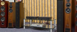
The Hi-Fi amplifier based on the TDA7294 (TDA7293) chip has good parameters and excellent sound. This amplifier is easy to make yourself. You can buy a printed circuit board for the amplifier, or you can make a printed circuit board yourself - it will turn out no worse.
Hi-Fi amplifier TDA7294
You can even say that this is a Hi-End amplifier based on the TDA7294 chip, because in the Hi-End there are amplifiers based on the same or similar chips (for example, Gain Card), but this amplifier is much better. In fact, everything that it is capable of has been squeezed out of the microcircuit. And this microcircuit is very good and the TDA7294 amplifier sounds much better than all amplifiers made in the USSR, and no worse than many European, American and Japanese amplifiers made not only in the 20th, but also in the 21st century.
Works with speakers with a resistance of 4...16 ohms. In principle, it can work with a load with a resistance of 2 ohms, but with a supply voltage of 24...26 volts and with good cooling.
Here is a review from Denmark about the sound of the amplifier:
First impression on your TDA7293 is a much more detailed and open way of playing music. This is compared against a traditional PCB for 2 x TDA without your improvements. ——————————————————————————— The first impression on your TDA7293 is a more detailed and open way of playing music. This compares to a traditional 2 TDA PCB without your improvements.
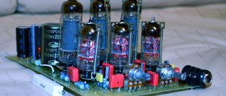
Amplifier assembled in Denmark
And this amplifier works in the USA:
Dead quiet with speakers hooked up. Dead quiet with signal inputs connected. No feedback loops or hum. Sounds very good on the test speaker system. Lower frequency response is very good. ———————————————————————— Dead silence with the speakers connected. Dead silence when signal inputs are connected. No feedback loops or hum. The sound is very good on the test speaker system. Low frequency response is very good.
Amplifier assembled in the USA
You can connect a clip-detector to the amplifier. It shows even a slight overload of the amplifier, at which the sound quality begins to decrease.
The TDA7293 chip is slightly better than the TDA7294 chip, so I recommend using it.
About the amplifier
This amplifier is not made according to a typical datasheet circuit, which is always as simple as possible and as cheap as possible. There is a lot of research behind this amplifier, some of which you can find on my website. The TDA7294 Hi-Fi amplifier uses an inverting chip (an inverting amplifier has slight advantages over a non-inverting amplifier) and has been used for many years. During this time, several hundred copies of the amplifier were manufactured, and I received many reviews about the high quality of its sound. Also, this scheme has been copied on various sites and is discussed on many Internet forums. But who can talk about this scheme better than its author?
In this article you will find all the necessary information to not only assemble the amplifier yourself, but also to make it the way you need.
Important! No recommendations are given here for the use of “correct wires,” “magic capacitors,” or other hype and marketing nonsense. In fact, most audiophile myths are meaningless. And some of them are really harmful. I'll tell you how to make a technically correct amplifier that will work well. After all, what doesn't work well can't sound good.
I will not give all the parameters of the amplifier, but only the most important ones:
- The realistically achievable maximum output power is 20...80 W. It depends on the load resistance and supply voltage.
- The amplifier gain is 23 times (27 dB). This gain is sufficient to allow operation without a preamplifier - in the vast majority of cases there is no need to further amplify the input signal. When operating from a conventional sound card or CD player, the input signal magnitude is sufficient to obtain a maximum output power of up to 70 W at 8 ohms and more than 100 W at 4 ohms. The actual power will be less, since the output power will be limited by the capabilities of the chip itself and the power supply. Therefore, you can put a volume control at the amplifier input and do without a preamplifier.
- The frequency range of the microcircuit with this connection method is approximately 3 Hz ... 450 kHz. At these frequencies the microcircuit works quite well. However, such a wide frequency range is really unnecessary and even harmful. Therefore, in my amplifier it is limited artificially. And it is approximately 20 Hz ... 50 kHz (you can adjust the frequency range of the amplifier yourself). Limiting the frequency range, firstly, improves the performance of the microcircuit and reduces the level of distortion (and dynamic distortion that can occur in amplifiers with deep negative feedback - these distortions do not occur in my amplifier at all!). Secondly, limiting the frequency range of the amplifier is useful both for the speakers connected to the amplifier and for the people who listen to music through this amplifier. How to choose the right frequency range of the amplifier is written below.
- Nonlinear distortion coefficient Kg (harmonic distortion, THD) – 0.003…0.02%.
Harmonics coefficient is one of the main parameters characterizing sound quality, therefore, for advertising purposes, they try to make it as beautiful as possible. To do this, they resort to various tricks: they measure at the frequency at which it is the smallest; measured at a “convenient” value of output power, where Kg is the smallest; not all harmonics of the distortion spectrum are taken into account. Sometimes they even measure Kg without load. At the same time, the distortion introduced by the output stage of the amplifier is significantly reduced - after all, the output current of the amplifier is zero. Often, when measuring Kg, the amplifier is powered from a special stabilized power source, which also makes it possible to obtain more beautiful advertising numbers.
I measured distortion honestly. During measurements, the amplifier operated at a 6 ohm load and was powered by a real power source. In addition, I measured Kg at different frequencies in such a way that the maximum number of harmonics in the distortion spectrum was taken into account (all harmonics with frequencies up to 95 kHz were measured). And I also measured Kg at various amplifier output power values. So, instead of one number - the value of the harmonic distortion coefficient in some specific measurement conditions, I received graphs.
Dependence of Kg on the frequency of the test signal at an output power of 20 W. All harmonics in the frequency band up to 95 kHz were taken into account. Measurement width is 24 bits.
Hi-Fi amplifier on TDA7294. Dependence of harmonic distortion THD on the frequency of the test signal.
Dependence of Kg on output power at a test signal frequency of 1 kHz.
Hi-Fi amplifier on TDA7294. Dependence of harmonic distortion THD on output power.
Note that in this graph, harmonic distortion increases significantly for output power greater than 30 W. The fact is that the amplifier during the measurements was powered from a real power source, designed for a maximum output power of 25 W. Therefore, this amplifier works perfectly with an output power of no more than 25 W.
If you require a different maximum output power, you can obtain it by using an appropriate power supply. About him below.
The distortion spectrum of the amplifier at an output power of 20 W into a 6 ohm load is very narrow.
Hi-Fi amplifier on TDA7294. THD distortion spectrum.
It contains no more than seven higher harmonics, and the amplitude of the harmonic decreases with increasing its number (the amplitudes of the 6th and 7th harmonics are less than -100 dB and these harmonics are not included in the graph). This means there is no unpleasant "transistor sound" from the amplifier.
Intermodulation distortion (IMD) spectrum measured at 18 kHz and 19 kHz at 20 W output power into 6 ohms. This is a very tough test where the amplifier is operated under the worst possible conditions. However, there is only one pair of side frequencies present in the spectrum (17 kHz and 20 kHz), which is typical only for high-quality amplifiers.
Hi-Fi amplifier on TDA7294. Spectrum of intermodulation distortion.
All spectra are narrow, which proves the high linearity of the amplifier.
This Hi-Fi amplifier based on the TDA7294 chip practically eliminates the possibility of dynamic distortion when working in conjunction with real sound-reproducing devices.
The amplifier copes well with “difficult” loads. Such a load is the speakers, some of them “lighter” and some “more difficult”. The results demonstrated by the amplifier and its comparison with some expensive amplifiers are described in the article Operation of an amplifier based on the TDA7294 chip under a difficult load.
Important! The operation of the amplifier is very dependent on the power source. What the amplifier actually does is transfer energy from the power source to the speakers. But it does this under the control of a sound signal. The energy is transferred so that the signal in the speakers is exactly the same as at the amplifier input.
Hi-Fi amplifier on TDA7294 (TDA7293) chip - circuit diagram
The Hi-Fi amplifier circuit based on the TDA7293 (TDA7294) chip is shown in the figure. Capacitor Cx does not have a serial number. This is for compatibility with the homemade PCB: I added the Cx capacitor later.
Hi-Fi amplifier on TDA7294. Schematic diagram.
Hi-Fi amplifier circuit based on TDA7293.
The description of the amplifier, its properties and operating principle are described in the article Amplifier on TDA7293 / 7294 with T-shaped feedback.
The amplifier does not contain scarce parts or any complex things. Therefore, even a beginner can assemble an amplifier with his own hands.
A drawing of a printed circuit board for making an amplifier yourself is given in the article at the link above. You can buy an industrially manufactured amplifier circuit board: Buy a printed circuit board. The following describes an option with an industrial-made printed circuit board, but all this is also suitable for an amplifier on a homemade printed circuit board.
What to pay attention to
The amplifier can use both TDA7294 and TDA7293. Depending on which chip is used, a jumper is installed on the board in the appropriate place.
- Important! The TDA7293 chip can operate in the TDA7294 chip mode. If the jumper on the board is set to the TDA7294 position, then you can install both the TDA7294 chip and the TDA7293 chip. However, not all the advantages of the TDA7293 chip will be used.
- cannot work in TDA7293 mode ! If the jumper on the board is set to the TDA7293 position, then the TDA7294 chip cannot be used!
The TDA7293 chip is slightly better than the TDA7294: it has a little more output power and sound quality, so I recommend using the TDA7293.
The capacitances of capacitors C1, C2, Cx do not have to be the same as in the diagram. You choose them yourself, based on what specific frequency properties of the amplifier you want to obtain.
The capacitance of capacitor C1 depends on the resistance of the volume control.
The amplifier as a whole (not just this printed circuit board, but the entire amplifier) will have maximum quality only if absolutely all its parts are correctly made and connected. More on this at the end of the article.
Parts used
The amplifier is easy to assemble even for beginners and is insensitive to the quality of components. But to obtain the best parameters and the best possible sound, the amplifier must be assembled from high-quality parts. High quality doesn't have to be expensive.
It is better not to use components from an unknown manufacturer: they may have poor parameters. When using such components, the amplifier may work poorly or not work at all.
The list of used parts (BOM List) can be downloaded from the following links:
In Russian:
hi-fi-7294-2020-bom-rus
In English:
hi-fi-7294-2020-bom-eng
Resistors
The amplifier uses inexpensive metal film resistors. All resistors except R9 with a power of 0.125...0.25 W. If the R9 is made in Russia, then a power of 0.5 W is sufficient. If the R9 is not made in Russia, then it is recommended to install an R9 with a power of 1 W. It is more reliable for operation at maximum power or as an instrumentation amplifier.
If you are planning a stereo amplifier or a multi-channel amplifier, then it is advisable to use resistors included in the negative feedback circuit (R2...R5) with an accuracy of 1% or better (more accurate than 0.25% are not needed). In this case, the imbalance in the volume of stereo channels will be minimal. If only resistors with an accuracy of 5% are available, then they should, if possible, be selected with the same resistance in all channels. Other resistors are not critical to the accuracy value.
Resistor R10 is of great importance. This resistor serves to separate the ground in the amplifier. But the input and output lands must not only be separated, but also necessarily connected. If resistor R10 is missing, has poor contact or too much resistance, then the amplifier will not work. Therefore, it is important that this resistor is reliable and of high quality and has the required resistance. This resistor does not need audio quality.
In principle, resistor R10 can be replaced with a jumper.
Ceramic capacitors
Ceramic capacitors C1 and Cx are made from high-quality low-voltage ceramics, with a maximum operating voltage of 50 volts. High-quality ceramics are determined by the temperature coefficient of capacitance (TCC). These capacitors must be TKE class NP0 (NP0), or C0G. Sometimes instead of the number 0 they write the letter O (NGO, NPO) - it’s the same thing. The manufacturer of the capacitors is important. It is better not to use noname capacitors. For example, Murata, Vishay, EPCOS are suitable. You can use Russian-made capacitors.
Selecting the capacitance of capacitors C1 and Cx
Capacitor C1 cuts the high frequencies entering the amplifier input (it forms a low-pass filter), and thereby suppresses high-frequency interference. However, this narrows the operating frequency range of the amplifier in the high frequency region. The capacitance of capacitor C1 is selected based on the resistance value of the volume control and the required cutoff frequency of the low-pass filter (LPF), which forms this capacitor together with resistor R1 and the resistance of the volume control. I offer a choice of one of two frequencies: 50 kHz and 70 kHz.
The cutoff frequency of 50 kHz is selected to provide stronger suppression of possible high-frequency noise coming into the input.
The sources of such interference can be both communication equipment (mobile devices, Wi-Fi and Bluetooth, radio communications, television), and other industrial and household devices.
But high-frequency interference arises not only from interference from radio communication systems. Ultrasound may be coming to the amplifier input from the CD player (more precisely, its DAC) - the sampling frequency is not sufficiently filtered. Or, for example, from a vinyl record player - where ultrasound is generated when the pickup stylus moves along the groove of the record.
If you are sure that there is no high-frequency interference, then the cutoff frequency of the input filter can be set to 70 kHz. In this case, the amplifier can have a maximum operating frequency of approximately 50 kHz.
By selecting an input filter cutoff frequency of 50 kHz, the amplifier can have a maximum operating frequency of approximately 40 kHz.
The capacitance values of capacitor C1 depending on the resistance value of the volume control and the required cutoff frequency of the input filter.
| Volume control resistance, kOhm | Capacitance of capacitor C1 required to obtain the cutoff frequency of the input filter 50 kHz, pF | Capacitance of capacitor C1 required to obtain the cutoff frequency of the input filter 70 kHz, pF |
| There is no volume control at the amplifier input: a preamplifier is used or the volume is controlled by the computer sound card | 2200 | 1500 |
| 5 | 1200 | 820 |
| 10 | 820 | 560 |
| 20 | 510 | 360 |
| 30 | 360 | 240 |
| 50 | 220 | 160 |
| 100 | 120 | 82 |
Capacitor Cx performs several functions simultaneously:
- — improves the stability of the amplifier;
- — increases the depth of negative feedback (NFB) at high frequencies and reduces distortion;
- — at high frequencies it boosts the signal in the OOS circuit, which virtually eliminates the possibility of dynamic distortion.
Capacitor Cx, like C1, reduces the upper cutoff frequency of the amplifier.
Both capacitors operate at frequencies above 20 kHz, so they have virtually no effect on the reproduction of high audio frequencies. The combined use of these capacitors results in no dynamic distortion occurring in the amplifier at all. However, some people want an amplifier with a frequency range of up to 40...50 kHz. This is their right, despite the fact that most people cannot hear signals above 20 kHz (a small study on this topic was published in the article Studying the Upper Limit of Hearing). In addition, the influence of any filters on the frequency response occurs smoothly, so even if the upper limit frequency of the amplifier is 50 kHz, at a frequency of 20 kHz the amplitude-frequency response (AFC) of the amplifier has a block, albeit microscopic.
Selecting the capacitance value of the capacitor Cx.
Option 1. The cutoff frequency of the input low-pass filter is 70 kHz.
| Capacitor capacity Cx, pF | Upper limit frequency of the amplifier at the level of -3 dB, kHz | Amplifier frequency response at 20 kHz, dB |
| 47 | 54 | 0,5 |
| 56 | 50 | 0,6 |
| 68 | 46 | 0,65 |
| 75 | 44 | 0,7 |
| 82 | 42 | 0,8 |
Option 2. The cutoff frequency of the input low-pass filter is 50 kHz.
| Capacitor capacity Cx, pF | Upper limit frequency of the amplifier at the level of -3 dB, kHz | Amplifier frequency response at 20 kHz, dB |
| 47 | 42 | 0,8 |
| 56 | 40 | 0,9 |
| 68 | 37 | 1 |
A frequency response rolloff at a frequency of 20 kHz of 0.8 dB, and even more so 1 dB may seem too large. But in reality it is invisible:
- it is below the hearing sensitivity threshold at this frequency,
- at a frequency of 20 kHz there is practically no sound,
- not all people hear this frequency
In fact, the capacitance of these capacitors may differ slightly from the specified value. A change in the capacitance of the frequency-setting capacitors by 10...20% will not be noticeable. But if you change the capacitance of these capacitors, then it is still better to expand the frequency response: increase C1, and decrease C2 and Cx.
Film capacitors
Capacitors C2, C4, C6, C7, C9 are lavsan film (other names for dielectric are mylar, polyester, MKT).
The most important capacitor for sound is C2. It must be of good quality. In this place, you can use a capacitor with a polypropylene dielectric (MKP). You most likely won't notice any difference in sound, but you'll still be pleased that you did your best to get high quality sound.
In fact, to get good sound, it is much more important to use the correct power supply and the correct installation of the amplifier blocks inside the case. But in any case, capacitor C2 should not be bad.
Capacitor C6 has the least effect on sound quality. In principle, it can even be excluded from the scheme. However, even in this place it is not recommended to use a bad capacitor.
Capacitor C4 improves the stability of the amplifier. Its maximum operating voltage can be up to 250 volts. If there is a choice, then it is recommended to choose the largest size of all available capacitors, but such that it can be normally installed on the board. When the amplifier is operating, a relatively large high-frequency current passes through this capacitor, and the capacitor can heat up. The larger the capacitor, the less heat it generates. Be reasonable! The capacitor size of 7.5 mm is quite sufficient!
Capacitors C7 and C9 help capacitors C8 and C10 supply power to the amplifier at high frequencies. The capacity of these capacitors is 2.2...4.7 μF, the maximum operating voltage is at least 63 volts. Capacitors must be of high quality to work well. The larger the capacity the better, but be smart. It is important that the length of the leads of these capacitors is minimal - the inductance of long leads will interfere with their operation. Therefore, a smaller capacitor with short leads will perform better than a larger capacitor with long leads.
"Green" capacitors can be used in positions C4 and C6.
Good capacitors don't have to be expensive. Moreover, it is better to use “regular” capacitors from a well-known manufacturer than capacitors from an unknown one.
Selecting the capacitance of capacitor C2
The capacitance value of capacitor C2 determines both the lower limiting frequency of the amplifier and the roll-off of the amplifier’s frequency response at low frequencies. This capacitor, together with the input impedance of the amplifier, forms a high-pass filter (HPF), passing frequencies above 10...25 Hz and suppressing frequencies below this value.
What the amplitude-frequency response looks like in the low-frequency region at different values of the capacitance of capacitor C2 is shown in the figure (high frequencies in this figure are shown conventionally).
Frequency response of the amplifier at different values of C2.
Amplifier parameters depending on the capacitance of capacitor C2.
| Capacitance of capacitor C2, µF | Lower limit frequency of the amplifier at the level of -3 dB, Hz | Amplifier frequency response at 20 Hz, dB | Amplifier frequency response at 25 Hz, dB | Amplifier frequency response at 30 Hz, dB |
| 0,22 | 22 | 3,3 | 2,5 | 1,8 |
| 0,33 | 14 | 1,8 | 1,3 | 0,9 |
| 0,47 | 10 | 0,9 | 0,6 | 0,5 |
| 0,68 | 7 | 0,5 | 0,3 | 0,2 |
| 1,0 | 5 | 0,2 | 0,2 | 0,1 |
| 1,5 | 3 | 0,1 | 0,1 | 0,05 |
Strategy for choosing the capacitance value of capacitor C2
The larger the capacitance C2, the lower the lower cutoff frequency of the amplifier (that is, the amplifier amplifies lower frequencies quite strongly), and the smaller the frequency response rolloff at low audio frequencies.
But to say that the larger the C2 capacity, the better the low frequencies are reproduced, it will be incorrect.
Indeed, if the frequency response of your speakers starts at 40 Hz, then everything that happens below 30 Hz should not bother you.
It would be more correct to say this: if the capacitance of capacitor C2 is less than a certain value, then the volume of the lowest frequencies in the audio range will decrease. For example, if C2 = 0.68 μF, then the frequency response rolloff at a frequency of 20 Hz is 0.5 dB - this is much less than the hearing sensitivity limit at this frequency, so we probably won’t hear such a rollover. In this case, the amplifier reproduces frequencies starting from 7 hertz. If the capacitance of capacitor C2 is reduced to 0.1 μF, then the volume at the very, very low frequencies will decrease slightly. We will notice this only with a very good soundtrack and excellent speakers. And then only during comparative listening. But let's notice!
Are such low frequencies necessary?
They say that if the amplifier reproduces absolutely all low frequencies, starting with constant voltage, then this improves the sound. They even talk about the constant component of sound. These are all advertising and marketing gimmicks that have nothing to do with reality.
The constant component of sound is atmospheric pressure, and no speaker can change it. And infrasound frequencies, which can reach the amplifier output and be reproduced by speakers, are harmful to humans. For example, infrasound frequencies that coincide with the frequency of the alpha rhythm of the brain (frequencies 7 ... 15 Hz) can cause headaches, disorientation and even panic.
A large number of infrasound frequencies are generated when playing vinyl records. Especially old ones: warped and eccentric. But even when playing new gramophone records, infrasound still occurs: it is created both by the player’s engine (rumble) and by the physical processes of friction of the stylus in the groove. Douglas Self wrote about this in detail in his book Electronics for Vinyl.
Fortunately, most speakers at these frequencies cannot create significant sound pressure, but it is better if these frequencies are cut off in the amplifier.
Another reason for refusing to reproduce very low frequencies is the physical processes in the loudspeakers. For equal volume as the frequency decreases, the diffuser stroke increases in proportion to the second power. That is, if the frequency is halved, the diffuser stroke should increase 4 times. In fact, the cone stroke increases even more due to a decrease in hearing sensitivity at the lowest frequencies. But the linear range of the loudspeaker is limited, so significant low frequencies can overload the loudspeaker, and the entire sound will be distorted.
Speakers with a bass reflex (PI) are especially susceptible to this phenomenon - at frequencies below the PI tuning frequency, the diffuser stroke is not limited in any way. In this case, the speaker practically does not emit sound, since an acoustic short circuit occurs: the sound emitted by the loudspeaker and the sound emitted by the bass reflex are subtracted from each other almost to zero.
The result is that there is no audible overload and the sound is poor. So from this point of view, limiting the reproduction of very low frequencies has a positive effect on the operation of the entire system, on sound quality and on human perception of sound.
On the other hand, the higher the cutoff frequency of the amplifier, the worse the transient processes when reproducing a low-frequency musical signal (not indefinitely, but up to certain limits). The bass, especially in bass reflex speakers, tends to be a little tighter.
So from this point of view, it is also undesirable to greatly increase the lower cutoff frequency of the amplifier.
What to do?
The output is this: the cutoff frequency of the high-pass filter formed by capacitor C2 should be 2...3 times less than the lower operating frequency of the speakers connected to this amplifier. But not lower than 10 Hz. And don’t be afraid of blocking the frequency response at low frequencies! A rollover of 1 dB at frequencies below 30 Hz is not noticeable by ear.
Personally, I most often use capacitor C2 with a capacity of 0.33 μF, and less often with a capacity of 0.47 μF.
To select the capacitance of capacitor C2, use this table.
| Amplifier purpose | Capacitance of capacitor C2, µF |
| Speakers of average quality with a lower operating frequency of 50...80 Hz. Especially recommended for vinyl playback | 0,22 |
| Higher quality speakers with a lower operating frequency of 30...40 Hz High quality speakers with powerful bass and a lower operating frequency of 20...30 Hz when playing vinyl | 0,33 |
| High-quality speakers with powerful bass and a lower operating frequency of 20…30 Hz. Quality subwoofer for vinyl playback | 0,47 |
| Quality subwoofer when playing vinyl Quality subwoofer | 0,68 |
| High quality subwoofer | 1,0 |
| Subwoofer for maniacs | 1,5 |
For myself and to order (in agreement with customers after studying their requirements and their equipment), I usually make two versions of the amplifier (a pre-amplifier with a volume control is used):
- “Standard” with the following set of element values: C1 = 2200 pF (input filter cutoff frequency 50 kHz), Cx = 47 pF, C2 = 0.33 µF polypropylene (MKP) Epcos or K78-19.
- "With extended frequency range." With this set of element values: C1 = 1500 pF (input filter cutoff frequency 70 kHz), Cx = 47 pF, C2 = 0.47 µF polypropylene (MKP) Epcos or K78-19.
The amplitude-frequency characteristics of these two amplifier options are shown in the figure.
Electrolytic capacitors
Positions C3 and C5 should contain regular high-quality capacitors. Capacitor C3 sets the turn-on time of the amplifier and does not affect the sound. But if it is of poor quality or has a large leak, then the amplifier may not turn on. With a poor-quality capacitor C5, the maximum undistorted output power is much less than it could be.
Capacitors C8 and C10 perform three functions at once:
- Additionally, supply voltage ripple is suppressed.
- They feed the amplifier at peak volumes. Capacitors C8 and C10 are installed very close to the chip, and the conductors coming from these capacitors are very short. Therefore, these conductors have very low resistance and inductance. As a result, if necessary, all the energy from these capacitors quickly enters the microcircuit and is transmitted to the output of the loudspeakers.
- They pass loudspeaker current through themselves at medium and high frequencies. As a result, this current is closed through the shortest path.
All these functions are actually combined. Physically this is one function. I separate them mentally to make it easier to analyze them.
The functions of capacitors C8 and C10 are very important, so these capacitors must be of good quality. It is very useful to use Low ESR or Low Impedance capacitors in this position.
However, be reasonable! The importance of the quality of capacitors C8 and C10 is often exaggerated. There is no point in using exotic “magic” supercapacitors. Good capacitors from a reliable manufacturer are quite enough. It is important that these capacitors are properly soldered to the board. Moreover, they have leads of minimal length, which means minimal resistance and inductance.
It is not recommended to use capacitors C8 and C10 with a capacity of less than 1000 µF. It is also not recommended to significantly increase their capacity. You can use capacitors with a capacity of 2200 µF, but with a high-quality power source there will be no difference.
At high frequencies, electrolytic capacitors C8 and C10 are assisted by film capacitors C7 and C9, so these capacitors must also be of good quality.
↑ Disadvantages of the scheme and ways to improve it
The main disadvantages of the classically designed Lin circuit are the insufficient gain without negative feedback, with the bandwidth and slew rate of the output voltage leaving much to be desired.
Although harmonic distortion at 1 kHz does not exceed one percent, above 1 kHz the distortion increases fourfold for every octave increase in signal frequency. Intermodulation distortion turns out to be three times higher than nonlinear distortion, so this circuit demonstrates only the very initial level of high-quality sound, requiring improvements. Subsequently, this typical UMZCH circuit was subjected to many improvements affecting all components: differential stage, voltage amplifier and output stage. A significant improvement in the characteristics of the differential cascade can be achieved by replacing the resistive quasi-current generator (R4) with a transistor one. Stability, performance, gain, suppression of common mode signals and interference in power circuits are increased by approximately an order of magnitude. The next step to improve the linearity and dynamic characteristics of the input differential stage is to use current reflectors and current mirrors in the collector load (instead of resistors R2, R3). Essentially, the current mirror balances two unbalanced current paths, providing significant improvements in linearity and increasing common mode rejection as well as ripple rejection.
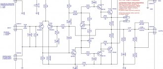
Replacing the resistive load (R10, R11) in the VT3 voltage amplification stage with a transistor stable current generator gives the same order of performance improvement as in the differential stage. To increase the DC gain, a circuit technique is used - a buffer emitter follower; to increase the frequency of the main pole - a cascode circuit. Increasing the depth of overall feedback in the audio frequency range without increasing the cutoff frequency of the entire amplifier is achieved by bipolar correction in the voltage amplification stage. The output stage (Fig. 1) operates in class AB and is made of triplets of transistors according to a quasi-complementary circuit. The use of three transistors instead of the desired two is caused primarily by the low values of the transistor transmission coefficients with a low load resistance (speaker system, Rn = 4 Ohms).
Improvements in the operation of the output stage are achieved by using an element base specially designed for sound reproduction purposes:
- complementary transistors (for example,
2SC3281/2SA1302
from Toshiba), high-power complementary multi-emitter transistors (abbreviation LAPT,
2SC3284/2SA1303
from Sanken);
— powerful bipolar transistors with insulated gate (IGBT, for example, GT20D201/GT20D101
from Toshiba);
— field-effect transistors ( 2SK1058/2SJ162
) and other semiconductor devices.
An important improvement can be considered the release of integrated circuits for audio power amplifiers, which significantly simplified the application with characteristics comparable to those of devices using discrete components. As an example in Fig. Figure 2 shows a simplified circuit of the TDA2050
STMicroelectronics
company [2].
Power amplifiers TDA2006, TDA2030, TDA2040
and others have a similar circuit [3-7].
Rice. 2. Functional diagram of the integrated audio power amplifier TDA2050
To increase the input resistance, the differential stage (DC) is made on composite emitter followers VT4, VT5 and VT9, VT10. The optimal choice of DC operating mode and the use of pnp transistors, which have a lower volumetric base resistance compared to transistors of the opposite structure, made it possible to obtain an insignificant noise level (the typical noise voltage referred to the input in the frequency range from 22 Hz to 22 kHz is no more 5 µV).
A current mirror VT7, VT8 is installed in the collector load of the DC, and a current source VT6 is included in the emitter circuit. The voltage amplification stage is also made using a composite circuit using transistors VT11, VT13, which made it possible to obtain a high gain without feedback, more than 80 dB. Capacitor C2 performs single-pole frequency correction. To increase the phase margin, the voltage amplification stage and the output stage are covered by another frequency correction circuit through capacitor C1 (the so-called inclusive frequency correction).
The output stage of the microcircuit (VT18, VT20 and VT15, VT16, VT21) is made according to a quasi-complementary circuit, characteristic of amplifier technology of the seventies of the last century. Inclusive frequency correction helps to equalize the phase characteristics of the asymmetrical arms of the output stage, resulting in an acceptable balance between the manufacturability of the microcircuit (read: price) and the implemented fairly high technical characteristics.
Installing the TDA7294 chip
Depending on the chip used, a jumper is installed on the board in the desired position.
Installing the TDA7294 or TDA7293 jumper
If the jumper is set to TDA7293, the empty square pad labeled TDA7294 can be filled with solder.
Filling the pad
It will be very, very little, but better.
The chip must be installed on a radiator with an area of at least 700 square centimeters. When installing the microcircuit on a radiator, you must use thermal paste. The radiator must be freely cooled by air.
Important! The housing of the microcircuit is connected to the minus of the power supply, therefore, in order to avoid a short circuit of the power source, you must either install the microcircuit through an insulating gasket (and isolate the screw that secures the microcircuit to the radiator), or reliably isolate the radiator from the housing.
In the first version, the microcircuit is cooled a little worse. In the second, it is possible to accidentally short-circuit an energized radiator to the housing.
Do what is most convenient for you.
Several microcircuits can be installed on one radiator, and the area of the radiator can be increased by as many times as the number of microcircuits installed on it. But the power wires must be suitable for each of the amplifier boards . You cannot “pass power” from one microcircuit to another through a radiator! The fact that the microcircuit's flange is connected to the power supply negative does not mean that the microcircuit can receive power through its flange!
You can attach the board to the radiator simply by screwing the chip to it. This method is applicable if the board does not use heavy exotic components and if there is no vibration during operation of the amplifier. An example of such board mounting in the amplifier case is shown on the Four-channel amplifier page.
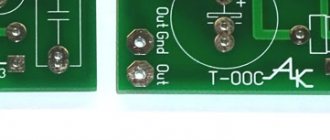
The board dimensions and connection dimensions are shown in the figure. The flange of the microcircuit protrudes beyond the dimensions of the board by 1...2 millimeters, depending on how the microcircuit is oriented during soldering.
For more reliable fastening, you can use a special mounting hole for a screw with an M3 thread. This hole is isolated from the circuit.
The principle of using this hole is quite simple, the main thing is that nothing closes.
Mounting idea
↑ What is power and signal ground?
Let's deal with grounding in the UMZCH.
It should be understood that there are two types of lands: power (current) and signal (potential). Currents flow through the former, but practically none through the latter (small signal and bias currents in the differential stage). As soon as a piece of current ground gets into the potential ground circuit (sometimes a few millimeters are enough!), interference and distortion of the output signal occurs. I came across a situation where one centimeter of common signal and power ground increased the harmonic coefficient by two orders of magnitude - from thousandths of a percent to tenths! The finite resistance of the “ground” buses is to blame, which leads to the fact that current pulses along the common wire from the output of the amplifier can reach its input. There are three effective ways to combat such interference:
— increasing the cross-section of the common wire busbars; - connection of all conductors going to a common wire at one point; — galvanic isolation of the common wire of the input stage from the power bus of the output stages of the amplifier.
The latter is possible in an UMZCH with a differential cascade. The terminals R1, R2, C2 and C3 are connected to the common wire of the signal source, see Fig. 4 (signal ground). All other conductors connected to the common wire are connected to the power ground. By the way, some designers use not two, but three “grounds” - signal, intermediate and power. To prevent the amplifier from failing if the signal source is accidentally turned off, both ground buses are connected on the board by resistor R6. Its resistance is chosen as a compromise between the effect of interference from the “power” ground and the effect on the depth of negative feedback (practical choice is units ... tens of Ohms). In cases where the signal ground forms a closed circuit, it plays the role of an antenna, causing the appearance of interference that is difficult to eliminate.
The view of the mounted UMZCH module and the power supply for it, included in the annotation of the article, should strengthen the desire to immediately assemble this design yourself.
Connecting the volume control
If there is no preamplifier, then the volume control is connected directly to the amplifier. It is important that the input circuits do not have contact with ground or the amplifier housing.
It is recommended to use a variable resistor (potentiometer) with a resistance of 30...50 kOhm as a regulator. The maximum resistance values of the volume control are 5...100 kOhm, but a slight deterioration in sound quality is possible.
It is better to use a variable resistor with an exponential dependence of the resistance on the angle of rotation. Then, when you rotate the control knob, the volume will change in proportion to the angle of rotation. Such Russian-made variable resistors are designated by the letter B, and resistors not produced in Russia are designated by the letter A.
Power supply for amplifier
The operation of the amplifier is very dependent on the power source. What the amplifier actually does is transfer energy from the power source to the speakers. But it does this under the control of a sound signal. The energy is transferred so that the signal in the speakers is exactly the same as at the amplifier input. How to make a correct and good power supply is described in the article Power supply for TDA7294.
How to properly make an amplifier and power supply to get maximum sound quality is written in these articles:
More information about amplifiers and sound enhancement:
Links given in the article
Amplifier based on TDA7293 / 7294 with T-shaped OOS
Power supply for TDA7294
Amplifier ground sharing
Connecting blocks inside the amplifier
Operation of an amplifier based on the TDA7293 (TDA7294) chip with a “difficult” load
Clip-detector for amplifier on TDA7293
Study of the upper limit of hearing
Information to better understand the operation of the amplifier and get maximum sound quality
Hi-Fi amplifier based on TDA7294 chip
Clipping in an amplifier
Amplifier power supply calculation
Transformer for powering the amplifier
The right straightener
Rectifier for an amplifier or the saga of a fast diode
Separate power supply for stereo amplifier channels
Capacitor array - myths and reality
Mute and StandBy modes in the TDA7294 / TDA7293 chip
↑ Setting up
An amplifier assembled from serviceable parts does not require adjustment. Before turning on the power amplifier for the first time, power must be supplied through a current-limiting circuit. I use this circuit to debug my designs, Fig. 8 [10].
Rice. 8. Circuit for debugging UMZCH: C1, C2 – 1000 µF x 50 V; R1, R2 - 30...100 Ohm, power 7.5...50 W
Monitor the voltage drop across the resistors of the current-limiting circuit R1, R2 - it should correspond to a quiescent current of 70...100 mA. If this is the case, the auxiliary circuit is turned off and power is supplied from the power supply. If the current consumption of the UMZCH exceeds the specified value, look for the reason: a faulty element or installation errors!