Audio power amplifier circuit
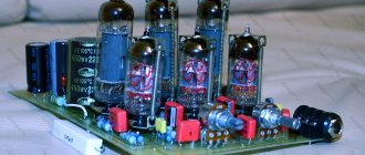
High quality audio power amplifier circuit
Audio preamplifier circuit
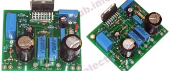
Power supply and power amplifier protection circuit
This amplifier consists of:
- Input selector for six relays, a 6-position ALPS rotary switch was used for control.
- Preamplifier with low noise transistors and high quality capacitors.
- Loop filter - a miniature relay was used for activation.
- The power supply is bipolar and has sufficient power.
Transistors - TIP35 / TIP36, the end of course requires large radiators. Additionally, it was decided to use active cooling in the form of a fan, but tests showed that this is not necessary.
↑ Details, installation and setup
Coil L1 is wound on a mandrel with a diameter of 10 mm and contains 13 turns of PEL, PEV wire with a diameter of 1.0 mm.
Resistor R10 is located inside coil L1. Details (for two amplifier channels)
DA1 — LM1875T NSC chip, TO220-5 package – 2 pcs., DA2 — OP07CP (PBF) chip, DIP8-300 package – 2 pcs., DA3 — 78L15 positive polarity stabilizer chip, TO92 package – 2 pcs., DA4- Chip negative polarity stabilizer 79L15, TO92 housing - 2 pcs., Collet socket dip 8, SCSM-8 (for DA2 chip) - 2 pcs., VD1, VD2 - SF56, HER508 - 2 pcs. R1 – Res.0.25-1 m (Brown, black, green, golden) – 2 pcs., R2, R6 – Res.0.25-22 kOhm (Red, red, orange, golden) – 4 pcs., R3, R4 – Res.0.25-1 kOhm (Brown, black, red, gold) – 4 pcs., R5 – Res.0.25-220 kOhm (Red, red, yellow, gold) – 2 pcs., R7 – Res.0.25-10 Ohm (Brown, black, black, gold) – 2 pcs., R8, R9 – Res.0.25-2.4 m (Red, yellow, green, gold) – 2 pcs. ., R10 – Res. 1-10 Ohm (Brown, black, black, gold) – 2 pcs. C1 – Cond. 1µ/63V K73-17 – 2 pcs., C2 – Cond. 390p/63V J EVOX (NPO 390 pF 5% ceramic imp.) – 2 pcs., C3, C4 – Cond. metal film imp. 2.2µ/100V K73-17 B32522-C1225-J (2.2µ/63V K73-17 B32522-C225-J) – 4 pcs., C5 – Cond. 0.22/63V K73-17 – 2 pcs., C6, C9, C10 – Cond.0.1µ/63V K73-17 (K73-44b) – 6 pcs., C7, C8 – Cond. electrolytic 10/25V 0511, +105°C – 4 pcs., C11, C12 — Cond. electrolytic 220/35V, 1016, +105°C – 4 pcs., Terminal block 2K pitch 5 mm per board dg301-2 – 2 pcs., Terminal block 3K pitch 5 mm per board dg301-3 – 2 pcs., PEL, PEV wire with a diameter of 1 mm - 1 m, Printed circuit board 55x80 mm - 2 pcs.
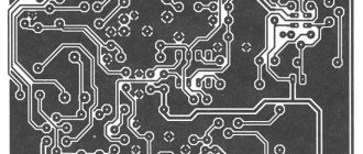
The placement of parts on the printed circuit board is shown in Fig. 6.
Fragment excluded. The full version is available to patrons and full members of the community.
Rice. 6. Location of elements of the improved UMZCH on the printed circuit board
Installing parts on a printed circuit board will not cause difficulties if you follow a certain assembly sequence. First, resistors are installed. Considering that most of them are color-coded, it is useful to check its resistance with a tester before installing a resistor on a printed circuit board.
Then install a wire jumper, a socket for the DA2 microcircuit, microcircuits, capacitors, terminal blocks and elements L1, R10.
Check the installation, paying special attention to the correct installation of microcircuits and oxide capacitors on the printed circuit board. It is advisable to carry out a visual inspection of soldering, identify and eliminate missing solders, solder jumpers, and defects in the installation of elements.
Attach the DA1 chip to the radiator, connect the wires to the terminal blocks and turn on the amplifier for the first time. In the absence of “surprises”, check the presence of supply voltages of ±15 V at the outputs of the DA3 and DA4 stabilizer microcircuits, and “zero” at the amplifier output; Then they connect the speakers, the signal source and listen to music.
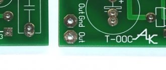
Printed circuit boards for assembly
24 V power supply and protection. The power supply supplies voltage to control the relay. To avoid unpleasant sound effects when turning on / off the amplifier, protection has been added in the form of a delay in turning on and immediately turning off the speakers and protection against the occurrence of constant voltage at the speaker output. Two relays allow you to connect two loudspeakers.
Everything is assembled in the original case from the ULF.
AudioKiller's site
The newest and best circuit with a detailed description and selection of components is here: Hi-Fi amplifier on the TDA7294 chip.
And it's real! The amplifier, despite its relative simplicity, provides fairly high parameters. Actually, to tell the truth, “chip” amplifiers have a number of limitations, so “loose” amplifiers can provide higher performance. In defense of the microcircuit (otherwise why do I use it myself and recommend it to others?) we can say:
- the circuit is very simple
- and very cheap
- and requires virtually no adjustment
- and you can assemble it in one evening
- and the quality is superior to many amplifiers of the 70s ... 80s, and is quite sufficient for most applications (and even modern systems under $300 can be inferior to it)
- thus, the amplifier is suitable for both beginners and experienced radio amateurs (for example, I once needed a multi-channel amplifier to test an idea. Guess what I did?).
In any case, a poorly made and incorrectly configured amplifier in bulk will sound worse than a microcircuit amplifier. And our task is to make a very good amplifier. It should be noted that the sound of the amplifier is very good (if it is made correctly and powered correctly), there is information that some company produced Hi-End amplifiers based on the TDA7294 chip ! And our amplifier is no worse!!!
Main settings
I will specifically measure the parameters of the microcircuit and publish it separately (Operation of an amplifier on the TDA7294 microcircuit with a “difficult” load). Here I will say that the microcircuit worked stably with an active load of 2...24 ohms, with an active resistance of 4 ohms plus either a capacitance of ~15 μF or an inductance of ~1.5 mH. Moreover, on capacitive and inductive loads (not as strong as described above), the distortion remained small. It should be noted that the amount of distortion is highly dependent on the power source, especially with a capacitive load.
| Parameter | Meaning | Measurement conditions |
| Rout.max, W (long-term sinusoidal) | 36 | Supply voltage +- 22V, Rн = 4 Ohm |
| Frequency range at -3 dB level | 9 Hz - 50 kHz | Rн = 8 Ohm, Uout = 4 V |
| Kg, % (using RMAA 5.5 program) | 0,008 | Rн = 8 Ohm, Рout = 16 W, f = 1 kHz |
| Sensitivity, V | 0,5 | Rout.max = 50 W, Rn = 4 Ohm, Uip = +-27 V |
Scheme
The circuit of this amplifier is practically a repetition of the switching circuit offered by the manufacturer. And this is no coincidence - who knows better how to turn it on. And there certainly won’t be any surprises due to non-standard activation or operating mode. Here it is, the diagram:
I’ll admit right away - you won’t get any 80 watts (and especially 100 watts) from it. Realistically 40-60, but these will be honest long-term cotton wool. In a short-term impulse you can get much more, but this will already be RMPO power, by the way, also honest (80-120 W). In “Chinese” watts it will be several thousand, if anyone is interested. Five thousand. It all depends heavily on the power source, and later, I will write how to increase the power while also improving the sound quality. Watch out for advertisements!
Description of the scheme
The input circuit R1C1 is a low pass filter (LPF), cutting off everything above 90 kHz. It is impossible without it - the 21st century is, first of all, the century of high-frequency interference. The cutoff frequency of this filter is quite high. But this is on purpose - I don’t know what this amplifier will be connected to. If there is a volume control at the input, then it will be just right - its resistance will be added to R1, and the cutoff frequency will decrease (the optimal value of the volume control resistance is ~10 kOhm, more is better, but the regulation law will be violated).
Next, the R2C2 chain performs the exact opposite function - it does not allow frequencies below 7 Hz to enter the input. If this is too low for you, the C2 capacity can be reduced. If you get too carried away with reducing capacity, you may be left without any low frequencies at all. For the full audio range, C2 must be at least 0.33 µF. And remember that capacitors have a fairly wide range of capacitances, so if it says 0.47 microfarads, it could easily turn out to be 0.3! And further. At the lower end of the range, the output power is reduced by 2 times, so it is better to choose it lower:
C2[uF] = 1000 / ( 6.28 * Fmin[Hz] * R2[kOhm])
Resistor R2 sets the input resistance of the amplifier. Its value is slightly larger than according to the datasheet, but this is also better - too low an input impedance may “not be liked” by the signal source. Please note that if a volume control is turned on in front of the amplifier, then its resistance should be 4 times less than R2, otherwise the law of volume control will change (the volume value depends on the angle of rotation of the control). The optimal value of R2 lies in the range of 33...68 kOhm (higher resistance will reduce noise immunity).
The amplifier connection circuit is non-inverting. Resistors R3 and R4 create a negative feedback circuit (NFC). The gain is:
Ku = R4 / R3 + 1 = 28.5 times = 29 dB
This is almost equal to the optimal value of 30 dB. You can change the gain by changing resistor R3. Please note that you cannot make Ku less than 20 - the microcircuit can self-excite. It’s also not worth doing it more than 60 - the depth of feedback will decrease and the distortion will increase. With the resistance values indicated in the diagram, with an input voltage of 0.5 volts, the output power at a 4 ohm load is 50 W. If the sensitivity of the amplifier is not enough, then it is better to use a preamplifier.
The resistance values are slightly higher than those recommended by the manufacturer. Firstly, this increases the input impedance, which is nice for the signal source (to obtain maximum DC balance, R4 must be equal to R2). Secondly, it improves the operating conditions of the electrolytic capacitor C3. And thirdly, it enhances the beneficial effects of C4. More on this. Capacitor C3 in series with R3 creates 100% OOS for direct current (since its resistance to direct current is infinite, and Ku is equal to unity). In order for the influence of C3 on the amplification of low frequencies to be minimal, its capacitance must be quite large. The frequency at which the influence of C3 becomes noticeable is:
f [Hz] = 1000 / (6.28 * R3 [kOhm] * C3 [uF] ) = 1.3 Hz
This frequency should be very low. The fact is that C3 is electrolytic polar, and it is supplied with alternating voltage and current, which is very bad for it. Therefore, the lower the value of this voltage, the less distortion introduced by C3. For the same purpose, its maximum permissible voltage is chosen to be quite large (50V), although the voltage on it does not exceed 100 millivolts. It is very important that the cutoff frequency of the R3C3 circuit is much lower than the input circuit R2C2. After all, when the influence of C3 manifests itself due to an increase in its resistance, then the voltage on it increases (the output voltage of the amplifier is redistributed between R4, R3 and C3 in proportion to their resistances). If at these frequencies the output voltage drops (due to a drop in the input voltage), then the voltage at C3 does not increase. In principle, you can use a non-polar capacitor as C3, but I can’t say for sure whether this will improve the sound or worse: a non-polar capacitor is “two in one” polar ones connected back to back.
Capacitor C4 bypasses C3 at high frequencies: electrolytes have another drawback (in fact, there are many drawbacks, this is the price to pay for the high specific capacitance) - they do not work well at frequencies above 5-7 kHz (expensive ones are better, for example Black Gate, which costs 7-7 kHz). 12 euros per piece works well at 20 kHz). Film capacitor C4 “takes over the high frequencies,” thereby reducing the distortion introduced to them by capacitor C3. The larger the C4 capacity, the better. And its maximum operating voltage can be relatively small.
Circuit C7R9 increases the stability of the amplifier. In principle, the amplifier is very stable, and you can do without it, but I came across instances of microcircuits that worked worse without this circuit. Capacitor C7 must be designed for a voltage no lower than the supply voltage.
Capacitors C8 and C9 perform the so-called voltage boost. Through them, part of the output voltage flows back into the pre-terminal stage and is added to the supply voltage. As a result, the supply voltage inside the chip is higher than the voltage of the power supply. This is necessary because the output transistors provide an output voltage 5 volts less than the voltage at their inputs. Thus, in order to get 25 volts at the output, you need to apply a voltage of 30 volts to the gates of the transistors, but where can you get it? So we take it from the exit. Without the voltage booster circuit, the output voltage of the microcircuit would be 10 volts less than the supply voltage, but with this circuit it would be only 2-4. Film capacitor C9 takes over the work at high frequencies, where C8 performs worse. Both capacitors must withstand a voltage not lower than 1.5 times the supply voltage.
Resistors R5-R8, capacitors C5, C6 and diode D1 control the Mute and StdBy modes when the power is turned on and off (see Mute and StandBy modes in the TDA7294 chip). They provide the correct sequence for turning on/off these modes. True, everything works fine even with the “wrong” sequence, so such control is needed more for your own pleasure.
Capacitors C10-C13 filter the power. Their use is mandatory - even with the best power supply, the resistance and inductance of the connecting wires can affect the operation of the amplifier. With these capacitors, no wires are a problem (within reasonable limits)! There is no need to reduce the capacity. Minimum 470 µF for electrolytes and 1 µF for film ones. When installing on a board, it is necessary that the leads are as short as possible and well soldered - do not skimp on solder. All these capacitors must withstand a voltage not lower than 1.5 times the supply voltage.
And finally, resistor R10. It serves to separate the input and output land. “On the fingers” its purpose can be explained as follows. A large current flows from the amplifier output through the load to ground. It may happen that this current, flowing through the “ground” conductor, will also flow through the section through which the input current flows (from the signal source, through the amplifier input, and then back to the source along the “ground”). If the resistance of the conductors was zero, then there would be no problem. But the resistance, although small, is not zero, so a voltage will appear at the resistance of the “ground” wire (Ohm’s law: U=I*R), which will add up to the input. Thus, the output signal of the amplifier will go to the input, and this feedback will not bring anything good, only all sorts of nasty things. The resistance of resistor R10, although small (the optimal value is 1...5 Ohms), is much greater than the resistance of the ground conductor, and through it (the resistor) hundreds of times less current will flow into the input circuit than without it.
In principle, if the board layout is good (and I have a good one), this will not happen, but on the other hand, something similar can happen on a “macro scale” along the signal source-amplifier-load circuit. A resistor will help in this case too. However, it can be completely replaced with a jumper - it was used based on the principle “it’s better to be safe than sorry.”
The TDA7293 chip is almost the same as the 7294 (it is described in detail here). But not really. Unlike 7295 and 7296, which are the result of discarding 7294, the 73rd chip is made slightly differently. Either this is the next, more advanced modification; or 7294 is a simplified version of the 73... Only manufacturers know this, but they carefully hide it.
In any case, judging by the datasheet, some parameters of the 7293 are slightly better than those of the 7294. Even if it’s a small thing, it’s nice. For example, slightly higher than the supply voltage:
| Load resistance, Ohm | Maximum supply voltage, V |
| 4 | 29 |
| 6 | 33 |
| 8 | 37 |
In addition, the chip has a slightly different internal structure - it has added blocks that are missing in the TDA7294. Moreover, which is very nice, full pin compatibility with the TDA7294 microcircuit is preserved, which ensures their interchangeability (instead of 7294 you can always and everywhere use 7293; but instead of 7293 you can use 7294 only where its distinctive features are not used):
- Mute the sound when the temperature is exceeded without turning off the microcircuit (switching to Mute mode).
- Clip Detector, signaling the limitation (clipping) of the signal.
- Buffer amplifier for voltage boost.
- Circuits for “parallel” connection of two (or more) microcircuits.
More details about these things:
1. If the TDA7294 simply turns off when its temperature exceeds 145 degrees, then in 7293 the shutdown is carried out in two stages: first, at a temperature of 150 degrees, the microcircuit goes into Mute mode, i.e. just turns off the sound to cool down. If heating continues, then at a temperature of 160 degrees the entire microcircuit turns off (I believe this is the SdtBy mode). That is, the control is more flexible, and the maximum operating temperature is 5 degrees higher.
2. The process of limiting the signal (clipping) causes a change in voltage at pin 5 of the microcircuit, and this circuit is sensitive enough to signal in time when the overload is not yet large. I will write about the operation of this circuit separately.
3. The operation of the boost circuit is explained in the description of the amplifier on the TDA7294. Its disadvantage is that the voltage to power the microcircuit is taken directly from the amplifier output. Those. In addition to the load, an additional very nonlinear consumer is connected to the output, taking away the output current. Let this current be small, but if you want to obtain a harmonic coefficient of the order of 0.005%, then this current should be 0.001% of the output. But this is not so. In 7293, a buffer amplifier is connected between the amplifier output and the boost circuit. At the same time, the current taken from the output is reduced many times, as is the influence of the voltage booster circuit on the sound quality (i.e., there is a division of labor - the load has its own amplifier, the voltage booster has its own).
4. To increase the output current, the microcircuits can be connected in parallel. Moreover, if you use an ordinary real parallel connection, it will turn out badly: due to the fact that the microcircuits are at least slightly different from each other, they will work differently, the inevitable phase (and other) shifts will worsen and sound, and operating mode of microcircuits. Here it would be more correct to say not “parallel work”, or even “joint work”. In the English version, this is called “master-slave” - “leader-slave” (the correct translation is “master-slave”, but in Soviet times such words could not be used, and were called “master-assistant”). In this case, one of the microcircuits works as usual (the master), while the second (the slave) has almost all of its internals turned off, with the exception of the powerful output stage. The output stage itself is connected in parallel with the output stage of the leading microcircuit. Those. Roughly speaking, the output transistors are simply parallelized, which are additionally “taken” from the second microcircuit. In this case, half of the output current flows through each microcircuit, and, therefore, the total load current (and output power) can be 2 times greater (or 3...) than that of one microcircuit. This is good when working with a low-resistance (or highly reactive) load, and I will write about this separately.
And so the amplifier circuit differs from the circuit on the TDA7294 only in that the capacitors C8C9 are connected not to the output (pin 14), but to a special pin 12 BootLoad (which is not used in the 7294):
Power supply
The amplifier is powered by bipolar voltage (i.e., these are two identical sources connected in series, and their common point is connected to ground).
The minimum supply voltage according to the datasheet is +- 10 volts. I personally tried to power it from +-14 volts - the microcircuit works, but is it worth doing this? After all, the output power is scanty! The maximum supply voltage depends on the load resistance (this is the voltage of each arm of the source):
| Load resistance, Ohm | Maximum supply voltage, V |
| 4 | 27 |
| 6 | 31 |
| 8 | 35 |
This dependence is caused by the permissible heating of the microcircuit. If the microcircuit is installed on a small radiator, it is better to reduce the supply voltage. The maximum output power received from the amplifier is approximately described by the formula:
where the units are: V, Ohm, W (I will study this issue separately and describe it), and Uip is the voltage of one arm of the power source in silent mode.
The power supply power should be 20 watts more than the output power. The rectifier diodes are designed for a current of at least 10 Amps. The capacitance of the filter capacitors is at least 10,000 µF per arm (less is possible, but the maximum power will decrease and distortion will increase).
It must be remembered that the rectifier voltage at idle is 1.4 times higher than the voltage on the secondary winding of the transformer, so do not burn the microcircuit! A simple but fairly accurate program for calculating a power supply. And do not forget that a stereo amplifier requires a power supply that is twice as powerful (when calculating using the proposed program, everything is taken into account automatically).
| There must be a fuse at least in the primary winding of the transformer! Remember that high voltage is dangerous to life, and a short circuit can cause a fire! |
| The fuse must not be connected to the ground circuit! |
The circuit also works from a pulsed source, but here high demands are placed on the source itself - small ripples, the ability to deliver current up to 10 amperes without problems, strong “drawdowns” and generation failures. Remember that high-frequency pulsations are suppressed by the microcircuit much worse, so the level of distortion can increase by 10-100 times, although “in appearance” everything is in order. A good switching source suitable for Hi-Fi audio is a complex and expensive device, so making an “old-fashioned” analog power supply will often be easier and cheaper.
Construction and details
The entire set of documentation (printed circuit board in Sprint-Layout 4.0 format, diagram in pdf format, location of parts on the board in gif format) packed in a zip archive ~ 120 kbytes.
hifi7294
The printed circuit board is single-sided and has dimensions of 65x70 mm:
Don’t be intimidated by the appearance, this was done by a novice radio amateur under my guidance. For the first time it turned out very well. By the way, as you can see, even a beginner can assemble a good amplifier! (The photo shows a board with a 7293 chip, differing only in the location of capacitors C8, C9).
The board is wired taking into account all the requirements for wiring high-quality amplifiers. The entrance is separated as far as possible from the exit, and is enclosed in a “screen” of divided earth - entrance and exit. The power supply paths ensure maximum efficiency of filter capacitors (at the same time, the length of the leads of capacitors C10 and C12 should be minimal). In my experimental board, I installed terminal blocks for connecting the input, output and power supply - there is a place for them (capacitor C10 may get in the way somewhat), but for stationary structures it is better to solder all these wires - it’s more reliable.
In addition to low resistance, wide tracks also have the advantage that they are more difficult to peel off when overheated. And when manufacturing using the “laser-ironing” method, if a square of 1 mm x 1 mm is not “printed” anywhere, then it’s not a big deal - the conductor won’t break anyway. In addition, a wide conductor holds heavy parts better (while a thin conductor can simply peel off from the board).
It is recommended to irinate the tracks - both resistance and corrosion are reduced.
There is only one jumper on the board. It lies under the pins of the microcircuit, so it needs to be mounted first, and leave enough space under the pins so that it doesn’t short out.
All resistors except R9 with a power of 0.12 W, Capacitors C9, C10, C12 K73-17 63V, C4 I used K10-47V 6.8 uF 25V (I had it lying around in the closet... With such a capacitance, even without capacitor C3, the cutoff frequency in the OOS circuit it turns out 20 Hz - where deep bass is not needed, one such capacitor is quite enough). However, I recommend using all capacitors like K73-17 . I consider the use of expensive “audiophile” ones to be economically unjustified, and cheap “ceramic” ones will give worse sound (this is in theory, in principle - please just remember that some of them can withstand a voltage of no more than 16 volts and cannot be used as a C7). Any modern electrolytes will do. The board shows the connection polarity of all electrolytic capacitors and the diode. Diode - any low-power rectifier that can withstand a reverse voltage of at least 50 volts, for example 1N4001-1N4007. It is better not to use high-frequency diodes.
In the corners of the board there is space for holes for M3 mounting screws - you can fasten the board only to the chip body, but it is still more reliable to secure it with screws.
The microcircuit must be installed on a radiator with an area of at least 350 cm2. More is better. In principle, it has thermal protection built into it, but it’s better not to tempt fate. Even if active cooling is assumed, the radiator must still be quite massive: with pulsed heat release, which is typical for music, heat is more effectively removed by the heat capacity of the radiator (i.e., a large cold piece of iron) rather than by dissipation into the environment.
The metal housing of the microcircuit is connected to the negative side of the power supply. This gives rise to two ways to install it on a radiator:
- Through an insulating gasket, the radiator can be electrically connected to the housing.
- Directly, in this case the radiator is necessarily electrically isolated from the body.
The first option is recommended if you are going to drop metal objects (paper clips, coins, screwdrivers) into the case so that there is no short circuit. In this case, the gasket should be as thin as possible, and the radiator should be larger.
The second option (my favorite) provides better cooling, but requires caution, such as not removing the chip while the power is on.
In both cases, you need to use heat-conducting paste, and in the 1st option it should be applied both between the microcircuit body and the gasket, and between the gasket and the radiator.
Setting up the amplifier
Communication on the Internet shows that 90% of all problems with equipment are due to its “lack of adjustment.” That is, having soldered yet another circuit and having failed to set it up, the radio amateur puts an end to it and outright declares the circuit bad. Therefore, setup is the most important (and often the most difficult) stage in creating an electronic device.
A properly assembled amplifier does not need adjustment. But, since no one guarantees that all parts are absolutely in good working order, you need to be careful when you turn it on for the first time.
The first switch-on is carried out without load and with the input signal source turned off (it is better to short-circuit the input with a jumper). It would be nice to include fuses of about 1A in the power circuit (both in the “plus” and “minus” between the power source and the amplifier itself). Briefly (~0.5 sec.) Apply the supply voltage and make sure that the current consumed from the source is small - the fuses do not burn out. It is convenient if the source has LED indicators - when disconnected from the network, the LEDs continue to light for at least 20 seconds: the filter capacitors are discharged for a long time by the small quiescent current of the microcircuit.
If the current consumed by the microcircuit is large (more than 300 mA), then there can be many reasons: short circuit in installation; poor contact in the “ground” wire from the source; “plus” and “minus” are confused; the pins of the microcircuit touch the jumper; microcircuit is faulty; capacitors C11, C13 are soldered incorrectly; capacitors C10-C13 are faulty.
Having made sure that everything is OK with the quiescent current, we safely turn on the power and measure the constant voltage at the output. Its value should not exceed +-0.05 V. High voltage indicates problems with C3 (less often with C4), or with the microcircuit. There have been cases when the “ground-to-ground” resistor was either poorly soldered or had a resistance of 3 kOhms instead of 3 ohms. At the same time, the output was constant 10...20 volts. By connecting an AC voltmeter to the output, we make sure that the AC voltage at the output is zero (this is best done with a closed input, or simply with an unconnected input cable, otherwise there will be noise at the output). The presence of alternating voltage at the output indicates problems with the microcircuit, or circuits C7R9, C3R3R4, R10. Unfortunately, conventional testers often cannot measure the high-frequency voltage that appears during self-excitation (up to 100 kHz), so it is best to use an oscilloscope here.
If everything is in order here, we connect the load, check again for the absence of excitation with the load, and that’s it - you can listen!
But it’s better to do another test. The fact is that the most disgusting type of amplifier excitation, in my opinion, is “ringing” - when excitation appears only in the presence of a signal, and at a certain amplitude. Because it is difficult to detect without an oscilloscope and an audio generator (and it is not easy to eliminate), and the sound deteriorates enormously due to huge intermodulation distortion. Moreover, this is usually perceived by ear as a “heavy” sound, i.e. without any additional overtones (since the frequency is very high), so the listener does not know that his amplifier is being excited. He just listens and decides that the microcircuit is “bad” and “does not sound.” If the amplifier is assembled correctly and the power supply is normal, this should not happen.
However, sometimes it happens, and the C7R9 chain is precisely what struggles with such things. BUT! In a normal microcircuit, everything is OK even in the absence of C7R9. I came across copies of the microcircuit with ringing, in them the problem was solved by introducing the C7R9 circuit (that’s why I use it, even though it’s not in the datasheet). If such a nasty thing occurs even if you have a C7R9, then you can try to eliminate it by “playing” with the resistance (it can be reduced to 3 ohms), but I would not recommend using such a microcircuit - it’s some kind of defect, and who knows? what else will come out in it.
The problem is that the “ringing” can only be seen on an oscilloscope, when a signal from an audio generator is supplied to the amplifier (it may not be noticed in real music) - and not all radio amateurs have this equipment. (Although, if you want to do this business well, try to notice such devices, at least use them somewhere). But if you want high-quality sound, try to check it on the devices - “ringing” is the most insidious thing, and can damage the sound quality in a thousand ways.
The inverting Hi-Fi amplifier on the TDA7294 / TDA7293 chip has noticeably better quality.
10.12.2005
Total Page Visits: 11532 — Today Page Visits: 9
Listening to the amplifier
According to subjective sensations, the sound is simply sensational. Powerful stable bass, beautiful midrange and thin transparent highs. Since the heatsinks are not the largest, even average volume for long periods of listening causes them to become noticeably warmer.
In general, when it comes to radiators, their disadvantage is not only that they are too small, but also that each transistor is located on a separate plate. The power transistors and the quiescent current compensation transistor must be on the same heatsink and therefore have the same temperature to compensate for changes in their parameters due to heat. You can use BD139 as a transistor to stabilize the quiescent current - it will be easier to attach it to the radiator.
The maximum power is 150 W - but this is the limit. Here 100 W can be taken as long-lasting. At 2x38V the approximate power is 2x50W/8 ohms per channel. It also depends on the power amplifier itself (voltage level control). At 2x30 V at load we remove 2 x 25 W / 8 Ohms.
↑ Complete diagram of the improved UMZCH
The positive results of the experiments prompted me to develop a complete UMZCH design, the diagram of which is shown in Fig.
5. The design is a thoughtful balance of simplicity, reliability, stability and sound quality. Fragment excluded. The full version is available to patrons and full members of the community.
Rice. 5. Schematic diagram of a UMZCH with a servo drive
The input signal through RC high-pass filters R2, C1 and low-pass filters R3, C2 is fed to the non-inverting input of the audio power amplifier chip DA1.
The L1, R10, C5 circuit ensures the stability of the amplifier when operating under a real load. At audio frequencies, the reactance of inductor L1 is small, and capacitor C5, on the contrary, is large, so they do not affect the operation of speaker systems.
At ultrasonic frequencies, increasing the impedance of coil L1 isolates the amplifier from the capacitive component, and decreasing the reactance of capacitor C5 protects against the inductive component of the load.
Radio frequency interference from the acoustic cable, which is an antenna, is also not passed into the general environmental protection circuit of the UMZCH by elements C5, L1.
Resistor R10 limits the quality factor of the series circuit L1, C5.
At the DA2 op-amp, a circuit is implemented to maintain zero at the DC output of the UMZCH.
The low-pass filter R9, C4 with an infrasonic cutoff frequency of 0.03 Hz passes almost only a constant bias voltage to the non-inverting input of the op-amp, which is compared with zero at the grounded inverting input of the op-amp and is integrated by the circuit R8, C3. This slowly varying DC voltage is supplied through resistor R5 to the inverting input of the UMZCH DA1 for compensation.
The accuracy of maintaining zero at the DA1 output is determined by the static parameters of the op-amp DA2 and is a few millivolts.
The voltage transfer coefficient of the UMZCH, as before, is determined by the ratio of the resistors of the OOS circuit R6 and R4. Thanks to the integrator on op-amp DA2, there is no need for an oxide capacitor connected in series with resistor R4. The latter has a positive effect on the amplifier's reproduction of low frequencies.
The DA2 operational amplifier is powered by a separate bipolar voltage regulator located on the amplifier's printed circuit board. It is made on low-power voltage stabilizers of positive (DA3) and negative (DA4) polarity according to a standard circuit.
I note that for reliable operation of stabilizers DA3, DA4 in emergency situations, when the power supply to the amplifier is short-circuited, the capacitance of capacitors C7, C8 should be within 10...22 µF. Oxide capacitors with low impedance and long service life are preferred.
↑ Addition on integrator protection circuits
Considering that the supply voltage of the power amplifier exceeds the supply voltage of the integrator made on op-amp DA2, it is advisable to take care of protecting its input.
Options for organizing protection are shown in Fig. 1. A protection circuit with two back-to-back diodes (Fig. 1 “a”) limits the voltage at the non-inverting input to ±0.6V. In Fig. 1 "b" shows a protection circuit with a resistive divider R11, R12. We select R11, R12 << R9, and the division coefficient R12/(R11+R12) equal to 0.3...0.5. You can simplify the protection circuit by connecting a divider directly to the input of op-amp DA2 (Fig. 1 “c”). A protection circuit with a divider was proposed by Igor ( AudioKiller
), for which many thanks to him.