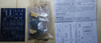
Let me start with the fact that a year ago I managed to buy this piece of shit, at least it didn’t cost a lot of money. Back then I didn’t really understand them and was taken in by their not bad characteristics.
4-channel power amplifier Power max. (4 ohms) 135 W x 4 channels / 450 W x 2 channels RMS power (4 ohms) 75 W x 4 channels / 240 W x 2 channels Frequency response: 15 Hz - 20 kHz Low pass filter: 30 Hz - 250 Hz Filter high frequencies: 150 Hz Low frequency level adjustment range: 0 - 12 dB Input sensitivity: 0.2 - 6 V Signal-to-noise ratio: > 90 dB Dimensions: 230 x 50.3 x 312 mm
The amplifier worked in a fairly gentle mode and never overloaded or overheated; a Supra SBD 300 Subwoofer
(by the way, still alive).
And now, two weeks later after the expiration of the warranty (12 months), this amp decided to go to another world and asked to be thrown into the trash can...
I will describe the symptoms of his illness:
1) at first the background was heard from one of the four channels 2) then the amplifier went into protection at half the gain, but did not heat up (the transistors were slightly warm, only the diode bridge was heated) 3) and then the amplifier began to go into protection at minimum volume with a frequency of two seconds (more precisely, to come out of it) 4) and then this shitty amplifier began, immediately after switching on, to go into protection and heat up like hell...
Perhaps after some time the symptoms could have changed (probably only for the worse), but I was just tired of riding in the trunk with a non-working sub and decided to see if anything could be done with this amp before going to buy a new one.
I didn’t find any information on repairing such amplifiers, but thinking that I couldn’t do anything worse, I went to disassemble this miracle, without showing any care or respect for the subject.
Car audio amplifier repair
Repairing a car audio amplifier - repairing a car amplifier for a person familiar with radio-electronic devices is not something difficult or impossible. In this article I want to share my experience in restoring the performance of failed UMZCH. It is clear that it is simply not realistic to cover all the moments that arise during practical repairs in this short selection. But still, if you adhere to certain actions, then in almost 100% of cases it is possible to repair this or that device in a short time. The basic principle when repairing an amplifier is to accurately identify the element in the circuit that has stopped working and thereby damaged the entire system.
DIY crafts for car enthusiasts
Recently, a friend asked me to repair a car amplifier that had been sitting in a repair shop for about a month, and as a result, the repairman asked for an exorbitant price of 2,500 rubles.
Amplifier Blaupunkt GTA-260 with a stated power of 400 watts. Actually a good two-channel amplifier, though about the power... lie
A sign of a malfunction is a short circuit between the positive and power ground, the fuse is intact. After opening it, the first thing I did was check the diode, it naturally rings in both directions, but there is no need to desolder it yet. In 90% of cases of such problems, power N-channel field switches are to blame, which are located in the input circuit and are designed to drive the power transformer; in this sample there were switches of the type IXTP64N055T, rated at 64 Amperes 55 Volts.
And the problem turned out to be them, both burned out. As a rule, in budget amplifiers of this type, where there is only one pair of switches in the inverter, I install IRF3205, but I only had irfz44 at hand, so I installed them. Naturally, their maximum current is slightly less, but by ear the difference in power will be imperceptible, taking into account the fact that the amplifier worked with wideband acoustics and not with a subwoofer.
I didn’t even understand why the repairman asked for such a sum for repairs and looked for a problem for about a month, a problem that can be identified without even opening the amplifier...
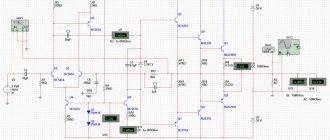
In general, this amplifier is built according to the standard topology - a push-pull inverter based on a TL494 PWM controller, a unit for high-speed discharge of the field gate capacitance based on two low-power complementary pairs, its own field switches, a transformer, an output rectifier with a filtering unit and a power amplifier. There are two channels here, they work in class AB, the power, purely from practice, I will say that no more than 100-120 watts per channel.
There is also a signal filtering unit for operating the amplifier with a subwoofer and pre-amplifiers, all of which are implemented on budget dual op-amps BA4558.
I am glad that there is a choke at the 12 Volt power input. For me the board is a bit of a mess, a bunch of jumpers, the components are crooked, if you are careful you can see some “balls” of solder, I never liked blaupunkts.
If anyone wants advice on choosing a car amplifier, I advise you to look towards alpine, I have repaired and studied many amplifiers - only alpine can boast of real quality both in sound and in the assembly and layout of the board, and in the end, for comparison, the board of my alpine mrv-f450.
I understand that from a price point of view it’s like heaven and earth, but it’s better to immediately take a good one - I assure you that the Alpine has never been repaired, I don’t remember how many years it’s been working without any complaints.
Author; AKA KASYAN
Popular;
How to choose a powerful speaker based on characteristics?
How to choose the right amplifier for a subwoofer? Which monoblock to choose?- How to repair or rewind a subwoofer
- DIY subwoofer speaker rewind
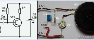
- DIY mini amplifier
- Car, two-channel audio amplifier
- A simple 120W amplifier for a subwoofer in a car
- Simple converter voltage 12 - 220 circuit
Troubleshooting before car amplifier repair
Before you start work, you need to find out what is broken. Only by determining which part caused the system to stop can it be restored. The electrical circuit will not work if there is no contact, the connection is not in the place where it is intended.
To detect a malfunction caused by a lack of sound, diagnostics begin with a frequency amplifier. To get acquainted with the circuit you will have to remove the cover. Using a magnifying glass, examine the components. If a capacitor or track is burnt out, the wiring does not hold, this is quite clearly visible. It also happens that the problem is not visible here.
power unit
Checking the audio frequency device should start with the power supply. Most units use simple transformer power supply circuits, and only some designs use pulse voltage converters. If the defect in the audio frequency system is unknown, then before checking, the power supply should be disconnected from the main circuit. This can be done by cutting the printed tracks. Testing the power supply begins with measuring the output DC voltage. If it is very high, you need to check the regulating transistor and zener diodes.
If there is no voltage, check the diode “bridge” and the presence of alternating voltage on the secondary winding of the power transformer. The tester should check the electrolytic capacitors of the filter. A bipolar power supply is checked in a similar way, since the electrical circuits at “+” and at “-” are usually the same. If there are faulty parts, they should be replaced and the presence of DC output voltage checked.
How to repair a car amplifier yourself
Having found the reason why the music does not turn on in the car, you can begin to eliminate the problem. When replacing a transistor that has broken down in a car amplifier, you must first check whether the fuse in the power supply is functioning and whether the diodes installed on the buses are working. If there are no problems with these elements, then the problem is in the transistor, and the solution is to replace it with a new one.
Having a special device in the form of an oscilloscope, repair work can be performed more efficiently. To do this, using the probes of the device, which are installed on the terminals present on the board, they check whether the signal is coming. If it is not there, you will have to install a new driver or replace the transistor elements.
Capacitors rarely fail. Therefore, they look for a breakdown here as a last resort. When installing the active elements, a mica gasket is made. To ensure good heat transfer, they can be lubricated with a special paste. Both transistors and the radiator are treated with the product. After completing the process, you must remember to close the amplifier.
Frequency settings
To set the desired frequency in the car amplifier, you need to know what parameters should be set, determine a more acceptable option and choose - without a subwoofer or with it:
- Decibel level – 0.
- The range of the front crossover is from 50, not more than 80;
- rear - up to 100.
- The position of the regulator is PH and, accordingly, LP.
How the acoustics will work depends on such data. They are responsible for the sound quality. After this, move on to the desired volume selection. Incorrectly set basic parameters will distort the sound.
Repair and restoration of imported amplifiers and receivers
It's no secret that modern budget-class audio equipment, mostly produced by unknown (no-name) Chinese manufacturers, is far from the Hi-Fi class and does not stand up to any criticism, not only in terms of stated characteristics, but also in terms of reliability and maintainability. In this regard, many lovers of high-quality sound prefer to maintain domestic equipment from the 80s and 90s in good condition, as well as repair or restore used imported equipment, which has poured in in a faulty state in recent years from abroad at very affordable prices. The article reveals some aspects of the repair of such devices (in the absence or unjustified high cost of the original elements) and allows trained readers to supplement their home collections with high-quality sound.
The material was prepared on the basis of practical experience gained during the repair of foreign-made amplifiers and receivers. In addition, when preparing the article, the author used materials from the forum of the MONITOR website [1].
Most malfunctions of amplifiers and receivers manifest themselves as a lack of signal at the output, or a transition to emergency operation after switching on or transferring from standby mode to operating mode. The main reason for this is the malfunction of the final cascades of devices made on transistors or in the form of hybrid integrated circuits (GICs).
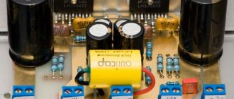
A separate topic in the Encyclopedia of the website “Monitor” [2] is devoted to the issues of ULF repair methods, which provides recommendations, diagrams and interesting practical examples on this issue. During the repair process, especially at night, it is very convenient to use the equivalent load for ULF, described in [3]. The version assembled by the author is shown in photo 1.
Let me briefly remind you of the main recommendations regarding the repair procedure itself and post-repair adjustment and control of devices.
When first turned on after repair (for push-pull UCHN):
- Install a powerful resistor with a resistance of about 100 Ohms (or a lamp) into the power gap to limit the current in case of incomplete elimination of the fault. It is allowed to use a lamp connected instead of a fuse in the circuit of the primary winding of the power transformer.
- It is recommended not to install output transistors before the first turn-on, but to limit yourself to the pre-output stage (taking into account the reduction in the maximum ULF power), and only then connect the output transistors.
- After each attempt to turn on the ULF, it is necessary to simultaneously discharge the electrolytic capacitors of the ULF power filters through a resistor with a resistance of about 50...100 Ohms.
Upon completion of the repair you must:
- Set the minimum possible voltage (on the order of units to tens of mV) at the output in the absence of an input signal, the so-called “0 V output”, if this adjustment is provided for in the circuitry.
- Set the quiescent current (if this adjustment is provided for in the circuit design) by setting the minimum voltage on the output transistors (B-E junction) to about 0.6 V for conventional and 0.9 V for cascades on composite transistors, or in the classical way - by measuring the voltage drop on the “current measuring » resistors of the output stage transistors with subsequent recalculation according to Ohm’s law, or direct measurement of the quiescent current in the open circuit. In this case, this should be done both with a cold and with a hot radiator - the current should not differ by more than two times, which indicates good thermal stabilization performance.
- Check the setting of the minimum quiescent current “by ear” and with an oscilloscope to ensure there is no step or distortion on the small signal.
- Use an oscilloscope to check the symmetry of the limitations on the standard load at the maximum possible power developed by the amplifier.
- Make sure that after repair the amplifier is able to provide the power stated in the data sheet.
- Look at the response of the ULF to rectangular pulses and a sinusoidal input signal, i.e. indirectly check the frequency response, lack of HF excitation, symmetry of half-wave limiting (on a sinusoidal signal), etc.
Let's move on to consider practical examples of malfunctions and ways to eliminate them.
Amplifier AKAI AM -2600
Right channel doesn't work
The AKAIAM-2600 amplifier arrived for repairs with the first channel completely burnt out. Output transistors 2SD426 (npn, 120 V, 12 A, 100 W, 5 MHz) and 2SB556 (pnp, 120 V, 12 A, 100 W, 6 MHz) in TO-3 packages (popularly called “boat”) were missing as in the ULF itself and on sale. The output stage supply voltage is bipolar ± 50 V.
Having a sufficient supply of KT818G and KT819G transistors, it was inappropriate to buy imported analogues. Using a device similar in functionality to the devices described in [4-6], specimens with Uke of the order of 250 V (with 100 V specified in the specifications) were selected, i.e. The safe operating area (OSR) for this parameter was covered more than twice (and this was by post-Soviet components in the output stage). It should be noted that a sufficient number of transistors did not meet the specifications for this parameter, i.e. had Uke of about 80 V, there were even instances with a value of 40 V. The remaining faulty transistors were replaced with their imported analogues, after which the operation of the amplifier was restored.
Amplifier Sanusi A-700
The amplifier does not turn on.
Received for repair after attempts at unqualified repairs in the condition shown in photo 2 . The cause of the malfunction is the inoperability of one of the GIS channels of the STK4893 type (it had already been changed previously - see photo 2 ). This microcircuit was not on sale (discontinued). Having information from forums about their widespread counterfeits (defects), it was decided to “open” the one installed in the amplifier. The method of non-destructive “opening” of such GIS is given below.
Since the SanusiA-700 amplifier circuit is not available on the Internet, to restore the GIS it is recommended to download its original “datasheet” from the manufacturer, which shows the internal circuit of the microcircuit ( Fig. 1 ). By checking the elements in this GIS, a number of faulty SMD components were identified ( Fig. 1 ). Fig . 2 shows the marking of faulty SMD components of the STK4893 GIS, and Fig. 3 – their location on the chip substrate.
For repairs, you can use both SMD transistors in the SOT23 package and ordinary ones in the TO-92 package, but please note that they have two types of pinouts.
The faulty output transistor was replaced by KT819G, selected using the device mentioned above (for the installed instance, Uke was 230V). It is possible to use imported transistors such as TP41, MJE3055 and the like. This transistor is installed outside the GIS on the radiator.
Photo 3 and photo 4 show the appearance of the restored GIS and the placement of the external output transistor on the amplifier heatsink. In a similar way, you can restore other GIS from this “line”, which will be discussed below.
For information, the STK4893 GIS power supply in this ULF is bipolar ±50 V, obtained after rectifying 2 alternating voltages of 35 V each, which come from the secondary windings of the transformer.
Amplifier Siemens RE 666
The amplifier does not turn on.
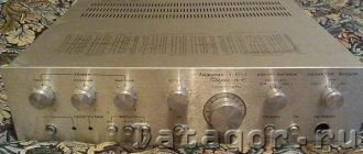
This amplifier with a preamplifier and tuner, better known to audio lovers under the name “Devil's Troika” ( photo 5 ), was purchased by the author for personal use with a faulty GIS STK-0049. Looking ahead - in the first there was simply a breakdown of the output transistors, both external “current measuring” resistors of 0.33 Ohm and an overheated 2.2 kOhm resistor on the ULF printed circuit board were broken, in the second GIS there was a break in one of the output transistors.
The amplifier has never been repaired; it contains original STK-0049, which are impossible to find today (of normal quality and at an affordable price).
After desoldering the GIS, they were “opened”, for which, turning them over with the substrate facing them, they were uniformly heated for about a minute with an ordinary construction hairdryer at the first division for about a minute, after which a scalpel (placed with pressure vertically on the side of the end of the aluminum substrate between it and the body of material resembling carbolite) the edge of the substrate will do (preferably on both sides). Then it is carefully separated from the body. It is advisable to warm it up especially well in the area of the end with the GIS leads.
They are monolithically filled with body material. Support for the pins is required, otherwise they may lag behind the substrate. At first this happened with one pin, but, however, it is easily soldered into place.
After this, the tester checks the serviceability of the elements in the GIS (see Fig. 4 from the “datasheet” and a diagram drawn directly from the GIS itself - Fig. 5 ). Only the output transistors were damaged (the terminals of the bases and emitters of these transistors are easily removed with side cutters), connected with pre-output ones according to the Darlington circuit (hence the name of these GIS - DARLINGTON POWERPACK), and some thick-film resistors ( photo 6 ) . The material of the conductors in the GIS (nickel or chromium coating) can be easily stripped to copper and tinned. New resistors instead of damaged ones are installed inside the GIS. To connect the base pins of external transistors, it is convenient to solder them to the unused 4, 5, 6 or 7 GIS pins. Pins 4 and 7 were used. In photo 6 , this is done with conductors in light insulation. During the repair, np-n transistors of the KT8101A type in one GIS and KT819G1 in the other, which were available, were used as output transistors in the quasi-complementary output stage. Installation of imported transistors in these GIS is encouraged. The transistors are secured through insulating heat-conducting gaskets on a standard ULF radiator ( photo 7 ).
In the process of repairing and studying the information available on the Internet and directly the “datasheet” on STK-0049, it turned out that, if necessary, to restore or assemble an external analog printed circuit board (this is exactly what was planned to be done initially), the composite transistor TR2 ( Fig. 5 ) can replace with 2SD894, 2SD946, or 2SD947 2SC1881, and the pre-output complementary pairs of transistors TR3/TR4 with 2SD600/2SB631, 2SC4793/2SA1837 or KT815G/KT814G.
For information, the power supply for the output stages of the STK-0049 GIS in the bottom ULF is bipolar ±35 V, obtained after rectifying two 28 V alternating voltages coming from the secondary windings of the transformer.
A few words about the Siemens RP666 preamplifier. In it, as well as in the final ULF, during the repair, a number of faulty filtering and separating electrolytic capacitors with greatly increased ESR were replaced, and a complete preventive maintenance was carried out - cleaning of the variable resistors of the regulators (which will be discussed later). The refurbished amplifier sounds really great.
Amplifier FISHER CA-9030
The amplifier is stuck. According to the client, he “simply cleaned the inside of it from dust by himself,” after which, after turning it on, the power indicator lights up, but there is no response to the buttons on the front panel.
The manual for the amplifier is available on the MONITOR forum [7]. A direct check from a separate power source (+5 V) of the control board showed that everything is normal - there is a response to key presses, the control is fully operational. “Bus resistance” is checked by the tester in ohmmeter mode and allows for a quick assessment of indirect diagnostics of the serviceability of the IC, especially in cases with suspected “lightning apparatus” and “after exposure to static electricity”. For CE, DATA, CLK per case (“mass” of the ULF) it was about 23...45 LM. A separate check of the disconnected circuits of the LC7821 switch, where these signals are received, showed that it is working.
A subsequent re-check of the processor buses and ports revealed that some of them were almost completely short-circuited to ground. Having discharged capacitor C709 (2200.0 µF x 10 V) in the RESET power generation circuit ( Fig. 6 ) by shorting it with tweezers and powering the board again from an external power supply, everything returned to normal. Having assembled the amplifier, before turning it on, I discharged the specified capacitor again (a technological cutout must be made in the metal screen of the control board above it) - the ULF was fully operational. Apparently under the influence of “static electricity,” which could be perceived by him as a “protect” signal, the processor ports “latched” into a state closed to ground and maintained this state for a very long time due to the low self-discharge current of capacitor C709. This example well illustrates possible errors in diagnosing a processor malfunction, as well as the approach to the method of testing it.
The author reminds that one hundred available methods, diagrams and other information on the devices mentioned in the article can be found in the public domain on the forum of the MONITOR website [1].
Literature
- https://monitor.net.ru/forum/index.php - forum on the MONITOR website.
- https://monitor.net.ru/forum/viewtopic.php/t=55066 – topic “Woof Amplifiers – Repair Technology”.
- Butov A.L. Equivalent load of the day ULF // Radioamator. – 2009. – No. 1. – P. 3, 4.
- Zyzyuk A.G. Portable version of the Uec meter // Radioamator-Electric. – 2002. – No. 8. – P. 8-10.
- Zyzyuk A.G. Selection of transistors for powerful UMZCH // Radioamator. –2001. – No. 6. – P. 6, 7.
- Butov A.L. Device for testing high-voltage transistors // Radio. – 2003 – No. 3. P.22.
- "Manual" for the FISHERCA-9030 amplifier. – https://minotor.net.ru/forum/fisher-ca-9030-download-23691.html.
Author: Ruslan Kornienko, Kharkov
Source: Radioamator No. 4, 2014
Amplifier path
The next step is to check the output stage. A common malfunction is the breakdown of power terminal transistors. If the device fails during operation, you need to touch the housings or heatsinks of the output semiconductor devices with your finger. Strong heating of the radiator indicates that the transistor is broken. Using the tester, you can easily check the base-emitter and base-collector junctions. If there is any doubt, it is better to remove the transistors from the board. In order to properly repair an audio amplifier, one tester is not enough. To work you will need a low frequency generator and an oscilloscope.
Functionality check
Repair of car amplifiers first begins with ULF diagnostics:
- First you need to open the case and carefully inspect the circuit, use a magnifying glass if necessary. During diagnostics, you may notice damaged components of the circuit: resistors, capacitors, broken conductors or burnt out board tracks. But if you find a burnt-out component, you need to take into account that its failure may be a consequence of the burnout of another element, which in appearance may seem intact.
- Next, diagnose the power supply, in particular, check the output voltage. If burnt out resistors are identified, these elements will need to be replaced.
- Apply power to the ULF and the Remout output, then you need to short-circuit the system to positive and look at the PROTECTION diode indicator. If the light comes on, this indicates that the device has been protected. The reason may be poor power or its absence on the board, a broken transistor, or problems with the operation of the voltage converter. In some cases, the reason lies in the breakdown of the transistor power amplifier for one of several channels.
- If, after power has been applied, the fuse element does not burn out, you need to check the voltage level at the output. It should be approximately 2x20 in or more.
- Carefully inspect the transformer device of the voltage converter; it may have burnt out turns or broken circuits. Smell this element, it may smell burnt. In some ULF models, a diode assembly is installed between the PN output and the amplifier - if it fails, the assembly can also include protection.
Soldering iron on an amplifier chip