Today we have a useful homemade product for connoisseurs of good sound: a high-quality tube amplifier made by yourself
Hello!
I decided to assemble a push-pull tube amplifier (my hands were really itching) from the parts I had accumulated over a long time: housing, lamps, sockets for them, transformers, etc.
I must say that I got all this stuff for nothing (free of charge), and the cost of my new project will be 0.00 hryvnia, and if I need to buy something in addition, I’ll buy it for rubles (since I started my project in Ukraine, and I’ll finish already in Russia).
I'll start the description with the body.
Once upon a time it was, apparently, a good amplifier from SANYO model DCA 411.
But I didn’t have a chance to listen to it because I got it in a terribly dirty and non-working state, it was dug up beyond repair and the burnt 110 V power supply (Japanese, probably) smoked all the insides. Instead of the original final stage microcircuits, there are some snot from Soviet transistors (this is a photo from the Internet of a good example). In short, I gutted it all out and began to think. So, I couldn’t think of anything better than stuffing a lamp there (there’s quite a lot of space there).
Decision is made . Now we need to decide on the scheme and details. I have a sufficient number of 6p3s and 6n9s lamps.
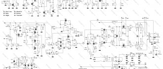
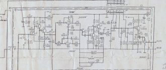
Due to the fact that I had already assembled a single-cycle amplifier for 6p3s, I wanted more power and, having rummaged through the Internet, I chose this push-pull amplifier circuit for 6p3s.
PP Push-Pull Tube Amplifiers PP is short for Push-Pull.
- 2.5W. Class B triode amplifier using 6N6P, 6N2P tubes.
- 3.5W. Tube amplifier for 6N6P, 6F1P.
- 7.5W. Push-pull amplifier based on a 6N9S tube.
- 6W. A simple push-pull tube amplifier for 6P14P.
- 6W. Push-pull class A amplifier using 6P6S tubes.
- 10W. Push-pull amplifier on 6F3P.
- 12W. Tube ULF with ultra-linear final stage on 6P14P.
- 12W. Ultralinear tube amplifier for 6P14P, 6N2P.
- 15W. Push-pull ULF on 6P3S, EL34.
- 16W. Miniature ULF on 6P36S.
- 20W. Push-pull tube amplifier based on 6P36S.
- 20W. Push-pull amplifier based on 6P36S and 6N1P tubes.
- 22W. Ultralinear push-pull amplifier based on 6P3S and 6N8P tubes.
- 25W. Push-pull tube amplifier on GU-50
- 80W. Ultralinear push-pull ULF on four 6P3S and 6N8P lamps.
- 200…400W. Powerful push-pull amplifier using 6P3S or 6P45S tubes.
- Push-pull amplifier on 6С4С.
- Entry-level push-pull tube amplifier for 6P18P, 6P43P
- Push-pull ULF channel on 6P45S lamps
- Ultralinear amplifier for 6P14P, 6N1P with microphone input.
Entry-level tube UMZCH
Over the years, sound amplification technology has accumulated a huge number of technical solutions that make it possible to obtain excellent results, but despite everything, many designers (not only radio amateurs, but also serious companies) again and again return to the roots - as simple as possible from the point of view of circuit design, but at the same time At the same time, the most effective solutions that allow you to get high-quality sound. One of these areas of design is the construction of UMZCH using vacuum tubes.
UMZCH - Audio Frequency Power Amplifier
However, we must pay tribute here too - despite the apparent simplicity of the electrical circuits, not everyone manages to get a “decent” sound. But if for an experienced radio amateur failure will bring only one more coin to his treasury of experience, then for a beginner this problem, being insoluble by his own efforts, can deprive him of the desire to engage in design for a long time. However, this is already from the field of psychology...
Beginner designers are offered a very easy to repeat, and most importantly, not capricious and fairly high-quality tube UMZCH, which uses common lamps and parts that were widely used in televisions and radios at one time.
The amplifier was designed as a final amplifier (i.e., it does not include tone controls or any other components, such as switches, correction preamplifiers, etc.) and was originally intended to amplify the signal coming from the computer sound card, however, very good (subjectively) characteristics allow it to be used to amplify signals from other, more “serious” sources (CD player, vinyl disc player, tape recorder, etc.)
The schematic diagram of one amplifier channel is shown in Fig. 1
Two-stage amplifier. The first stage is built on one half of the 6N3P double triode (VL1) and is a classic voltage amplifier stage. The second half of the tube is used in the second channel of the amplifier.
Lamp pinout 6N3P
On resistors R4, R5, thanks to the cathode current flowing through them, a bias voltage is created, which sets the operating mode of the lamp. The absence of a capacitor in the cathode circuit (which is usually present in industrial designs and is connected in parallel with the cathode resistor) is not without meaning - this makes it possible to obtain local feedback in the cascade, due to which, although the gain is slightly reduced, the linearity of the cascade is increased. The depth of such local negative feedback is small and is determined by the ratio of the resistance values of resistors R4 and R6. This technique also allows you to “kill” the second bird - it is very convenient to supply a common OOS voltage to the cathode circuit, which is what was done in our case - the signal from the output of the amplifier through a divider formed by resistors R5 and R4 is supplied directly to the cathode.
The type of lamp and the operating point were chosen based on the desire to obtain a mode in the linear section of the current-voltage characteristic (volt-ampere characteristic) of the lamp, while the appearance of grid current would be unacceptable (the current in the grid circuit occurs when the voltage on it becomes positive relative to the cathode, as a result, strong signal distortion occurs) in any operating mode of the amplifier, and a small output impedance of the cascade with sufficient amplification, which will allow you to “ignore” the parasitic capacitances of the mounting and the lamp, and the inductance of the resistors of the subsequent cascade. But with all this, the anode current must be small enough to ensure the longevity of the lamp. As a result, a resistance in the anode circuit of 47 kOhm and an anode current of 3 mA were selected (with the anode current regulated by the reference book being 8 mA for a 6N3P lamp) - at this point the I-V characteristics are quite linear for an input signal with a swing of up to 3 volts. The voltage gain of the cascade is 16.5.
The second stage is also not original - it is a typical single-ended stage, built on a powerful 6P14P (VL2) output pentode. Cathode resistor R9 sets the operating point of the lamp (anode current 48 mA, second grid current 7 mA), and also organizes local shallow OOS. The resistor in the grid circuit is chosen to have a relatively small resistance to reduce the influence of parasitic mounting capacitances and the leakage current of the first grid (lamps in general always have a leakage current in the first grid circuit, even when the voltage on it is negative relative to the cathode, but it is most noticeable for high-power lamps. The magnitude of this current is of the order of several µA. The negative effect is the “departure” of the lamp mode), but it is important that its resistance is significantly greater than the output resistance of the previous stage.
The lamp of the second stage is loaded onto the output transformer - it is necessary to match the high output resistance of the lamp (about 4.5 kOhm) with a relatively low-impedance load. The principle of choosing a transformer for this design is “cheap and cheerful” - transformers of the TVZ-1-9 type were used, which were used both in televisions and in some radios. Other types of output audio transformers can be used, it is only important that they are designed specifically for use in single-ended output stages. You can even experiment with TVK-type transformers (used in vertical scanning output stages), but you must be aware that the output transformer is perhaps the most important part in a tube amplifier - its quality, for the most part, will determine the quality of the amplifier as a whole.
Output stage voltage gain 0.85 (measured at 4 ohm load)
A filter is applied at the amplifier input that does not allow low frequencies of the audio range to pass through to the amplifier input (from approximately 40 Hz and below). The need for such a filter is caused by the following considerations: a) most middle-class household speaker systems have lower operating frequencies from 40 to 60 Hz and, in principle, are not capable of reproducing a signal with a frequency below this threshold - supplying a signal to the speaker system that is obviously lower than its minimum operating frequency is only generates significant additional distortion due to the displacement of speaker diffusers by this signal; b) domestic premises are small in size and, as a result, at low frequencies in such rooms there are many resonances that cause a “booming” effect during playback, and the smaller the room, the more pronounced this effect is, the higher the resonance appears at higher frequencies; c) as the frequency decreases, the amplifier power required for playback must increase (this is true for the entire frequency range) - for example, if 3 W is enough to play a signal with a normal volume of 100 Hz, then to play 50 Hz with the same volume you need more 12 W amplifier output power; d) the lower operating frequency of most industrial audio transformers is 40-50 Hz - at lower frequencies the transformer, as well as the acoustic system, loses efficiency (this occurs due to the finite value of the inductance of the primary winding), and in combination with the higher power of the lower frequency the signal also generates significant distortion. Taking into account all this, as well as the fact that the output power of the single-ended amplifier stage on the 6P14P lamp is limited to 4.5 W, it was decided to use such a filter. Of course, if you use high-quality transformers and acoustic systems, then there is no need for such a filter. In this case, you can not mount it by removing R2 and replacing C2 with a jumper.
Looking ahead, I would like to note that when comparing the sound of an amplifier with and without a filter, subjective preference was always given to the version of the amplifier with a filter - the bass, contrary to predictions, is more “elastic” due to the elimination of overload of the output stage and a significant reduction in the “mumbling” of the room.
power supply is quite simple - it is a transformer, also taken from an old tube TV, with an anode voltage rectifier (Fig. 2). The capacitance of filter capacitor C7 was chosen to be relatively small - this is caused by the desire to reduce the peak current through the rectifier diodes (it is no secret that the diodes of a rectifier operating on a capacitive load are open only for a short period of time compared to the half-cycle duration, and at this time current flows through them , significantly exceeding the average consumed by the load). But since voltage ripples are quite significant in a small capacitance, the amplifier (Fig. 1) uses a filter R10 C5, where the capacitance C5 can already be quite large in order to effectively suppress them. The first stage is also powered through the same filter R7 C3, which additionally protects it from supply voltage ripples caused by the operation of the second stage.
Chain R11-R14 (Fig. 1) is common to both channels of the amplifier and is designed to create a positive potential of the filament circuit relative to the cathodes of the lamps. This is necessary to reduce the background of alternating current - a highly heated filament and cathode form some semblance of a vacuum diode, and if there is a positive voltage on the cathode relative to the filament at some points in time, a small current will flow from the filament to the cathode. This current will also flow through the cathode resistors, causing a voltage drop across them, which will then be amplified by all subsequent stages in the same way as the useful signal.
R11 and R12 connected in series perform another function - through them the capacitances of the power filters are discharged when the amplifier is turned off.
The total current consumed by the filament lamps is 1.85 A. The filament winding of the transformer must be designed for this (or greater) current, otherwise overheating of the filament winding of the transformer may occur.
Construction and details . Both channels of the amplifier, except for the power supply, are entirely mounted on one printed circuit board (
). Since lamps dissipate quite a lot of heat, there is no point in trying to achieve a high installation density. For the same reason, it is advisable to use foiled fiberglass laminate as a material for a printed circuit board - this material is more temperature resistant than textolite or getinax, and does not deform when heated, which often happens with boards based on getinax.
Resistors can be BC or MLT types. R1-R5, R13 and R14 can be of any power (the printed circuit board is designed to install resistors such as BC-0.5 and MLT-0.5), R6, R7, R8, R11 and R12 are best taken with a power of at least 0.5 W (for R7 and R8 this is due not so much to the power dissipated on them, but to the possibility of “shooting through” between the threaded turns at the moment of power supply to the amplifier). R9 must have a power of at least 1 W, R10 - 2 W. It is best to take a wire R10 - also because of a possible breakdown at the moment of switching on, but in extreme cases, MLT-2 will also do.
The resistances of resistors R1, R11-R14 can differ significantly from those indicated in the diagram: R1 can be from 100 kOhm to 1 MOhm; R13, R14 from 1 to 100 kOhm, but preferably the same resistance; resistance R11 can vary from 100 to 470 kOhm, and resistance R12 should be 5-15 times less than resistance R11. R7 can be from 2 to 8.2 kOhm. Resistance R10 should not be increased, but any resistors in the range from 100 to 220 Ohms can be used. The resistance of R6 can also vary - from 22 to 75 kOhm, however, it must be taken into account that when increasing the resistance of R6, it is necessary to increase the resistance of R4, as a result of which the depth of the feedback will slightly change, and therefore the sensitivity of the amplifier will change. To set the required sensitivity, you will need to select resistance R5. Resistance R9 should not be changed - only as a last resort you can install a resistor with a resistance of 130 Ohms.
The printed circuit board has two places for resistor R12 (indicated in the wiring diagram as R12″), connected in parallel, so two resistors with a resistance greater than the nominal one can be used as R12.
It doesn’t hurt to select resistors R4, R5 and R9 for both channels in pairs with the closest resistance values - this will make it easier to configure the amplifier.
Capacitors C1, C2 and C4 are film. C1 and C2 type K73-9, C4 - K73-17. Capacitance C4 can be from 0.47 to 1.5 µF. The operating voltage of capacitors C1 and C2 is not critical (capacitors with a voltage of 100 V are used), the voltage of capacitor C4 must be at least 250 V. Other types of capacitors can be used, but it must be taken into account that, for example, metal-paper or mica capacitors will have much larger dimensions, and the use of ferroelectric capacitors in audio circuits is unacceptable due to the significant piezoelectric effect. The use of unsealed capacitors (type BMT, MBM) is also unacceptable due to the presence of leakage currents in them. Electrolytic capacitors are absolutely not suitable.
Power filter capacitors - any electrolytic capacitors of suitable size with an operating voltage of at least 300 V. Capacitance C3 must be at least 10 µF (however, in this case it is advisable to increase the resistance R7 to 5.1-6.2 kOhm), it is not advisable to reduce capacitance C5 ( in extreme cases, you can set 220 uF). It is also undesirable to reduce the capacitance of filter capacitor C7 in the power supply.
The diodes of the rectifier bridge can also be replaced with any others, it is only important that when the amplifier is turned on, they can withstand the charging current of the filter capacitors (up to 2 A), and are designed for a reverse voltage of at least 400 V. The D226G is quite suitable.
Socket PL9-2 Socket PLK9
Modified PLC9 socket
To place the lamps, sockets of the PL9-2 type were used. Other sockets that can be installed on a printed circuit board are also suitable. If these are not available, you can use sockets that are not suitable for printed circuit mounting. To install them on the board, you can solder pieces of thick single-core wire to their terminals, with the help of which the socket will be installed on the board. However, it would be preferable to modify the socket terminals directly by biting off part of the terminal with sharp side cutters (nippers) (see photo).
JP1 jumpers are used from failed computer motherboards. The pins of the connector through which the signal is supplied to the amplifier input are of the same type. To connect the output transformer and power supply, pins are also mounted on the board - they are used from standardized connectors used in TVs. The wires to these pins are soldered, although the use of connectors is also possible.
During installation, special attention should be paid to connecting to the common wire - all circuits of the common wire must be connected either at one point or in a strictly defined sequence. This sequence is observed on the printed circuit board - you just need to make sure that there are no “extra” connections.
The rated output power of the amplifier is 3 W, maximum 4 W, rated input voltage 0.75 V. This power is quite enough for comfortable listening to audio programs in a room of 30 m2 (using 6AC-224 speaker systems, from the “Cantata-205” radio set) .
The appearance of the amplifier mounted on the board is shown in the photograph.
Setting up the amplifier is not difficult. First of all, make sure that the power supply is working. The '+275' voltage can range from 250 to 300 V (depending on the type of transformer used). An alternating voltage of 6.3 V is considered within normal limits if it is not lower than 6.0 V, but not higher than 6.5 V. Then the amplifier board is connected to the power supply. We are not installing lamps yet.
| Table 1 - voltages on sockets without lamps | ||||||||||||||||||||||||||||||
Lamp socket
|
After connecting the board, you need to check the incoming voltage to the lamp sockets. Table 1 shows the voltage values for this case.
Be very careful when measuring the voltage on the 2nd blade of the VL2 socket - there should be an absolute '0' there. The slightest positive DC voltage will mean only one thing - capacitor C4 has a leak and must be replaced before the lamps are turned on. The voltage '+49' is the voltage that is obtained at the divider R11-R12, and if you changed the values of these resistors, then it may differ from the specified one, but in any case it should correspond to the voltage at the connection point R11-R14. The absence or significant discrepancy in voltage '+275' on any leg indicates a malfunction in this circuit, usually a break. Of course, C3 or C5 may still be faulty, but in this case the effect of their failure will be expressed by charring resistors R7 or R10, respectively.
| Table 2 - voltages on lamp legs | ||||||||||||||||||||||||||||||
Lamp socket
|
If everything is in order, turn off the power, connect the speakers or equivalent load (which can be a resistor with a resistance of 3.9 to 8.2 Ohms and a power dissipation of at least 2 W), remove jumper JP1 and install the lamps. We supply power to the amplifier and immediately control the voltages on the legs of the 3 VL2 lamps again. As the cathodes heat up, it should smoothly increase to +6.0..6.1 V and then remain there - this will indicate that the lamps have reached normal operating mode. A voltage higher than 6.3 V indicates severe wear of the lamp (the slope of the characteristic has decreased, usually a consequence of gas contamination inside the lamp cylinder), a low voltage (from about 5.8 and below) is also typical for lamps that have been operating for a long time (loss of emission) - Such lamps must be replaced. The voltages on the other legs of the lamps are shown in Table 2. The voltages on the anodes and cathodes of VL1 are indicated for the case of open JP1 - when it is installed in place, the voltages on the anodes will drop to 110..120 volts, and on the cathodes to 1.7..1.8 IN.
If the voltages are within the permitted limits, you can try to apply a small amplitude signal to the amplifier input (about 25-50 mV, since JP1 is removed and the sensitivity is maximum). If successful, all that remains is to make sure that the overall feedback is negative. To do this, carefully install JP1 in place. If in this case self-excitation of the amplifier occurs, accompanied by loud noise, howling or whistling in the speaker system, in this case it is necessary to swap the ends of the secondary winding of the output transformer with each other.
At this point, the adjustment can be considered complete.
Precautionary measures . 1. During any installation work, the device must be de-energized. Since the amplifier uses large-capacity storage capacitors, it is necessary to wait until they are discharged, which occurs within 30-40 seconds after the amplifier is turned off. When testing the power supply separately from the amplifier, be careful - in this case, capacitor C7 can store charge for a very long time (up to several days). To ensure the discharge of the capacitor, a resistor with a resistance of 100 kOhm to 1 MOhm and a power of at least 0.5 W should be temporarily soldered in parallel to it. It is strictly not recommended to discharge capacitors by short-circuiting their terminals (for example, with a screwdriver or tweezers) - this can lead to both failure of the capacitor and injury.
2. Tube amplifiers, unlike transistor amplifiers, are not afraid of a short circuit in the load, but a break in the load circuit can damage the output transformer. It is highly not recommended to turn on the amplifier without a rated load connected to its output (nominal load resistance 4...8 Ohms) - this risks breakdown of the insulation of the primary winding of the output transformer due to its significant inductance. If you are going to use the amplifier together with headphones, you need to take this into account and, while connecting the headphones, provide a parallel connection of an equivalent load, which can be a regular resistor with a resistance of 3.9 to 8.2 Ohms and a power dissipation of at least 2 W. Any load switching, during which even a short-term break in its circuit is possible, must be performed only with the amplifier power turned off.
3. The 6P14P output pentodes are very hot during operation. Don't get burned
Literature: 1. D.S. Gurlev. Handbook of electronic devices. - “Technology”, Kyiv, 1966 2. M. Kireev. Amateur Radio High-End. 40 best designs of lamp UMZCH for 40 years. “Radioamator”, Kyiv, 1999
List of radioelements
| Designation | Type | Denomination | Quantity | Note | Shop | My notepad |
| Amplifier circuit | ||||||
| VL1 | Vacuum tube | 6N3P | 1 | Search in the Otron store | To notepad | |
| VL2 | Vacuum tube | 6P14P | 1 | Search in the Otron store | To notepad | |
| C1 | Capacitor | 0.068 µF | 1 | Film K73-9 | Search in the Otron store | To notepad |
| C2 | Capacitor | 0.027 µF | 1 | Film K73-9 | Search in the Otron store | To notepad |
| C3 | Electrolytic capacitor | 22 µF 350 V | 1 | Search in the Otron store | To notepad | |
| C4 | Capacitor | 1 µF | 1 | Film K73-17 | Search in the Otron store | To notepad |
| C5 | Electrolytic capacitor | 330 µF 350 V | 1 | Search in the Otron store | To notepad | |
| C6 | Capacitor | 0.1 µF | 1 | Search in the Otron store | To notepad | |
| R1 | Resistor | 390 kOhm | 1 | Search in the Otron store | To notepad | |
| R2 | Resistor | 82 kOhm | 1 | 0.5 W | Search in the Otron store | To notepad |
| R3 | Resistor | 220 kOhm | 1 | Search in the Otron store | To notepad | |
| R4 | Resistor | 750 Ohm | 1 | Search in the Otron store | To notepad | |
| R5 | Resistor | 2.7 kOhm | 1 | Selection | Search in the Otron store | To notepad |
| R6 | Resistor | 47 kOhm | 1 | Search in the Otron store | To notepad | |
| R7 | Resistor | 3.3 kOhm | 1 | Search in the Otron store | To notepad | |
| R8 | Resistor | 150 kOhm | 1 | Search in the Otron store | To notepad | |
| R9 | Resistor | 120 Ohm | 1 | 1 W | Search in the Otron store | To notepad |
| R10 | Resistor | 220 Ohm | 1 | 2 W | Search in the Otron store | To notepad |
| R11 | Resistor | 100 kOhm | 1 | Search in the Otron store | To notepad | |
| R12 | Resistor | 22 kOhm | 1 | Search in the Otron store | To notepad | |
| R13, R14 | Resistor | 10 kOhm | 2 | Search in the Otron store | To notepad | |
| TR1 | Transformer | TVZ-1-9 | 1 | Search in the Otron store | To notepad | |
| Jumper | 1 | Search in the Otron store | To notepad | |||
| Power supply diagram | ||||||
| VD1-VD4 | Diode | D237B | 4 | D226G | Search in the Otron store | To notepad |
| C7 | Electrolytic capacitor | 22 µF 350 V | 1 | Search in the Otron store | To notepad | |
| FU1 | Fuse | 2 A | 1 | Search in the Otron store | To notepad | |
| TR2 | Transformer | 1 | see diagram | Search in the Otron store | To notepad | |
| SW1 | Switch | 1 | Search in the Otron store | To notepad | ||
| Add all | ||||||
Tags:
- ULF
↑ Input selector
I organized an input selector on three TAKAMISAWA relays (according to the number of inputs), which switch a low-current signal. I didn’t make a printed circuit board for the switch; I assembled everything on a breadboard.
The scheme is something like this:
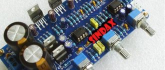
For the sake of beauty, I installed dial indicators. The indicators are controlled by the domestic K157DA1 microcircuit. The circuit has been converted to single-pole power supply, a printed circuit board is included.
The switch, K157DA1 microcircuit and indicator backlight diodes are powered from a single stabilized voltage source.
ULF on KT88 - assembly and setup
To assemble the kit, you only need to have basic soldering skills, and the whole job will take several evenings. The kit contains many parts, but following the instructions will ensure successful results. Before you start installing the equipment, you need to study the circuit diagram so that it is imprinted in your memory - it will be easier to assemble it, knowing approximately what goes where.
Power supply and adjustment of the balance between the output stage lamps. This is done using a multimeter, which is inserted at the test points on the top of the amplifier and then adjusted with a 25 ohm potentiometer. After an hour of work, you should check the balance again. I had a discrepancy of only a few milliamps over a month of daily use.
After balancing the offset, I connected the Fostex FE206E acoustics (96 dB / 1 W) and checked for hum. Everything is fine. For the PSU, I was hoping to get about a 60 second power-up delay, but couldn't get more than about 30 seconds.
The radiator for the LM317 was quite hot - about 100 C (the maximum operating temperature of the LM317HVT is 125 C). The temperatures of the power transformer and audio output were 65 C to 45 C respectively.
↑ Electronic throttle
Instead of conventional chokes, I used an “electronic throttle” assembled according to this scheme:
I note that the actual voltage drop across the inductor is about 20-25 V. Take this into account in your design! The inductor circuit board is also included.
Notes
Standard range of metal drill diameters (mm)
1, 1.5, 2, 2.5, 3, 3.3, 3.5, 4, 4.1, 4.2, 4.5, 5.0, 5.5, 6, 6.5, 7, 7.5, 8, 8.5, 9, 9.5, 10, 10.5, 11, 12, 12.5, 13
How to read inch screw sizes
For example: #4–40 1/4″.
The first digit is the number corresponding to the diameter of the screw (diameter = “#” x 0.013″ + 0.060″). The second number is the thread pitch (number of threads per inch): 25.4 / 40 turns = 0.635. The third number is the length of the screw: 1/4″ = 6.35 mm.
Some correspondence between the screw number and its diameter are shown in the table.
| Screw no. | diameter (inch) | diameter (mm) |
| #0 | 0.0600″ | 1.5240 mm |
| #1 | 0.0730″ | 1.8542 mm |
| #2 | 0.0860″ | 2.1844 mm |
| #3 | 0.0990″ | 2.5146 mm |
| #4 | 0.1120″ | 2.8448 mm |
| #5 | 0.1250″ | 3.1750 mm |
| #6 | 0.1380″ | 3.5052 mm |
| #8 | 0.1640″ | 4.1656 mm |
| #10 | 0.1900″ | 4.8260 mm |
| #12 | 0.2160″ | 5.4864 mm |
Table 1.
Some correspondence between the screw number and its diameter
Correspondence between American and European wire diameter records
| American Wire Gauge (AWG) | Diameter (inches) | Diameter (mm) | Sectional area (mm2) |
| 0000 | 0.46 | 11.68 | 107.16 |
| 000 | 0.4096 | 10.40 | 84.97 |
| 00 | 0.3648 | 9.27 | 67.40 |
| 0 | 0.3249 | 8.25 | 53.46 |
| 1 | 0.2893 | 7.35 | 42.39 |
| 2 | 0.2576 | 6.54 | 33.61 |
| 3 | 0.2294 | 5.83 | 26.65 |
| 4 | 0.2043 | 5.19 | 21.14 |
| 5 | 0.1819 | 4.62 | 16.76 |
| 6 | 0.162 | 4.11 | 13.29 |
| 7 | 0.1443 | 3.67 | 10.55 |
| 8 | 0.1285 | 3.26 | 8.36 |
| 9 | 0.1144 | 2.91 | 6.63 |
| 10 | 0.1019 | 2.59 | 5.26 |
| 11 | 0.0907 | 2.30 | 4.17 |
| 12 | 0.0808 | 2.05 | 3.31 |
| 13 | 0.072 | 1.83 | 2.63 |
| 14 | 0.0641 | 1.63 | 2.08 |
| 15 | 0.0571 | 1.45 | 1.65 |
| 16 | 0.0508 | 1.29 | 1.31 |
| 17 | 0.0453 | 1.15 | 1.04 |
| 18 | 0.0403 | 1.02 | 0.82 |
| 19 | 0.0359 | 0.91 | 0.65 |
| 20 | 0.032 | 0.81 | 0.52 |
| 21 | 0.0285 | 0.72 | 0.41 |
| 22 | 0.0254 | 0.65 | 0.33 |
| 23 | 0.0226 | 0.57 | 0.26 |
| 24 | 0.0201 | 0.51 | 0.20 |
| 25 | 0.0179 | 0.45 | 0.16 |
| 26 | 0.0159 | 0.40 | 0.13 |