Andrey VRUBLEVSKY, Dmitry Chumanov
In recent years, the whole world has been characterized by sustained interest in single-ended amplifiers. They are admired, they are criticized, they are argued about. A lot of amateur designs and industrial models have appeared, including in the highest (up to hundreds of thousands of dollars) price categories. One could even say that the world is divided into two camps - ardent fans of single-cycle circuitry and its no less ardent opponents.
Supporters of single-ended amplifiers point first of all to their subjectively determined qualities: special sensitivity, melodiousness of sound, “musicality” (the last word has to be put in quotation marks, since it is not always clear what exactly is meant by it). The arguments of opponents, on the contrary, are based on the most objective data. This is, as a rule, low power, limited (both below and above) frequency range, and a high level of measured distortion. One could, of course, argue that they released a 100-watt single-ended amplifier; that the frequency range of the “ML2” amplifier is 3-80000 Hz without OOS, but I’m afraid these arguments will seem unconvincing if you remember at what cost (30-35 thousand dollars) this was all achieved.
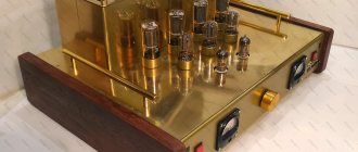
The photo shows a fashionable amplifier for tight wallets
Therefore, let’s come down to earth and try to answer questions that are relevant to most music lovers: what power is really needed for listening at home and what is the acceptable level of nonlinear distortion?
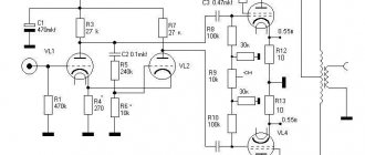
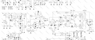
↑ My amplifier circuit using 6P3S tubes
My amp has a number of changes.
The driver operates in a higher current mode. The FI cathodes use a compound resistor, which makes it easy to adjust the bias of the lamps. The difference between the voltage at the anode of the first lamp and at the cathodes of the FI lamp should be 4-5 V. This is the bias voltage for the FI lamps. The current through these lamps is determined by the voltage drop across the load resistors of these lamps. It is no coincidence that these resistors have different values, 24k and 27 kOhm. The angle of the arms is different, so the load resistors are different - 24 kOhm and 27 kOhm. Fine-tuning the signal symmetry lies in the selection of these resistors. We will play with a 24 kOhm resistor, controlling the signal level at the anodes of the bass reflex lamps. We apply a signal to the amplifier input. We measure the voltage with a tester through a small capacitor (0.22 - 1 µF), which will cut off the constant voltage from the device. Before each (!) measurement we discharge the capacitor. Otherwise, the residual potential will spoil the readings. I soldered a 22 kOhm resistor into the anode, prepared additional resistors from 300 Ohms to 4.7 kOhms, and selected a value at which the signal level at the anodes became almost the same. The resistor can be left composite. Fragment excluded. The full version is available to patrons and full members of the community.
There is even more unusual stuff in the output stage.
The lamps operate in pentode. The second grid is stabilized not relative to the ground, but relative to the anode supply. This makes it easier to implement the use of a gas-discharge zener diode. This will appeal to orthodox lamp builders. The lamp is particularly sensitive to the drum, relative to which the grid will be stabilized. The quenching resistor is the internal resistance of the lamp.
A 100k resistor eliminates the clicking sound when the zener diode starts up. You can assemble a traditional stabilizer, on a stone zener diode, on a microcircuit, relative to mass, anode, as anyone wants. But it is advisable to stabilize the grid. The sound is then more dynamic, more accurate.
Output transformer.
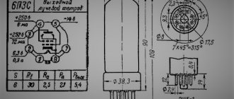
Iron OSD-03 (analogous to OSM-0.16), primary - 2500 with a tap from the middle, wound with 0.4 wire. Secondary for acoustics 8 Ohm - 96 turns. We get the reduction - 6k, active resistance 55 Ohm, inductance 30H. The transformer was wound for 6S4S. Despite its “triode” nature, it has taken root very well in this design.
Inclusion
To test the amplifier, you will need a power supply of 6 or 12 V for the filament circuits and 320 V for the anode voltage. When first turned on, it is advisable to supply high voltage from a regulated source. The control voltage values are indicated in the diagram. When a signal with an amplitude of 300 mV is applied to the input, the output should have a signal with an amplitude of about 2 V.
To check the low frequency correction you will need a +24V source. When the correction is turned on, the rise in the 60Hz should be 3 dB .
Measurement results
The measurement results are presented in the oscillograms below.
The response of the amplifier to a pulse signal shows its good stability and short rise time of the edges:
(Click to enlarge)
The cutoff frequency is approximately 140 kHz with a roll-off of -1 dB. The distortion level at a signal level of 1 V is less than 0.03%. The spectral distribution of harmonics and noise is presented in the spectrograms:
(Click to enlarge)
Note that the spectrum is dominated by the second harmonic . At the same time, its level is below -70 dB , which eliminates the “velvety” color (typical of tube amplifiers, the so-called warm sound) of the signal. The task of any amplifier is to amplify the signal without making any changes to it. This amp does it great!
The overall noise level of the amplifier before the volume control is -90 dB.
The graph shows the frequency response when the low-frequency correction circuit is turned on:
(Click to enlarge)
Please note the low impact of correction on the amplifier's frequency response and phase response. The Baxandel tone block (a fairly classic design) has a much greater influence on the output signal.
Construction details.
Resistors: R1, R2, R5, R6, R9. R10, R13, R14: selected according to the required sensitivity of the inputs (or jumpers) R3, R4, R7, R8, R11, R12, R15, R16, R17, R18: 470 kOhm / 0.5 W / 1% R19, R20: 47 kOhm /1/0.5W/1% R21, R22: 150 kOhm/2 W/ 5% R23, R24: 100 kOhm/2 W/5% R25, R26: 47 kOhm/2 W/5% R27, R28: 1 ,2kOhm/1/0.5W/1% R29, R30: 360 kOhm/0.5W/1% R31, R32: 220 kOhm/0.5W/1% R33 1kOhm/2W/5%
Capacitors
C1, C2: 1uF/50V/5mm, C3, C4: 1uF/250V/5mm, C5, C6: 0.1uF/50V/5mm C7, C8: 100uF/6.3V/3 , 5 mm, C9, C10: 470 nF / 400 V / 15 mm C11, C12: 3.3 nF / 100 V / 5 mm C13: 10 µF / 400 V / 5 mm
Miscellaneous:
Lamp: V1, V2 - 6Zh32P (EF86) Diodes: D1 -1N4007 Variable resistor: P1 - 100 kOhm (Log/ALPS) Relay: K1, K2 - SIL / Meder SIL12-1A72-71L Biscuit switch: S1 - 5P/2C / Lorlin PT6422 Toggle switch: S2 - NKK B12AH Connectors: RCA (dual) - 2 pcs., RCA (single) - 1 pc.
↑ Files
For homemade amateurs, skilled craftsmen and professionals who have the necessary fleet of machines, I provide drawings of the body design elements. Maybe it will be useful to someone.