At the request of the residents of Datagoria, I am posting the full text of Oleg Getman’s article. (AM 2002) with comments by master S. Kunilovsky.
Hi-Fi for one dollar?
What other fidelity can there be for one dollar? And you, gentlemen, audiophiles and music lovers, have you ever thought about how, in the crooked mirrors of so-called marketing policy and trade advertising, material household items and their consumer properties are distorted, and most often non-linearly?
↑ So, the whole evening at the arena “Hi-Fi for!”
Fragment excluded. The full version is available to patrons and full members of the community.
List of elements
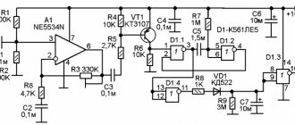
C1 (selected during adjustment) PO-750 pF ±5%-500 V C2 KT-5.6 ±0.4 pF SZ.S6 2200.0 µF-16 V (“Samsung”) C4.S5 K73-17-4 .7 µF ±10%-63 V C7 K73-17-0.22 µF ±10%-63 V
Fragment excluded. The full version is available to patrons and full members of the community.
Now I’ll tell you a little about the concept
. This device is a powerful operational amplifier in inverting connection with a gain determined mainly by the ratio R7/R5 and equal to 3. R1 channel balance; R4: volume; R1С1 high-frequency interference filter, the need for its use depends on the level of high-frequency interference and interference in the system CD player + interconnect cables + input devices (I don’t have a filter and it’s better without it, but who knows, try this and that...); C2 frequency response correction at HF to ensure device stability; R6 for connecting DC balancing circuits (Fig. 2a, b); with an output bias voltage of less than 20 mV (depending on the DAi instance, if there is somewhere to select from and the desire to do so.
Fragment excluded. The full version is available to patrons and full members of the community.
God help you, but no, no judgment) you can abandon the balancing circuits. S3S4, S5S6 filter capacitors; the closer they are located to the corresponding DA1 pins, the better. R8-R12 is exactly the same thing, the feature of the whole design is resistors that shift the operating point of the upper transistor in the circuit (L1) of the output stage Da1 to class A mode at powers up to 1 W at a load of 8 Ohms (0.5 W at 4 Ohms) (by the way , you can try using a current generator on a field-effect or bipolar transistor instead); R13-C7 provides stability against sudden changes in output voltage and load. Structurally, the very first copy was made on the basis of the Rapri UM-1 (L2) set; the second method of hanging installation using wire MGTF 0.35 and PEV2 0.8 mm; copies were also made on printed circuit boards. In any case, you should adhere to the topology presented in Fig. 1, and minimize the length of the connecting conductors.
For two channels, you can use a common radiator with an area of at least (preferably more) 800 cm2, if you are not going to create a dual mono design with separate bipolar stabilized power supplies. If you are going to do this, you should either use separate radiators for each channel, or insulate the microcircuit housings with mica spacers, since the heat sink pin is connected to pin 3 (-14 V). The power transformer for two channels must have a power of at least 120 W (try rewinding TS 180 or a suitable one from the TPP series). The diagram of the power supply option is shown in Fig. 3. VT4, VT5 are installed on separate radiators with an area of 200 cm2 each. VD9, VD12 can be selected until the supply voltage of ±14 V is obtained at the output of the power source (under a load current of 1.6 A). If you have a couple of working car batteries (at least 50 Ah), try to use them using bias adjustment diagram shown in Fig. 2b, satisfaction guaranteed.
And one more thing: using the same circuit design (Fig. 1) you can turn on the TDA1514 (a la “Linn”)
. dollar).
Main technical characteristics
Fragment excluded.
The full version is available to patrons and full members of the community. About the sound
Control path: “Sony CDP-XE 800” (or “Yamaha CDX-590”); "Monster Interlink 300 Mk II"; […]; "Monster Standard S12"; "B&W DM302" ("35AC-021"). In place of the ellipsis we substitute “Corvette”, “Marantz”, “Yamaha” in turn. “Corvette” was eliminated in the first period, “Marantz” fought for quite a long time with “Yamaha”, not that it turned out to be that good, but it was simply difficult to decide which defects in sound reproduction were more acceptable to my ears, his or “Y”. Yamaha won. Then they began to butt heads with “Yamaha” and, accordingly, what to call it (“Whatever you call the ship, that’s how they will carry it...” [4]), well, let it be “Alpha” as the first letter, so to speak. I won’t fantasize, dear readers (listeners?), and tell you that “A” immediately gored “Y” to death...
This, of course, did not happen, and in this design it could not have happened: “Y” in its category is a very good and decent-sounding product, although not without a sufficient number of purely design, to put it mildly, defects. We listened a lot, a total of more than 90 CDs. It makes no sense to describe everything I listened to for a long time, since, firstly, I do not consider myself a measure of things, a kind of compass in the world of audio expertise, and secondly, everyone’s ears and brains are different, everyone still hears something different and in my own way.
Listen for yourself, for example: WA Mozart. The Magic Flute, A Little Night Music, Piano Concerto No. 17. DDD, Point Production, 1991; Michael Bolton. My secret passion. The Arias. “Sony Music”, 1998, track 3 “Una furtiva lacrima” from Donizetti’s “Elisir of Love” - I teared up listening; Golden Collection. Johann Strauss. AAD, AT Music, 1999; Ch. Aznavour. 20 Chanson D'or. “EMI Music Holland BV”, 1997, track 13 - “La Boheme”; Astrud Gilberto. Beach Samba, 1993, track 5 “Oba, Oba”, and 9 - “My Foolish Heart”; Kate Bush Never For Ever. AAD "EMI Records Ltd.", track 10 "Army Dreamers"; Lisa Gerrard & Pieter Bourke. Duality "4AD", 1998, track 7 "Human Game"; Annie Lennox. Medusa. “BMG”, 1995, track 1 “No more “I love you's””; Mike Oldfield. Discovery. AAD, track 1 "To France"; Saint-Preux. Le piano cTAbigail. "ARCHER", 1995; Chris de Burgh. Quiet Revolution. A&M Records, 1999; Sinead O'Connor. Universal Mother, 1996.
Let's return to our sheep. “A” and “Y” butted heads, which means they are rams, they don’t stand up to bulls. “A” conveys differences in the quality of recordings better than “Y”. In terms of spatial characteristics, the scenes “A” and “Y” are approximately the same, and in terms of timbres, “A” conveys their richness noticeably better than “Y”, which sounds not so dry or poor, but somehow academically, everything seems to be in place , like “A”, but still worse. This is especially noticeable in the low-frequency region, where “A” is at the very least, but allows you to hear each bass note separately, and not in a continuous mass and in a heap, which is sometimes the case with “Y”. I told you something that is immediately and clearly noticeable. In addition, a lot of quiet sounds surfaced, which were not that there had not been there before, but that they seemed to be there, but they didn’t seem to be there.
Now I’ll say what I consider the main property of this design, listening to music in the path with “Y” is noticeably more boring than with “A” (Well, yes, yes, not as interesting as, for example, with a hybrid SE on 6N23P + BUZ10 without OOS, as they say, “A” was not even close to it, and not as much as with the “budget” bipolar-field SE (two cascades with shallow OS), and certainly not as with SE on 6S4S + 6N23P ), but still…
And one more thing: you can listen to music with “A” at such low volumes that most transistor amplifiers do not yet come to life. And you won’t disturb your neighbors, your ears will be healthier, and the acoustic response of the listening room will be less. In conclusion of my opus, I would like to once again remind you of the goal of developing this design, burdened by the inevitable evil of shortcomings (take, for example, the presence of deep OOS...), to make the first step towards High Fidelity as easy and cheap as possible for a person who is interested in music not only as a background, but also itself, as some other world created by generations of composers and listeners, and provide it with a tool for this step that is quite universal in terms of genre preferences and easy to repeat (you will agree that the circuitry of “Alpha” is simpler than, say, Makarovsky’s “MAG 3.5” ").
Oleg Getman Audio store, 2002
For unipolar power supply
A typical circuit with a unipolar power supply (PS) differs from the previous one in the presence of a bias circuit necessary to provide half the supply voltage at the output (Output 4) of the microcircuit. This circuit consists of a divider (R1, R2) and resistance R3. It is required to ensure equal gain for both negative and positive half-waves.
The gain is set by the ratio of the values of R4 and R5. The technical characteristics of this amplifier with a supply voltage of +36 V are equivalent to the previous circuit with bipolar power supply from +18 to -18 V.
↑ My amplifier
My board layout is somewhat irregular and is determined by the type of bias resistors used. It is better to place them on both sides of the board and follow the rule of the shortest conductors. It all heats up well. I used active body blowing. In the breadboard I tried to insert a current generator on an LT1083 with a good heatsink. The sound is improving. The design becomes more compact.Beginner Kits
Currently, on the Internet and on the shelves of radio stores, you can find not only ready-made modules using the solutions discussed, but also kits for beginner radio amateurs. An example of assembling an audio amplifier using such a constructor is shown in the video.
At the same time, many radio amateurs are more interested in finding and soldering everything themselves. To do this, you can download one of the datasheets for TDA2030 (STMicroelectronics), which also presents examples of its application, by following the link.
↑ Estimation of radiator cooling surface area
The microcircuit must be installed on a radiator - after all, even at rest, it dissipates power equal to P0=UpI0=(2•25)•0.07=3.5 W.
To calculate the required radiator area, we calculate the maximum power dissipation for the case of operation in ideal class B: where Up is the total voltage of the power source, Rн is the load resistance, P0 is the power dissipated in idle mode. At full power supply voltage Uп =50 V, Rн =8 Ohm, the power of about 19.3 W should be dissipated on the microcircuit body. It is clear that the temperature of the crystal during operation should always be below 150ºС. Let's take the ambient air temperature to be 53 ºС, then the thermal resistance of the transition - environment should be less than: (150-53)/19.3=5.0 ºС/W. Typically, the sum of the thermal resistances of the case - radiator and radiator - environment is less than 2.0 ºC / W. The thermal resistance of the case - heatsink depends on the method of installing the microcircuit. If a direct metal-to-metal connection is used, the thermal resistance will be approximately 1.0 ºC/W when using thermal conductive paste and 1.2 ºC/W when not.
If there is a mica gasket between the case and the radiator, the thermal resistance can be considered equal to 1.6 ºC/W and 3.4 ºC/W, respectively, when using thermal conductive paste and without it. As an example, consider attaching a microcircuit to a radiator through a mica gasket using heat-conducting paste. The thermal resistance of the radiator must be less than 5.0 – 2.0 – 1.6 = 1.4 ºС/W. This is the recommended heat sink thermal resistance for this design.
It is useful to evaluate the results of radiator calculations using some program, for example, [4]. The most approximate calculation of the area of the cooling surface of the radiator: 20 square centimeters for each watt of power dissipated by the microcircuit. For radiators made of aluminum alloys with fins no thinner than 3 mm, with a fin pitch of at least 10 mm and free air flow, the radiator area can be estimated by the following approximate formula: S[sq cm]≈600/Rθр-с[ºС/W]=600 /1.4=430 sq cm. As already mentioned, the LM1875
equipped with an effective thermal protection circuit. When the temperature of the microcircuit crystal reaches 170 ºС, the thermal protection circuit is triggered and the amplifier turns off. Switching on occurs after the crystal temperature drops to 145 ºС. However, if the temperature of the crystal begins to rise again, then the shutdown will now occur at 150 ºС.
↑ “Student” UMZCH Peter Smith
LM1875
chip allows us to hope that there are complete designs based on it.
And so it turned out - let's assemble a magnificent amplifier by Peter Smith
, published in the April 2007 issue of the English magazine “Everyday Practical Electronics” [8]. The author called it "student". Indeed, it is easier to assemble than the design of 35 years ago [1]. The schematic diagram of one amplifier channel is shown in Fig. 4, and the power supply for it is shown in Fig. 5. The power supply is equipped with an optional option - a compensating bipolar stabilizer, which can be useful for powering a pre-amplifier or tone control unit.
Fragment excluded. The full version is available to patrons and full members of the community.
Rice.
4. Schematic diagram of Peter Smith’s “student” amplifier The power amplifier has the following parameters:
Nominal output power (Rн = 4 Ohm; 8 Ohm), W = 20 Operating frequency range with an output power of 1 W, Hz = 14...100000 Harmonic distortion at frequency 1 kHz at 20 W output power, dB = -105
Fragment excluded. The full version is available to patrons and full members of the community.
Rice. 5. Schematic diagram of the power supply for the Peter Smith amplifier
Although the microcircuits listed in table. 1 are simple and easy to use, they require careful consideration of wiring when designing a printed circuit board to ensure stable and reliable operation. The printed circuit board designed by Peter Smith is an example of competent wiring of high- and low-current amplifier circuits, and can be safely recommended for repetition (Fig. 6), as well as the power supply (Fig. 7).
Fragment excluded. The full version is available to patrons and full members of the community.
Rice. 6. Placement of elements and printed circuit board of a “student” power amplifier. PCB dimensions – 80x63.5 mm
Fragment excluded. The full version is available to patrons and full members of the community.
Rice. 7. Placement of elements and printed circuit board (90x54.5 mm) of the power supply for the Peter Smith amplifier
Here a question has arisen that requires clarification.
Housing and power supply
Take a power supply either with a transformer plus a rectifier, or a ready-made switching one, for example from a laptop. The amplifier must be powered with an unstabilized voltage within the range of 12 – 30 V. The maximum supply voltage is 35 V, which is naturally better not to reach by a couple of volts, you never know.
Making a case from scratch is very troublesome, so the easiest way is to choose a ready-made box (metal, plastic) or even a ready-made case from an electronic device (satellite TV tuner, DVD player).
Schematic diagram of the ULF
Amplifier 2x15W TDA2030 – stereo circuit
TDA2030A allows you to solder a low-frequency amplifier of class AB. The microcircuit provides a large output current, while being characterized by low signal distortion. There is built-in short circuit protection, which automatically limits the power to a safe value, as well as thermal protection traditional for such devices. The circuit consists of two identical channels, the operation of one of which is described below.