LOW FREQUENCY POWER AMPLIFIERS ON ICIRCUITS
Amplifiers whose main purpose is to amplify the signal by power are called power amplifiers. As a rule, such amplifiers drive a low-impedance load, such as a loudspeaker.
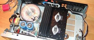
Large currents flow through the output transistors of such microcircuits; the microcircuits heat up noticeably during prolonged operation. Therefore, to ensure normal operating conditions, power amplifier microcircuits must be installed on heat sinks. Modern power amplifier microcircuits have protection against overheating and load short circuit.
An example of a practical ULF circuit that implements the use of an external output transistor stage is shown in Fig. 31.1
[31.1.31.2] .
Low-frequency amplifier intended for use in a connected receiver (Fig. 31.1) with an output stage using transistors KT814A and KT815A
[31.2] at a load of 8 Ohms develops a power of 110-120 mW, consuming a current of only 0.6 mA in idle mode. Amplifier sensitivity - 10 mV. The capacitor SZ was chosen for reasons of ensuring the cutoff frequency of the frequency response at a frequency of 3.0-3.4 kHz. The gain of the output stage is determined by
Rice. 31.1. ULF on the K140UD1208 chip
divided by the ratio of resistors R8/R10. The value of resistor R6 is selected based on the minimum quiescent current consumption and an acceptable level of distortion.
Rice. 31.2. Stereo preamplifier circuit based on LM387AN chip
When using transistors KT502 and KT503 (or KT3107 and KT3102) and a load resistance of 50 Ohms, the quiescent current is 0.5-0.6 mA, the output power of the amplifier is lower [31.1].
Rice. 31.3. Stereo preamplifier circuit based on pA749D chip
The LM387AN chip is intended for use as a preamplifier for stereo radio equipment. The nominal supply voltage of the microcircuit is 12 V with a current consumption of 10 mA, the maximum is 30 V. The amplified frequency band is from 20 Hz to 1.8 MHz with a harmonic coefficient of no more than 0.1%. Gain: up to 104 dB. Input impedance - 100 kOhm. A variation of the LM387AN microcircuit is also available in a round TO-99 package (with the same pinout numbers). The transmission coefficient of the preamplifier (Fig. 31.2) is determined by the ratio of resistive elements R1-R3 and R4-R6 for each channel.
A degraded analogue of the LM387AN microcircuit is the μΑ749Ό microcircuit (Fig. 31.3). The rated supply voltage of this microcircuit is 12 V with a current consumption of 3 mA, the maximum is 24 V. The amplified frequency band is from 20 Hz to 20 kHz with a harmonic coefficient of no more than 0.1%. Gain: up to 86 dB. Input impedance - 150 kOhm. It should be taken into account that the microcircuit marked μΑ749ΌΗΟ is also available in a round TO-99 package (with the same pinout numbers), and under the mark μΑ749Ω8 - in a DIP14 package.
A linear preamplifier based on the ΑΝ127 chip, operating in the frequency band 20 Hz–1.8 MHz with a supply voltage of 1.3–5 V and a current consumption of 1.2 mA, is shown in Fig. 31.4. The amplifier's input impedance is 3 kOhm, output impedance is 500 Ohm, output voltage is 0.1 V, gain is 57 dB. The disadvantage of the amplifier is the increased nonlinear distortion coefficient - up to 1.8%.
A ULF with an output power of up to 1 W, designed to operate with a load of 8 Ohms at a supply voltage of 12 V and a quiescent current of 7.5 mA, can be made on U410B and U821B microcircuits. The first of them is capable of operating at supply voltages from 3 to 15 V, the second - from 2 to 16 V in the frequency ranges with typical switching on 40-18000 and 50-20000 Hz, respectively, Fig. 31.5 and fig. 31.6.
Rice. 31.4. Linear preamplifier circuit based on AN 127 chip
Rice. 31.5. ULF circuit on the U410B chip
ULF on the TVA820M microcircuit (analogues of JJ820, LM820M, KA2201) Typical switching circuits of which are shown in Fig. 31.7 and fig. 31.8, provide output power up to 1.8-2.0 W at a supply voltage of 12 V. Amplified frequency band - 30 (40) -
18000 Hz. Recommended load resistance is 4 ohms. The ULF supply voltage can be 3-16 V.
Rice. 31.6. ULF circuit on the U821B chip
The input impedance of the microcircuit is 5 MOhm. Gain up to 56 dB.
A fairly simple preamplifier for the low-frequency range 20 Hz–20 kHz can be assembled on the TVA880 microcircuit, Fig. 31.9. The microcircuit has 2 power pins, input and output. Rated supply voltage 4.6 V (maximum - 12 V) with a current consumption of 18 mA. The amplifier input impedance is 12 kOhm, output impedance is 200 Ohm. Gain - 46 dB, nonlinear distortion - up to 5%. An almost complete analogue of this microcircuit is the TCA980 microcircuit, differing only in its increased output voltage.
The TA7368P chip from Toshiba is designed to create simple ULFs, Fig. 31.10, fig. 31.11. The supply voltage of the microcircuit can vary within 2-10(14) V (nominal 4 V). The output power when operating at a load resistance of 4 Ohms reaches 1.1 W in the frequency band 20-20000 Hz with a harmonic distortion coefficient of up to 0.2%.
Gain: 40 dB. The input impedance of the microcircuit is 27 kOhm.
Rice. 31.7. ULF circuit on the TVA820M (U820) chip
ULF on the KR1064UN2 microcircuit (analogues of EKR1436UN1, MS34119R,
Rice. 31.8. Variant of the ULF circuit on the TVA820M (U820) chip
Motorola) operates at a supply voltage of 2-16 V (Fig. 31.12, 31.13). The quiescent current is 4 mA. When the SA1 “Mute” key is turned on, the current consumed by the microcircuit is reduced to the leakage current (about 65 μA). The output power of the amplifier in the frequency range 50-16000 Hz per load resistance of 8 Ohms at a supply voltage of 9 V reaches 250 mW with a harmonic distortion of 0.22%. Gain: 46 dB.
An option for switching on the MC34119R microcircuit is shown in Fig. 31.14. The ULF gain is defined as 2R2/R1. The remaining characteristics are the same as those of analogues, see above, but the quiescent current is only 2.7 mA. Relatively high-impedance phones can be used as a load - 32 Ohms.
Rice. 37.9. Amplifier circuit based on TVA880 chip
Rice. 31.10. Equivalent circuit of the TA7368R chip
Rice. 31.12. Equivalent circuit of microcircuits KR1064UN2 (EKR1436UN1, MS34119R)
Rice. 31.11. ULF circuit on the TA7368R chip
Rice. 31.13. ULF circuit on the KR1064UN2 microcircuit
Rice. 31.14. ULF circuit on the MC34119R chip
Rice. 31.15. Composition and pinout of microcircuits of the LM358, K1464UD1 series
Microcircuits of the LM358 series (National Semiconductor Corporation, NSC), the domestic analogue is K1464UD1, consist of two operational amplifiers (Fig. 31.15) in a DIP8 package (or T099, S08). The supply voltage of the microcircuit is ±3 - ±32 V, the gain is up to 100 dB [31.3].
Based on the K1464UD1 op-amp, a stable current generator can be manufactured with several outputs, the diagram of which is shown in Fig. 31.16 [31.3]. Resistors Rl, R2 form a voltage divider. The reference voltage from this divider (iobr = 3 V) is supplied to the input of the op-amp. The current through transistor VT1 creates a voltage drop across resistor R3. This voltage serves as a negative feedback signal to the op-amp, which stabilizes the current through the transistor. Then
At high current transfer coefficients of transistors, you can take 1e1=1e2; IKl=IK2. With the KT315E transistor, the source can provide an output current of up to 50 mA.
When designing tape recorders, the problem of ensuring
Rice. 31.16. Multi-stable current generator circuit
Rice. 31.17. Diagram of the recording output stage of a tape recorder (recording voltage-current converter)
recording and playback of high frequencies. The circuit design shown in Fig. 31.17, allows you to stabilize the write current regardless of the frequency of the input signal [31.4]. For this purpose, an amplifier is used, which acts as a voltage-to-current converter.
The current sensor R6 maintains a constant voltage difference throughout the entire audio frequency range. The magnitude of this current can be adjusted by selecting the value of this resistor. The maximum voltage on the recording head B1 is limited by the supply voltage swing, therefore, in order to achieve the upper recording limit of 22 kHz, it is advisable to apply a voltage increased to ±30 V or more to the transducer of the mountain of the output stage.
The LA4140 microcircuit (Sanyo) is intended for use in the output stages of monophonic tape recorders, CD players, and radio receivers. A typical ULF circuit using this microcircuit is shown in Fig. 31.18. The microcircuit can operate with a supply voltage of 3.5-14 V to a load resistance of 16 Ohms, with
Rice. 31.18. ULF circuit on the LA4140 chip
a load resistance of 8 Ohms, the upper limit of the supply voltage is reduced to 12 V. The current consumed by the amplifier at a supply voltage of 6 V does not exceed 11 mA. The output power at a load resistance of 8 Ohms reaches 500 mW with a CNL of no more than 10%. Gain: 50 dB. Input impedance - 15 kOhm, output noise level - 400 µV.
The ULF on the LA4145 chip has a higher output power, Fig. 31.19. The amplifier supply voltage on this chip is 3.6-8.0 V.
Rice. 31.19. ULF circuit on the LA4145 chip
Rice. 31.20. Equivalent circuit of TDA10WA, TDA1011, TDA1015, TDA1020 microcircuits.
PU—preamplifier; PA - power amplifier
Current consumption at a supply voltage of 6 V is 10 mA. Output power at CNL up to 10% and load resistance 8 Ohms - 600 mW; at 4 Ohms - 900 mW. Gain: 50 dB. Input resistance - 30 kOhm, output noise level - 600 µV.
The TDA1010A microcircuit (Philips) is designed to operate at increased supply voltage (6-24 V), rated voltage 14.4 V. The equivalent circuit of microcircuits in this series is shown in Fig. 31.20, and typical diagrams of practical use are shown in Fig. 31.21 and fig. 31.22. The ULF output power on the TDA1010A chip with a load resistance of 2 Ohms can reach 9 W with a harmonic distortion of 0.2%. The gain can reach up to 54 dB. Input impedance - 20 kOhm.
Rice. 31.21. ULF circuit on the TDA 1010A chip
ULF on the TDA1020 chip (Fig. 31.22), provides an output power of 12 W into a resistance of 2 Ohms; harmonic distortion 0.2%, voltage
Rice. 31.23. Typical circuit diagram for switching on a TDA 1011, TDA1015 microcircuit
Rice. 31.22. Variant of ULF circuit on TDA1010A, TDA1020 microcircuits
amplifier) + 29 (power amplifier) = 52 dB. Input impedance over 100 kOhm. A type of microcircuit in the S08 package - TDA1015T has a different pinout and “lightweight” characteristics (output power up to 0.5 W with a supply voltage of 9 V and a load resistance of 16 Ohms).
Power supply 14.4 V (car battery), supply voltage change limits 6-18 V. Gain 47.3 dB - 17.7 (preamplifier) +
29.5 (power amplifier). Input impedance - 40 kOhm.
The TDA1011 microcircuit (Fig. 31.23) is designed to operate at a rated supply voltage of 16 V (limits 3.6-24 V). The ULF output power when operating at a load resistance of 4 ohms is
6.5 W at 0.2% harmonic distortion. Gain: 52 dB. Input impedance - 200 kOhm.
The TDA1015 chip (Fig. 31.23) operates at a nominal supply voltage of 12 V (limits 3.6-18 V). The ULF output power with a load resistance of 4 Ohms is 4.2 W with a harmonic distortion of 0.3%. When the supply voltage decreases to 9 (6) V, the output power drops to 2.3 (1.0) W.
Gain frequency range at -3 dB—60—15000 Hz. Gain - 23 (pre-
The TDA1013B microcircuit differs from its predecessors in pinout (Fig. 31.24) and, accordingly, in the connection circuit (Fig. 31.25).
With a supply voltage of 18 V, the output power into a resistance of 8 Ohms is 4.2 W at Fig. 31.24. Equivalent to harmonic distortion 0.2%. Coefficient circuit of the TDA101ZV microcircuit
gain - 38 dB. Input impedance - 200 kOhm.
Rice. 31.25. Typical connection circuit for the TDA101ZV microcircuit
The TDA1518Q chip (Philips) is capable of delivering up to 11 W or more power to the load at 10% CNL (depending on the quality of the radiator). Microcircuit supply voltage 6-18 V, optimal
Rice. 31.26. ULF circuit on TDA 1518Q chip
Rice. 31.27. Stereo ULF on TDA 1518Q chip
14.4 V. Recommended load resistance 2 ohms. The microcircuit allows operation in both mono and stereo (two-channel) modes, Fig. 31.26 and fig. 31.27. Gain in the frequency band 20-20000 Hz - 40 dB. Key S1 is designed to disable the microcircuit (Stand-By mode). An analogue of the TDA1518Q chip is the TDA1516Q with a gain reduced to 20 dB and a CNL of 0.2%.
When introducing positive feedback into the ULF on the TDA1518BQ chip, Fig. 31.28, goes into generation mode, producing a signal with a frequency of about 2 kHz [31.5].
Rice. 31.28. High-power sound generator circuit based on TDA1518BQ chip
The TDA1553Q chip contains two bridge amplifiers, the circuit of which is shown in Fig. 31.29, to the outputs of which low-resistance loads (2×4 Ohms) can be connected without transition capacitors. With a supply voltage of 12-14.4 V, for example, from a car battery, the output power for each channel can reach up to 22 W with a CNL of no more than 0.2-0.5%. Gain: 26 dB. The S ι key is designed to switch the microcircuit to the “Stand-By” mode (sleep mode).
Rice. 31.29. ULF on TDA1553Q chip
Based on the TDA1553Q chip or its analog TDA1557Q, a car power amplifier for an audio player can be assembled (Fig. 31.30) [31.6]. To power the audio player, a voltage of about 2.8 V (two AA batteries) is usually used. This voltage can be easily obtained using a voltage stabilizer powered from a car battery.
Note.
Originality of the circuit design, Fig. 31.30, is that the voltage stabilizer simultaneously controls the “Stand-By” mode of the power amplifier.
To switch the amplifier to this mode, simply turn off the power to the audio player. Then the current through the current sensor resistor R3 is interrupted, the transistor VT3 is turned off, and pin 11 of the DA1 chip is connected to the common bus. The amplifier turns off. To reduce the level of noise in the power supply circuit of the amplifier, a noise suppression choke should be installed.
The TDA2822 chip (Philips) is designed for assembling simple mono or stereo ULFs (Fig. 31.31 and 31.32), operating in the frequency range 30 Hz - 18 kHz with an output power per channel of up to 1.8 W at a supply voltage of 6 V. Allowable range supply voltages - 3-15 V.
Rice. 31.30. Stereo power amplifier circuit for audio player based on TDA1553 chip
Note.
The TDA2822M chip has a similar circuit, but it is made in a different package and has a different pinout and characteristics (output power reduced to 0.65 W).
The ULF on the TDA2006 chip, connected almost according to a standard circuit (Fig. 31.33), operates from a power source with a voltage of 4.5-13.5 V
[31.7]. Its gain can be smoothly adjusted using potentiometer R4. The input impedance of the amplifier is about 100 kOhm.
Rice. 31.31. Typical stereo ULF circuit on the TDA2822 chip
Rice. 31.32. Typical circuit of a single-channel ULF on a TDA2822 chip
Rice. 31.33. ULF circuit on TDA2006 chip
Typical circuit diagrams for connecting the 1TDA7050 microcircuit (Philips) in two- and single-channel ULFs are shown in Fig. 33.34 and fig. 33.35 [31.8]. The supply voltage of the microcircuit can be 1.6-6.0 V. The quiescent current at a supply voltage of 3.0 V is 3.2 mA. Voltage gain 32 dB (bridge mode) 26 dB (stereo mode). Limit operating frequency up to 500 kHz. The output power in bridge mode at a supply voltage of 3.0–4.5 V and a nonlinear distortion coefficient of up to 10% is about 140–150 mW. In stereo mode - 35 and 75 mW at a supply voltage of 3.0 and 4.5 V. Input impedance - 1 MOhm. Load resistance in bridge mode - 8-64 Ohms, fig. 31.34, in stereo mode - 32 Ohms, fig. 31.35.
In a mono-channel connection, the load (electrodynamic loudspeaker) is connected via a bridge circuit, so there is no need to use transition capacitors that limit the frequency range.
The monophonic bridge ULF on the TDA7052 chip (Fig. 31.36, Fig. 31.37) can operate in the supply voltage range
Rice. 3 Ί.34. Two-channel ULF on the TDA7050 chip
Rice. 31.35. Monophonic ULF circuit on the TDA7050 chip
voltage 3-18 V (nominal - 6 V) [31.8]. The maximum current consumption is 1.5 A with a quiescent current of 7 mA (at 6 V) and 12 mA (at 18 V). Voltage gain 36.5 dB. Amplifier bandwidth at -1 dB 20 Hz - 300 kHz. Rated output power at 10% THD
1.1 W. Input impedance 100 kOhm. Load resistance 8 ohms.
The bridged stereophonic ULF (Fig. 31.38) on the TDA7053 chip is also capable of operating in the supply voltage range of 3-18 V (nominal 6 V at a quiescent current of 9 mA). Output power per channel at a supply voltage of 6 V and a load resistance of 8 Ohms is 1.2 W (non-linear distortion coefficient 10%). Frequency band 20-20000 Hz. Maximum current consumption up to 1.5 A. Input impedance 100 kOhm. Load resistance 8-32 Ohm.
Rice. 37.36. ULF circuit on the TDA7052 chip
Rice. 31.37. A variant of the ULF circuit on the TDA7052A chip with a volume control
Rice. 31.38. Stereo ULF circuit on TDA7053 chip
The ULF on the TDA7231 chip (Fig. 31.39) can operate at a supply voltage of 1.8-15 V. With a supply voltage of 12 V, the output power into a 4 Ohm load reaches 1.6 W in the frequency range 40-18000 Hz. The quiescent current of the microcircuit is about 4 mA.
Rice. 31.40. Pinout of TDA7233, TDA7233D chips
Rice. 31.39. ULF circuit on TDA7231 chip
Microcircuits TDA7233, TDA7233D (ST Microelectronics) with an output power of up to 1 W are intended for portable, economical household sound-reproducing devices, Fig. 31.40 and fig. 31.41 [31.9, 31.10].
Note.
The pinout of microcircuits made in Minidip and S08 packages differs from each other, namely, for the TDA7233 microcircuit, the Zi4 pins (power!), in contrast to the TDA7233D, are swapped, Fig. 31.40.
The operating voltage range of the microcircuits is 1.8-15 V. With a supply voltage of 6 V, the gain is 39 dB. Frequency range 22 Hz—22 kHz. Input impedance 100 kOhm. Load resistance 4(8) Ohm. The microcircuits have a pin - 2 “Mute” (“Disabled”), which allows you to save battery life when you close this pin to the common wire (switch SA1).
Rice. 31.41. Typical monophonic ULF circuit on the TDA7233D chip
Rice. 31.42. ULF double output power on TDA7233D chips
temporarily turn off the sound. You can double the ULF output power on TDA7233D microcircuits when you turn them on according to the circuit shown in Fig. 31.42 [31.10]. Capacitor C7 prevents self-excitation of the device in the area
high frequencies. Resistor R3 is selected until an equal amplitude of the output signals is obtained at the outputs of the microcircuits.
Rice. 31.43. Block diagram of the KR174UNZ 7 microcircuit
The KR174UN31 microcircuit is intended for use as low-power ULF output for household electronic devices.
When the supply voltage changes from
2.1 to 6.6 V with an average current consumption of 7 mA (without input signal), the voltage gain of the microcircuit varies from 18 to 24 dB [31.11].
The coefficient of nonlinear distortion at an output power of up to 100 mW is no more than 0.015%, the output noise voltage does not exceed 100 μV. The input impedance of the microcircuit is 35-50 kOhm. Load resistance is not lower than 8 ohms. Operating frequency range - 20 Hz - 30 kHz, maximum - 10 Hz - 100 kHz. The maximum input signal voltage is up to 0.25-0.5 V.
The block diagram of the KR174UN31 microcircuit is shown in Fig. 31.43. Pin 6 is a blocking filter, pin 7 is an offset divider filter.
The output power of the stereo ULF (Fig. 31.44) on the KR174UN31 microcircuit per channel at a supply voltage of 6.0 V is 0.44 W, at 4.5 V - 0.24 W, at 3.0 V - 0.1 W.
Output power of monophonic ULF (Fig. 31.45) on the KR174UN31 microcircuit for each channel at a supply voltage of 6.0 V -
1.1 W, at 4.5 V - 0.54 W, at 3.0 V - 0.2 W.
Rice. 31.44. Stereo ULF circuit diagram on the KR 7 74UNZ chip C1=C4=C8=0.15 µF, C2- 7 00 µF, SZ=10 µF, C7= 7 000 µF, C5-C6-500 µF
Rice. 31.45. Monophonic ULF circuit on the KR 7 74UNZ microcircuit 7 С1=С4-С6=0.75 µF, С2=2000 nF, СЗ=УмкФ, С5-У00мкФ
The KR174UN34 microcircuit produced by Angstrem OJSC (Fig. 31.46) is a two-channel low-frequency power amplifier with an output power of up to 1.3 W at a supply voltage of 6 V [31.12]. Supply voltage 2-9 V (maximum - 1.8-15 V). Current consumption in mode
silence at a supply voltage of 6 V - less than 9 mA. The gain at a supply voltage of 6 V and a load resistance of 4 Ohms is 36-41 dB. Input impedance - at least 100 kOhm.
Rice. 31.48. Diagram of a bridged monophonic ULF on the KR174UN34 microcircuit
Stereo ULF (Fig. 31.47) on the KR174UN34 microcircuit at a supply voltage of 2 V (load resistance 32 Ohms) provides an output power of 2 mW per channel at a 10% CNL; at 3 V (4 Ohms) - 40 mW, at 6 V (8 Ohms) - 300 mW; at 6 V (4 Ohms) - 450 mW; at 9 V (8 Ohms) - 600 mW.
Rice. 31.49. Appearance and pinout of the TDA2030 microcircuit (K 7 74UN79)
Rice. 31.46. Structural Fig. 31.47. Stereo circuit
circuit diagram of the KR174UN34 ULF microcircuit on the KR174UN34 microcircuit
A monophonic ULF using a bridge circuit (Fig. 31.48) with a supply voltage of 2 V (load resistance 4 Ohms) provides an output power of over 30 mW at a CNL of 10%; at 3 V (8 Ohms) - 120 mW; at 3 V (4 Ohms) - 200 mW; at 4.5 V (4 Ohms) - 400 mW; at 6 V (8 Ohms) - 900 mW; at 9 V (16 Ohms) - 1400 mW.
The TDA2030 microcircuit, manufactured by RFT, SGS-Thomson Microelectronics, ST Microelectronics [31.8, 31.13], is intended for creating inexpensive ULFs with an output power of up to 10-12 W (depending on the supply voltage and the heatsink used), Fig. 31.49 and fig. 31.50.
The domestic analogue of the microcircuit is K174UN19. The microcircuit provides protection against load short circuit and overheating.
Rice. 31.50. Typical scheme for using the TDA2030 (K174UN19) microcircuit as a ULF
Typical characteristics of ULF (Fig. 31.50) on the TDA2030 chip: maximum supply voltage up to 18 V, output power up to 20 W. When powered from 14 V, the output power is reduced to 14 W at a load resistance of 4 ohms with a CNL of 0.5%. The amplified frequency band, depending on the type of microcircuit, is 30 Hz - 20 kHz (40 Hz - 15 kHz).
In parallel with resistor R6, in order to correct the amplitude-frequency characteristics of the ULF, you can connect a series RC circuit of 10 pF, 15 kOhm with the selection of element values, Fig. 31.50.
When using a bipolar power supply, the circuit diagram of the microcircuit is modified, Fig. 31.51. The C4R4 correction chain may be missing.
Rrs. 31.51. Typical circuit diagram for connecting the TDA2030 (K174UN19) microcircuit as a ULF powered from a bipolar power supply
Rice. 31.52. 28 W bridge amplifier circuit. on TDA2030 chips (K 174UN19) powered by a bipolar power supply
The bridge ULF on TDA2030 (K174UN19) chips with an output power of up to 28 W is powered by a bipolar power supply with a voltage of ±14 V, it is shown in Fig. 31.52 [31.13]. Corrective RC circuits can be connected in parallel with resistors R3 and R7, see, for example, Fig. 31.51.
In Fig. 31.53 shows the use of the TDA2030 microcircuit
when used as part of active speakers for a personal computer (one of the channels is shown) [31.14].
The ULF amplification factor (20 times) is determined by the ratio R5/R6. Capacitors C2, C6 and C5 determine the lower limit of the amplified frequencies. The R7C7 chain increases the stability of the ULF in the high frequency region.
The ULF (Fig. 31.54) on the TDA2030A chip with an output power of up to 30 W [31.8] operates in the frequency range 40 Hz - 15 kHz, providing a CNL of 0.5%.
Rice. 31.53. ULF on TDA2030 chip
Rice. 31.55. Powerful sound generator circuit
On the TDA2030 chip, designed to work as the output stage of a powerful ULF, an equally powerful audio signal generator can be assembled, the circuit of which is shown in Fig. 31.55 [31.15].
Such a generator can be used for a burglar alarm, as a vehicle horn, an electric bell, a device for repelling animals and insects, etc.
The frequency of the sound signal can be varied smoothly by adjusting potentiometer R5, and roughly by switching the capacitance of capacitor C1. The microcircuit must be installed on heat-dissipating plastic. At a supply voltage of 20 V, the device consumes a current of 400 mA, at 4 V - 25 mA.
Rice. 31.54. High power ULF circuit using TDA2030A chip
If you could replace the BA1 head with a simple rectifier, then using a generator you can get a fairly powerful voltage converter of any polarity.
A simple ULF (Fig. 31.56) on the K157UD1 microcircuit can be used as the output stage of a transceiver, communication line, intercom, or intercom [31.16].
Shustov M. A., Circuitry. 500 devices on analog chips. - St. Petersburg: Science and Technology, 2013. -352 p.
Tweet Like
- Previous post: COLLECTIVE TV ANTENNA
- Next entry: TROUBLESHOOTING IN ELECTRONIC TELEPHONES - DO IT YOURSELF
- Preventing Excessive Power Dissipation in Linear Regulators (0)
- Power regulators for a soldering iron, another diagram (0)
- About frequencies, periods, power, alternating voltages and currents and a little about signals (0)
- Power - basic concepts (0)
- AUDIO PREAMPLIFIER WITH AGC (2)
- MOTORCYCLE SECURITY ALARM (0)
- POWER SUPPLY FOR CAR RADIO (0)
Related posts:
Basic principles of operation of a class D UMZCH with a bridge output without a low-pass filter
A simplified diagram of this UMZCH is shown in Fig. 3. It also contains two output amplifiers (channels), the LF signals at the outputs of which have the same range but opposite phases.
Simplified circuit of a class D UMZCH with a bridge output without a low-pass filter (Fig. 3)
Rice. 3. Simplified circuit of class D UMZCH with bridge output without low-pass filter
Each channel has its own PWM. Moreover, the rectangular signals in quiescent mode at the output of the circuit are not at all antiphase, as in the previous circuit, but are in phase or have a slight phase shift (see Fig. 4).
Diagrams of voltage and output current of a class D UMZCH with a bridge output without a filter in rest mode (top) and with a positive instantaneous value of the low-frequency signal (bottom) (Fig. 4)
Rice. 4. Diagrams of voltage and output current of a class D UMZCH with a bridge output without a filter in rest mode (top) and with a positive instantaneous value of the low-frequency signal (bottom)
This is achieved using an inverter (Fig. 3) with a voltage gain of 1 (KU = 1). As a result, in the worst case, the loudspeaker in rest mode receives antiphase symmetrical pulses of short duration (Fig. 4). To smooth them out, a small capacitance and inductance of the loudspeaker are used. Comparing Fig. 4 and fig. 2, it is easy to notice that the load current in quiescent mode is noticeably lower in the circuit of Fig. 3 than in the diagram in Fig. 1. In the mode of amplifying the input low-frequency audio signal, the PWMs operate in antiphase, that is, if the duration of the pulses at the output of one PWM increases, then at the output of the other it decreases, and vice versa (Fig. 4). This leads to an asymmetry of the pulses applied to the load, and therefore to the appearance of a component in the loudspeaker current, the magnitude of which depends on the difference in the duration of the PWM 1 and PWM2 pulses. This component changes according to the law of the input low-frequency sound signal and will be converted by the loudspeaker into acoustic vibrations.
Review of Class D UMZCH microcircuits from Texas Instruments
Texas Instruments Corporation produces many microcircuits for class D UMZCH. You can still find first-generation microcircuits in products and on sale, such as TL1451, TL1453 and others, which were developed back in the early 80s. But the later class D UMZCH microcircuits are much more interesting. One of the latest releases features 19 such microcircuits. Their main parameters and characteristics are given in Table 1.
Table 1. Parameters of UMZCH class D microcircuits from Texas Instruments
Let's take a closer look at two Class D UMZCH microcircuits from this table, one of which is a mono amplifier, and the other is a stereo amplifier.